
Pemasa 555: tekan butang, menyala 5 saat
Tekan butang sekali dan LED menyala selama kira-kira 5 saat, kemudian padam dengan sendirinya. Litar ini ialah mod monostabil NE555, iaitu mod satu pukulannya: asas bagi pemasa lampu tangga, lampu bertangguh dan pemasa. Masa ditetapkan hanya oleh satu perintang dan satu kapasitor. Kamu mencuba input picu, voltan ambang dan formula T = 1.1 × R × C dalam litar yang kamu bina sendiri.
Video
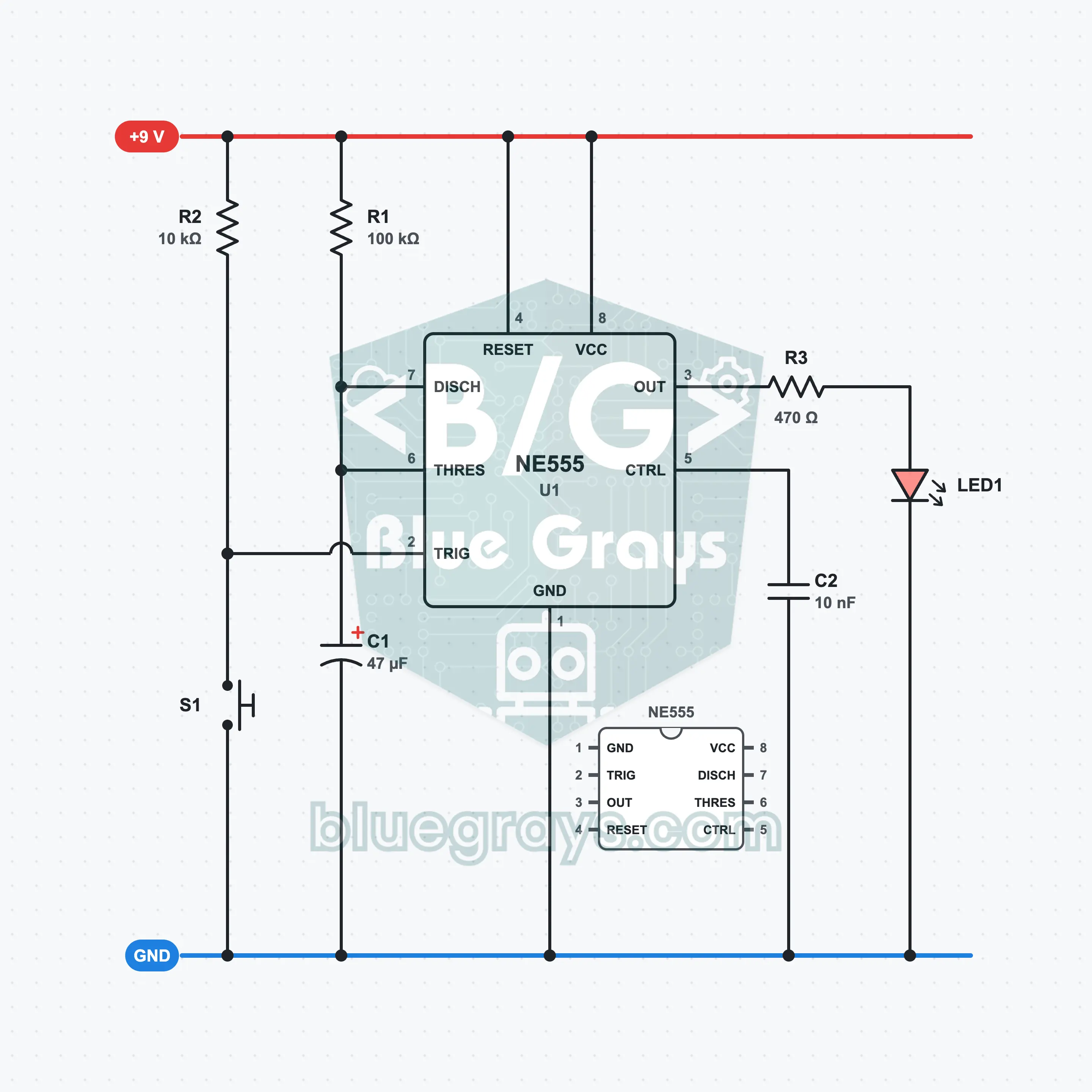
Gambar Rajah Litar
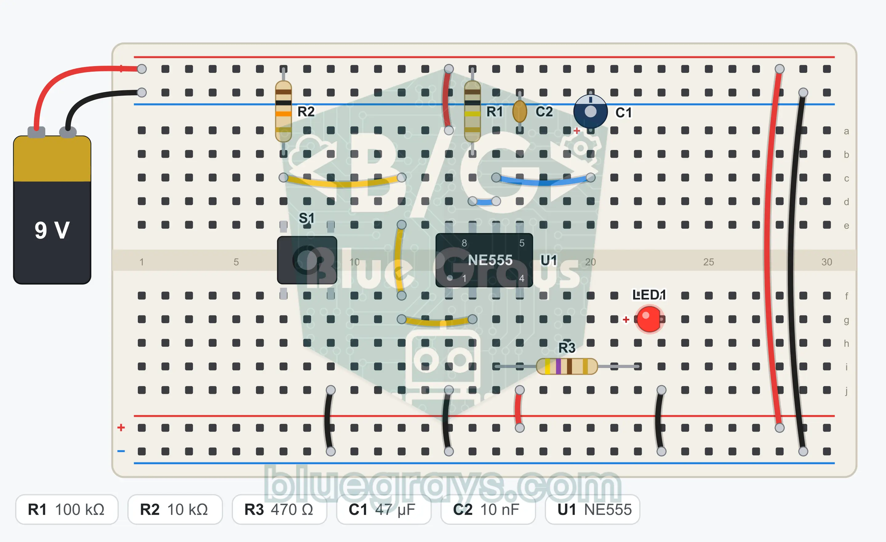
Susun Atur Breadboard
Langkah Pemasangan
- 1
Place the NE555 (U1) over the center gap of the breadboard with its notch facing left. The bottom left corner is pin 1; the bottom row runs 1, 2, 3, 4, and the top row runs 5, 6, 7, 8 from right to left.
- 2
Connect pin 8 to the + rail with a jumper wire.
- 3
Connect pin 1 to the GND (−) rail with a jumper wire.
- 4
Connect pin 4 (reset) to the + rail with a jumper wire.
- 5
Connect pin 6 and pin 7 to each other with a short jumper wire.
- 6
Fit R1 (100 kΩ) between the + rail and pin 7.
- 7
Fit C1 (47 µF): long leg (positive) into the row of pin 6, the short leg on the striped side (negative) into the GND rail.
- 8
Fit R2 (10 kΩ) between the + rail and pin 2. This resistor holds the trigger input high while it is idle.
- 9
Place the push button (S1) next to the IC, over the center gap.
- 10
Connect the leg at one corner of the button to pin 2 with a jumper wire.
- 11
Connect the leg at the diagonally opposite corner of the button to the GND rail with a jumper wire.
- 12
Fit C2 (10 nF) between pin 5 and the GND rail.
- 13
Fit R3 (470 Ω): one end into the row of pin 3, the other end into an empty row.
- 14
Fit LED1: long leg (anode) into the row of R3's free end, short leg (cathode) into the GND rail.
- 15
Plug the red wire of the battery clip into the + rail and the black wire into the GND rail. Compare with the schematic, then snap the battery onto the clip.
Petua: biarkan bateri atau bekalan kuasa tidak disambung semasa membuat pendawaian.
Langkah Ujian
- 1
Connect the battery. The LED must wait unlit. If it lights once at first and goes out after 5 seconds, there is no problem; some 555s trigger themselves at power-on.
- 2
Press the button once briefly and start counting: the LED must light and go out by itself after about 5 seconds.
- 3
Press the button a few more times while the LED is lit: the time must not get longer, and the LED must go out 5 seconds after the first press.
- 4
Hold the button down for 8 seconds: the LED stays lit until you let go, and goes out when you release it.
Cara Ia Berfungsi
In monostable mode the NE555 produces a single pulse at every press of the button: the LED lights for about 5 seconds and goes out by itself. The time is set by R1 and C1.
Standby state
While the button is not pressed, R2 holds pin 2 at 9 V. The output of the 555 is low and the LED is off. Because pin 7 is connected to GND internally, C1 stays discharged.
Triggering
When you press the button, pin 2 drops to GND. The moment the voltage falls below 1/3 of the supply (3 V), the internal flip-flop is set: the output goes high, the LED lights and pin 7 releases the capacitor.
Counting: the capacitor charges
C1 charges slowly through R1. The larger the resistor, the smaller the current and the longer the charging takes. Meanwhile the 555 watches the capacitor voltage on pin 6.
The time is up
When the C1 voltage reaches 2/3 of the supply (6 V), the flip-flop is reset. The output goes low, the LED goes out and pin 7 discharges the capacitor in an instant. The circuit starts waiting for a new press.
Formula
Time
T = 1.1 × R1 × C1
Contoh: 1.1 × 100 kΩ × 47 µF = 5.17 s
Trigger threshold
Vtrig = Vcc / 3
Contoh: 9 V / 3 = 3 V; the time starts when pin 2 falls below this value
End threshold
Vth = 2 × Vcc / 3
Contoh: 2 × 9 V / 3 = 6 V; the time ends when C1 reaches this value
LED current
I = (Vout − VLED) / R3
Contoh: (7.3 V − 2 V) / 470 Ω ≈ 11 mA
Kesilapan Lazim
Nothing happens when I press the button.
Take the button's connections from diagonally opposite corners. Check the direction of the LED and the supply on pin 8 and pin 1.
The LED never goes out.
If R2 is missing or the button is fitted rotated, pin 2 stays low all the time. Also look at the jumper wire between pin 6 and pin 7 and check that C1 is connected.
The LED only flashes at the moment I press.
C1 and C2 have been swapped. The 47 µF goes to pins 6 and 7, the 10 nF to pin 5.
The time is very different from what I expected.
Check the color code of R1 (brown, black, yellow) and the direction of C1. A deviation of up to 20 percent comes from the capacitor tolerance and is normal.
Soalan Lazim
Bagaimanakah saya memanjangkan atau memendekkan masa?
Masa didapati dengan T = 1.1 × R1 × C1. Jika kamu membesarkan R1 atau C1, masa menjadi lebih lama. Jika kamu memasang 220 kΩ di tempat R1, kamu mendapat kira-kira 11 saat, dan dengan 47 kΩ kira-kira 2.4 saat. Untuk beberapa minit, kamu memerlukan nilai besar seperti 1 MΩ dan 100 µF.
Jika saya menekan butang sekali lagi semasa LED menyala, adakah masa menjadi lebih lama?
Tidak. Semasa masa sedang berjalan, NE555 mengabaikan picu baharu; kiraan diteruskan dari tekanan pertama. Apabila kamu menekan selepas masa tamat, 5 saat baharu bermula. Satu-satunya pengecualian ialah apabila butang masih ditekan pada saat masa tamat.
Apakah yang berlaku jika saya menahan butang?
Output kekal tinggi selagi pin 2 kekal rendah. Jadi jika kamu menahan butang lebih lama daripada 5 saat, LED kekal menyala sehingga kamu melepaskannya dan padam sebaik sahaja kamu melepaskannya. Untuk pemasa berfungsi dengan betul, tekan sekejap dan lepaskan sudah memadai.
Mengapakah masanya tidak tepat 5.17 saat?
Pengiraan itu untuk komponen yang ideal. Nilai sebenar kapasitor elektrolitik boleh berbeza daripada nilai bercetaknya sebanyak kira-kira 20 peratus, dan ia juga mempunyai arus bocor yang kecil. Itulah sebabnya keputusan antara 4 dan 6.5 saat adalah normal. Untuk pemasaan yang tepat, kapasitor berkualiti baik dipilih.