
ESP32 Traffic Light
Real traffic light simulation with 3 LEDs red-yellow-green. Timings close to real traffic logic: red long, yellow short, green long. Classic example of sequential GPIO control.

Video
Gambar Rajah Litar

Kod Sumber
1// ─────────────────────────────────────────
2//   BlueGrays · bluegrays.com
3//   ESP32 Traffic Light
4// ─────────────────────────────────────────
5// A traffic light cycle with red, yellow and green LEDs: red 3 s, red +
6// yellow 0.8 s, green 3 s, yellow 0.8 s.
7//
8// Pins:
9//   GPIO 5  -> Red LED
10//   GPIO 18 -> Yellow LED
11//   GPIO 19 -> Green LED
12//   Each LED with a 220 ohm resistor, cathodes to GND
13
14const int RED = 5;      // Red LED pin
15const int YELLOW = 18;  // Yellow LED pin
16const int GREEN = 19;   // Green LED pin
17
18void setup() {
19  pinMode(RED, OUTPUT);
20  pinMode(YELLOW, OUTPUT);
21  pinMode(GREEN, OUTPUT);
22}
23
24void loop() {
25  // Red
26  digitalWrite(RED, HIGH);
27  digitalWrite(YELLOW, LOW);
28  digitalWrite(GREEN, LOW);
29  delay(3000);
30
31  // Red + Yellow
32  digitalWrite(YELLOW, HIGH);
33  delay(800);
34
35  // Green
36  digitalWrite(RED, LOW);
37  digitalWrite(YELLOW, LOW);
38  digitalWrite(GREEN, HIGH);
39  delay(3000);
40
41  // Yellow
42  digitalWrite(GREEN, LOW);
43  digitalWrite(YELLOW, HIGH);
44  delay(800);
45  digitalWrite(YELLOW, LOW);
46}
47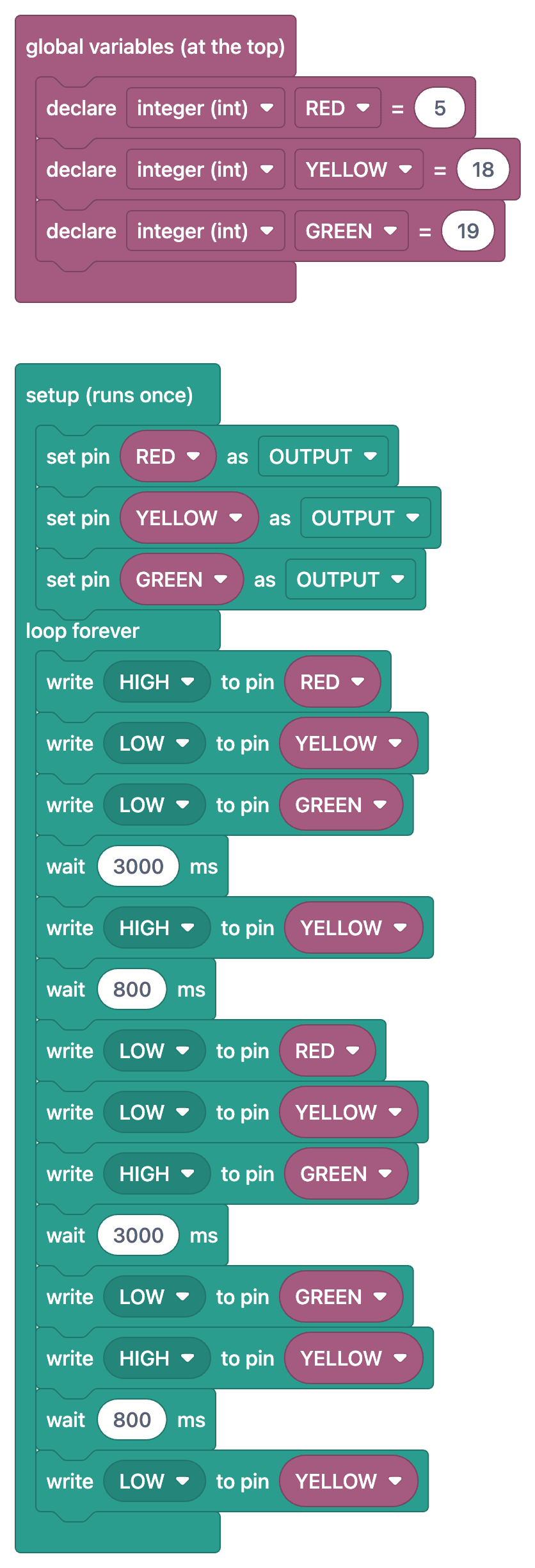
Soalan Lazim
How is it different from the traffic light code on Arduino?
The logic is the same; only the pin numbers differ from the ESP32. Because of the 3.3 V output, the LEDs may glow a bit dimmer; for a brighter result, you can use a 100–150 Ω resistor.
Can I control the traffic light from my phone?
Yes, using the ESP32's Wi-Fi capability, you can set up a small web server and control the lights from a web browser. This is the biggest feature that sets the ESP32 apart from the Arduino.
How can I make the durations realistic?
At real intersections, the green and red lights stay on for 20–60 seconds, and the yellow light stays on for 3–4 seconds. During the test, you can shorten the wait times and then set them to the actual values for the presentation.
Which pins should I select?
Select pins such as GPIO 25, 26, and 27 that have no specific function during startup. Since GPIO 0, 2, 12, and 15 affect the boot mode, circuits connected to them may prevent the board from booting.