
555 and 4017 Running Light: 10 LEDs with Adjustable Speed
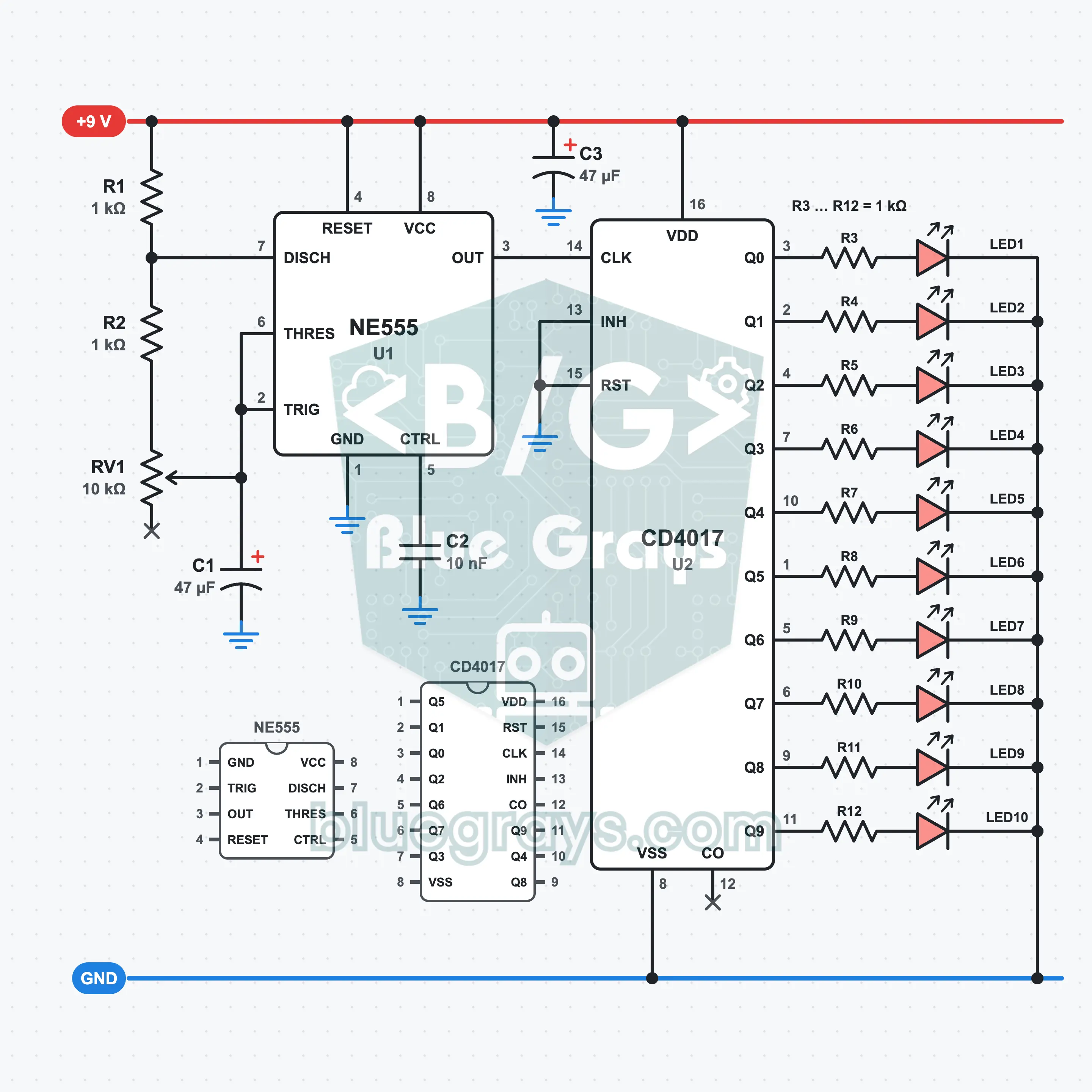
Free the running light from the button: the NE555 produces the clock pulses itself, and the CD4017 counts these pulses and lights ten LEDs one after another. You set the speed with a potentiometer; the light completes one lap in about 1 second at the fastest setting and in 7.5 seconds at the slowest. You learn how to link two ICs with a clock line, how to change the frequency of an oscillator with a resistance and what a supply capacitor is for.
Video
Gambar Rajah Litar
Susun Atur Breadboard
Langkah Pemasangan
- 1
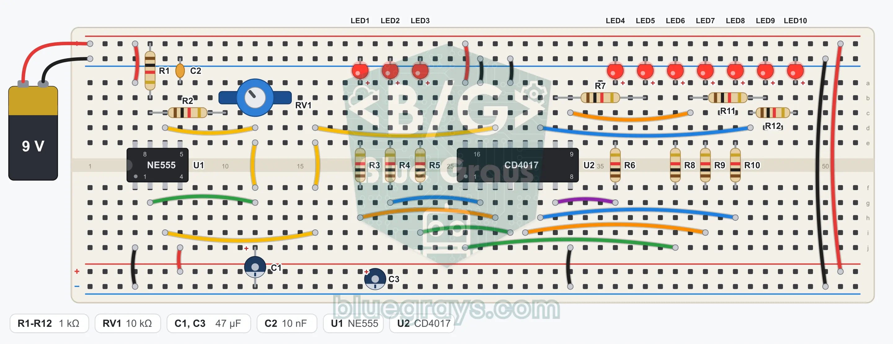
Place the NE555 (U1) over the center gap, at the left end of the breadboard, from row 4 to row 7, with its notch facing left. The pin at the bottom left corner is pin 1; the bottom row runs 1, 2, 3, 4 from left to right, and the top row runs 5, 6, 7, 8 from right to left.
- 2
Connect pin 8 of the 555 (row 4, top half) to the top + rail with a jumper wire, its pin 1 (row 4, bottom half) to the bottom GND (−) rail with a jumper wire, and its pin 4 (row 7, bottom half) to the bottom + rail with a jumper wire.
- 3
Fit R1 (1 kΩ) between the top + rail and the row of pin 7 of the 555 (row 5, top half). Fit C2 (10 nF, marked 103) between the row of pin 5 (row 7, top half) and the top GND rail.
- 4
Fit R2 (1 kΩ) between the top half of row 5 and the top half of row 10. Place the RV1 potentiometer so that its three legs sit in rows 10, 12 and 14 in the top half: the left leg is in the same row as R2, and the middle leg is in row 12. The right leg stays unconnected; do not plug anything else into the top half of row 14.
- 5
Connect pin 6 of the 555 (row 6, top half) to the top half of row 12 with a jumper wire. With a short jumper wire, connect the top half of row 12 to the bottom half of the same row; the jumper wire passes over the center gap. Connect pin 2 (row 5, bottom half) to the bottom half of row 12 with a jumper wire.
- 6
Fit C1 (47 µF): its long leg (+) goes into the bottom half of row 12, and the short leg next to the stripe on its body into the bottom GND rail.
- 7
Place the CD4017 (U2) over the center gap, from row 26 to row 33, with its notch facing left. The pin at the bottom left corner is pin 1; the bottom row runs from 1 to 8 from left to right, and the top row runs from 9 to 16 from right to left.
- 8
Connect pin 16 of the CD4017 (row 26, top half) to the top + rail with a jumper wire. Connect pin 15 (row 27, top half) and pin 13 (row 29, top half) to the top GND rail with one jumper wire each, and pin 8 (row 33, bottom half) to the bottom GND rail with a jumper wire.
- 9
Build the clock line with three jumper wires: from pin 3 of the 555 (row 6, bottom half) to the bottom half of row 16; from the bottom half of row 16 over the gap to the top half of the same row; from the top half of row 16 to pin 14 of the CD4017 (row 28, top half).
- 10
Line up the ten LEDs along the top edge: the long leg (anode) of each LED goes into the top hole of its row, and the short leg (cathode) into the top GND rail right above it. LED1, LED2 and LED3 go into rows 19, 21 and 23 in that order; the seven LEDs from LED4 to LED10 go into rows 36, 38, 40, 42, 44, 46 and 48 in that order.
- 11
Fit seven 1 kΩ resistors over the center gap, from the bottom half to the top half of the same row: R3 in row 19, R4 in row 21, R5 in row 23, R6 in row 36, R8 in row 40, R9 in row 42, R10 in row 44.
- 12
Connect the three LEDs to the left of the CD4017 from the bottom half: pin 3 (row 28) to the bottom half of row 19 with a jumper wire, pin 2 (row 27) to the bottom half of row 21, pin 4 (row 29) to the bottom half of row 23.
- 13
Connect four of the LEDs on the right from the bottom half as well: pin 7 (row 32) to the bottom half of row 36 with a jumper wire, pin 1 (row 26) to the bottom half of row 40, pin 5 (row 30) to the bottom half of row 42, pin 6 (row 31) to the bottom half of row 44.
- 14
The remaining three LEDs are connected from the top half. Fit R7 (1 kΩ) between the row of pin 10 (row 32) and row 38. Connect pin 9 (row 33) to row 41 with a jumper wire, and fit R11 between row 41 and row 46. Connect pin 11 (row 31) to row 45 with a jumper wire, and fit R12 between row 45 and row 48. Pin 12 stays unconnected.
- 15
Fit C3 (47 µF) between the bottom + rail and the bottom GND rail, level with row 20: its long leg goes into the + rail. At the right end of the breadboard, connect the top + rail to the bottom + rail and the top GND rail to the bottom GND rail with one jumper wire each.
- 16
Plug the red wire of the battery clip into the top + rail and the black wire into the top GND rail. Compare the connections with the schematic and with the pinouts once, then snap the battery onto the clip.
Petua: biarkan bateri atau bekalan kuasa tidak disambung semasa membuat pendawaian.
Langkah Ujian
- 1
Connect the battery: the light must start running by itself. The LEDs light one after another from left to right, and after LED10 the light returns to LED1.
- 2
Turn the potentiometer all the way to one end: the light must speed up and complete one lap in about 1 second. Turn it to the other end: each LED must stay lit for about 0.75 seconds, and one lap must take 7.5 seconds.
- 3
At the slowest setting, time one lap with a clock. Because electrolytic capacitors have a wide tolerance, a result between 6 and 9 seconds is normal.
- 4
Pull out the GND rail end of the jumper wire on pin 13 of the CD4017 and plug it into the top + rail: the light must freeze on the LED where it is. When you plug the jumper wire back into the GND rail, the light goes on running from where it stopped.
Cara Ia Berfungsi
The NE555 produces regular clock pulses, and on every pulse the CD4017 moves the lit LED one step forward. The potentiometer sets the clock frequency, that is, the speed at which the light runs.
Two ICs, two jobs
The work is divided up in this circuit. The NE555 only keeps the tempo: its output swings between 0 and 1 at regular intervals. The CD4017 only counts: on every rising edge that arrives at its clock input, it shifts the output that is 1 to the next one. The only path that links the two is the clock line that runs from pin 3 of the 555 to pin 14 of the CD4017.
How does the 555 produce the clock?
C1 charges through R1, R2 and the potentiometer. When its voltage reaches 6 V, the 555 pulls its output low and connects pin 7 to GND inside the IC; this time C1 discharges through R2 and the potentiometer. When the voltage falls to 3 V, the output goes high again and the cycle starts over. Each cycle is one clock pulse.
How does the potentiometer change the speed?
The potentiometer is an adjustable resistor connected in series with R2. As its resistance grows, C1 charges and discharges more slowly, the pulses get further apart and the light slows down. The clock is 10.2 Hz when the resistance is zero and 1.33 Hz when it is 10 kΩ. R2 stays in the path as a fixed 1 kΩ; even if the shaft reaches its end stop, the discharge current is limited.
One lap in ten pulses
Because the CD4017 has ten outputs, it takes exactly ten clock pulses for the light to return to the LED it started from. That is why the lap time is ten times the clock period: about 1 second at the fastest setting and 7.5 seconds at the slowest. The reset (pin 15) and clock inhibit (pin 13) inputs are held at GND so that the counter counts without interruption.
Why are C2 and C3 there?
Both keep the circuit stable. C2 protects the internal threshold voltage of the 555 from supply noise; the clock intervals stay even. C3 supplies the momentary current the 555 draws when its output changes. If this current makes the supply rail dip, the CD4017 can count extra pulses; C3 prevents this.
Formula
Clock frequency
f = 1.44 / ((R1 + 2 × (R2 + RV1)) × C1)
Contoh: With RV1 = 0: 1.44 / (3 kΩ × 47 µF) = 10.2 Hz; with RV1 = 10 kΩ: 1.44 / (23 kΩ × 47 µF) = 1.33 Hz
Time one LED stays lit (clock period)
T = 1 / f
Contoh: 1 / 10.2 Hz ≈ 98 ms (fastest setting); 1 / 1.33 Hz ≈ 0.75 s (slowest setting)
One full lap
t = 10 × T
Contoh: 10 × 98 ms ≈ 1 s; 10 × 0.75 s = 7.5 s
High and low times of the clock
t1 = 0.693 × (R1 + R2 + RV1) × C1; t2 = 0.693 × (R2 + RV1) × C1
Contoh: With RV1 = 10 kΩ: t1 = 0.693 × 12 kΩ × 47 µF = 0.39 s and t2 = 0.693 × 11 kΩ × 47 µF = 0.36 s
LED current (upper limit)
I = (Vout − VLED) / R
Contoh: (9 V − 2 V) / 1 kΩ = 7 mA; because the CD4017 output drops under load, the real current is a few milliamps lower
Kesilapan Lazim
A single LED stays lit and the light does not run.
Follow the clock line: pin 3 of the 555 must reach pin 14 of the CD4017 through row 16. Pin 4 of the 555 must also be on the + rail.
All the LEDs are dimly lit at the same time.
The clock is running too fast for the eye to follow. C1 must be the 47 µF electrolytic capacitor; if the 10 nF C2 has been fitted in its place, swap the two.
The speed does not change with the potentiometer.
The middle leg must be in row 12 and the left leg in the same row as R2 (row 10). The legs may have shifted by one row.
C1 or C3 heats up.
The electrolytic capacitor is fitted backwards. Disconnect the battery at once; the stripe on the body must face the GND side.
Soalan Lazim
How is this circuit different from the running light with a button?
In the button version you give the clock pulse yourself; the light takes one step on every press, and extra parts are needed to filter out the switch bounce. Here the 555 produces the pulse: the light runs by itself, always at the same pace, and the potentiometer sets the pace. Because the output of the 555 is a clean square wave, no debounce filter is needed.
The range of the potentiometer is not enough; can I make the light even faster?
Change C1. If you fit 10 µF, everything gets about five times faster; at the fastest setting the light completes one lap in a fifth of a second and the eye can hardly pick out the LEDs one by one. If you fit 100 µF, the speed drops to half, and at the slowest setting one lap takes about 16 seconds. Pay attention to the direction when you fit an electrolytic capacitor.
Why are only two of the three legs of the potentiometer connected?
Here the potentiometer works as an adjustable resistor, not as a voltage divider. The resistance between one outer leg and the middle leg changes between 0 and 10 kΩ as you turn the shaft, and that is what the circuit needs. The other outer leg is left unconnected. R2, in turn, keeps the total resistance from falling to zero when the shaft reaches its end stop.
Wouldn't the circuit work without the capacitor C3?
Most of the time it works, but it is not reliable. Every time the 555 changes its output it draws a short, sharp current from the battery; this causes a small dip on the supply rail. The CD4017 can take this dip for an extra clock pulse, and the light skips an LED now and then. C3 delivers that momentary current itself and keeps the rail steady.