
Nyalakan LED dengan butang tekan
Tambah butang tekan pada litar pertamamu: LED menyala apabila kamu menekannya dan padam apabila kamu melepaskannya. Butang adalah seperti jambatan; menekannya melengkapkan laluan, melepaskannya membuka laluan. Kamu merasai perbezaan antara litar terbuka dan litar tertutup di hujung jarimu. Kamu juga belajar kaki mana pada butang empat kaki yang bersambung di dalam dan cara ia diletakkan pada breadboard.
Video
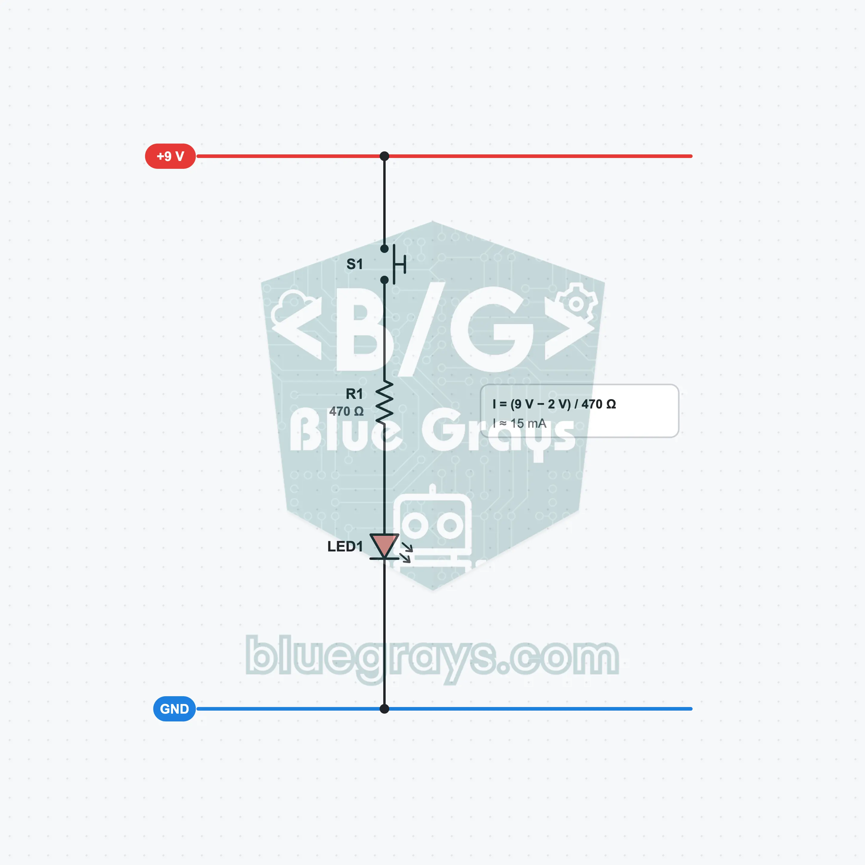
Gambar Rajah Litar
Susun Atur Breadboard
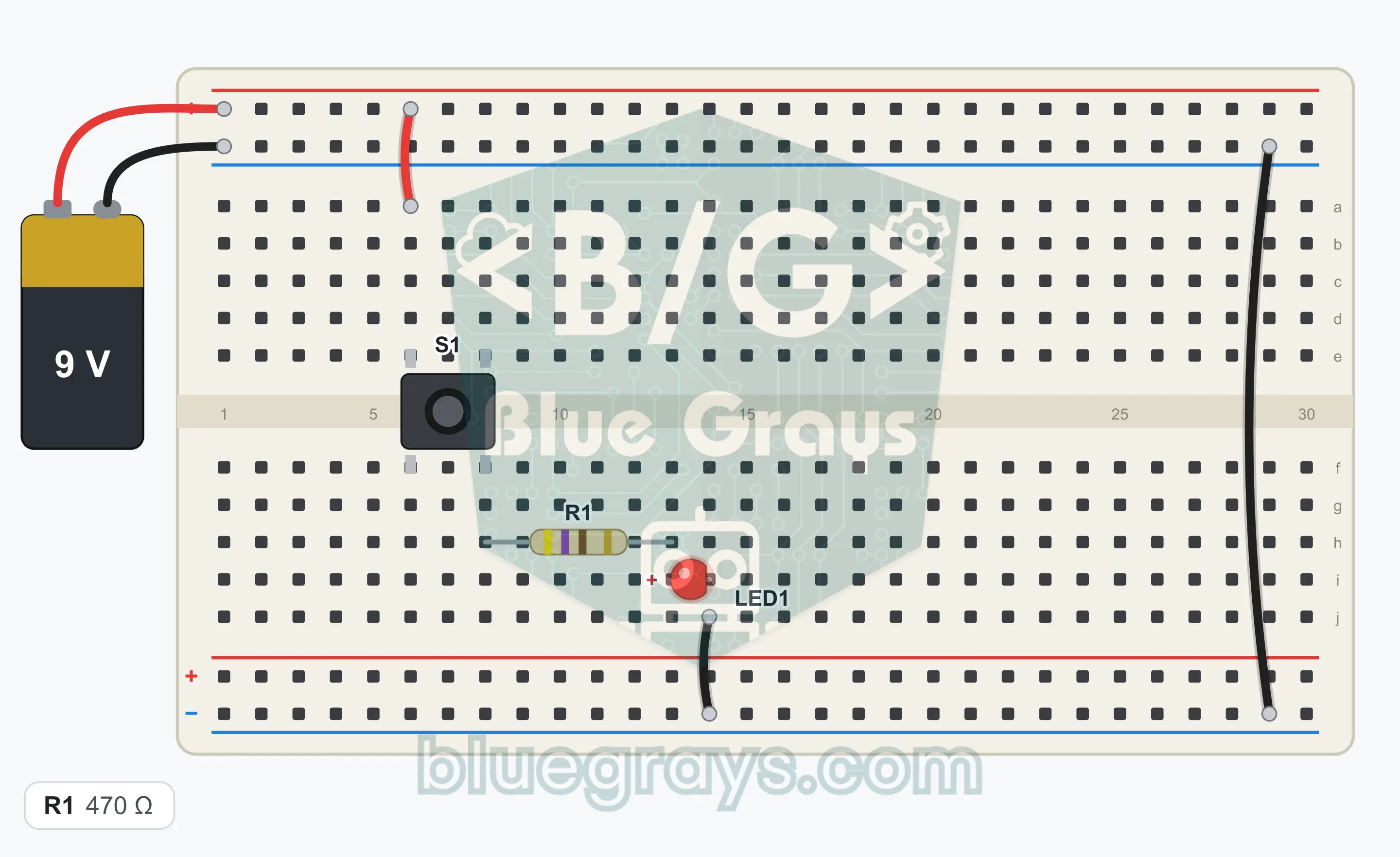
Langkah Pemasangan
- 1
Place the S1 button over the center gap: its left legs go into row 6 and its right legs into row 8. Two legs stay in the top half, two legs in the bottom half. Push the button down until it is fully seated.
- 2
Connect the top + rail to the top half of row 6 with a jumper wire. This is the row of the button's top left leg.
- 3
Plug one leg of R1 (470 Ω; yellow, violet, brown) into the bottom half of row 8, that is, the row of the button's bottom right leg.
- 4
Plug the other leg of R1 into row 13 in the bottom half.
- 5
Plug the long leg of LED1 into row 13 in the bottom half, the same row as the leg of R1.
- 6
Plug the short leg of LED1 into row 14 right next to it.
- 7
Connect the bottom half of row 14 to the bottom GND (−) rail with a jumper wire.
- 8
Connect the top GND rail to the bottom GND rail with a jumper wire (at the right end of the breadboard, level with row 29). Because the battery will be connected to the top rails, the bottom rail becomes GND through this bridge.
- 9
Plug the red wire of the battery clip into the top + rail and the black wire into the top GND (−) rail. Compare the connections with the schematic once, then snap the battery onto the clip.
Petua: biarkan bateri atau bekalan kuasa tidak disambung semasa membuat pendawaian.
Langkah Ujian
- 1
Connect the battery and do not touch the button: LED1 must stay off.
- 2
Press S1 and hold it: LED1 lights and stays on until you lift your finger.
- 3
Release the button: LED1 goes out immediately.
- 4
Press the button quickly several times in a row: the LED must respond to every press without delay.
Cara Ia Berfungsi
The button opens and closes the path between the + rail and the resistor. While it is pressed the LED lights with about 15 mA; when you release it the current stops and the LED goes out.
A button is a bridge
Inside the button there are two metal terminals that do not touch each other and a spring-loaded cap above them. When you press, the cap joins the two terminals; when you release, the spring pushes the cap back. So the button is a small bridge that you open and close with your finger.
Open circuit
While the button is not pressed, the path coming from the + rail ends at the button. Because there is no unbroken path for current to flow, no current passes through R1 and LED1 at all. This state is called an open circuit; the battery is not used either.
Closed circuit
When you press the button the path is completed: the + rail, S1, R1, LED1 and GND. The current is (9 V − 2 V) / 470 Ω ≈ 15 mA, as in the first circuit. Because the button is a good conductor, no voltage drops across it and the brightness does not change.
Diagonal legs
The top and bottom legs of the button in the same row are connected inside. If you use the top left and bottom right legs, the button works correctly whichever way around it is fitted. That is why the + jumper wire goes into the top half of row 6 and R1 into the bottom half of row 8.
Jadual Kebenaran
| S1 | Circuit | LED1 |
|---|---|---|
| Released | Open | Off |
| Pressed | Closed | On |
The button completes the path only for as long as it is held down.
Formula
LED current (S1 pressed)
I = (Vbat − VLED) / R1
Contoh: (9 V − 2 V) / 470 Ω ≈ 15 mA
LED current (S1 released)
I = 0
Contoh: Because the path is open, no current flows; the battery is not used
Kesilapan Lazim
The LED does not light when you press the button.
The bridge jumper that joins the top and bottom GND rails is missing, or the LED is fitted backwards.
The LED lights without the button being pressed.
The + jumper wire and R1 are plugged into the row with the same number. The jumper wire must be in the top half of row 6, R1 in the bottom half of row 8.
The LED does not react at all, and the connections are correct.
The button is not fully seated. Place it upright over the gap and push it all the way down.
Soalan Lazim
Mengapakah butang mempunyai empat kaki?
Sebenarnya hanya ada dua terminal di dalam; setiap terminal keluar sebagai satu kaki pada setiap sisi badan butang. Empat kaki membuatkan butang duduk dengan kukuh pada papan. Pada breadboard, kaki yang jatuh dalam baris yang sama di kedua-dua belah celah bersambung antara satu sama lain; apabila kamu menekan butang, dua baris itu tersambung.
Bolehkah saya meletakkan butang selepas LED, di sisi GND?
Boleh. Butang, perintang dan LED bersiri; dalam litar bersiri, urutannya tidak penting. Di mana-mana sahaja ia berada pada laluan, tiada arus boleh mengalir semasa butang terbuka, dan 15 mA yang sama mengalir semasa ia tertutup. Satu-satunya peraturan yang tidak berubah ialah arah LED: anod mesti sentiasa menghadap ke sisi +.
Bagaimanakah saya mengekalkan LED menyala selepas melepaskan butang?
Butang tekan bersifat sementara; spring di dalamnya membuka sesentuh sebaik sahaja kamu mengangkat jari. Untuk mengekalkan LED menyala, kamu memerlukan sama ada suis gelongsor yang mengekalkan kedudukannya atau litar memori yang mengingati keadaan. Kamu akan membina kedua-duanya dalam litar siri ini yang kemudian.
Adakah litar menggunakan bateri semasa butang tidak ditekan?
Tidak. Semasa butang terbuka, laluan terputus dan tiada arus langsung mengalir, jadi bateri tidak susut. Arus hanya mengalir selama kamu menekan butang. Litar ini boleh menunggu berhari-hari dengan bateri bersambung; namun, menanggalkan bateri daripada klip apabila selesai ialah tabiat yang baik.