
Pengelip 555: litar LED berkelip
Tiada kod, tiada papan: dengan satu IC NE555, tiga perintang dan dua kapasitor, buat LED berkelip kira-kira sekali sesaat. Litar ini ialah mod astabil 555, iaitu mod larian bebasnya. Kamu melihat kapasitor mengecas dan menyahcas, ambang 1/3 dan 2/3 serta formula frekuensi dalam litar yang kamu bina sendiri. Kamu juga mencuba bagaimana kelajuan berubah apabila kamu menukar perintang atau kapasitor.
Video
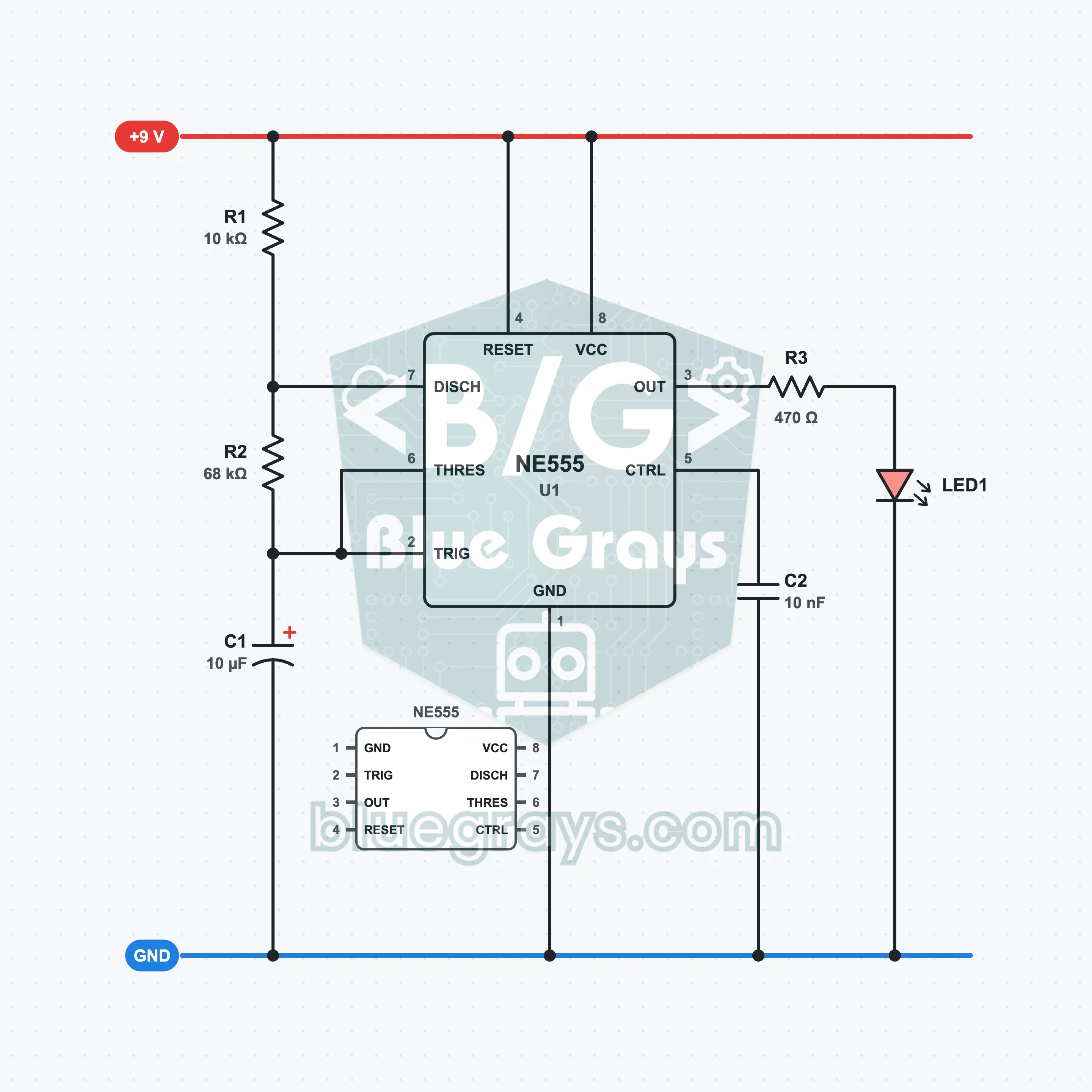
Gambar Rajah Litar
Susun Atur Breadboard
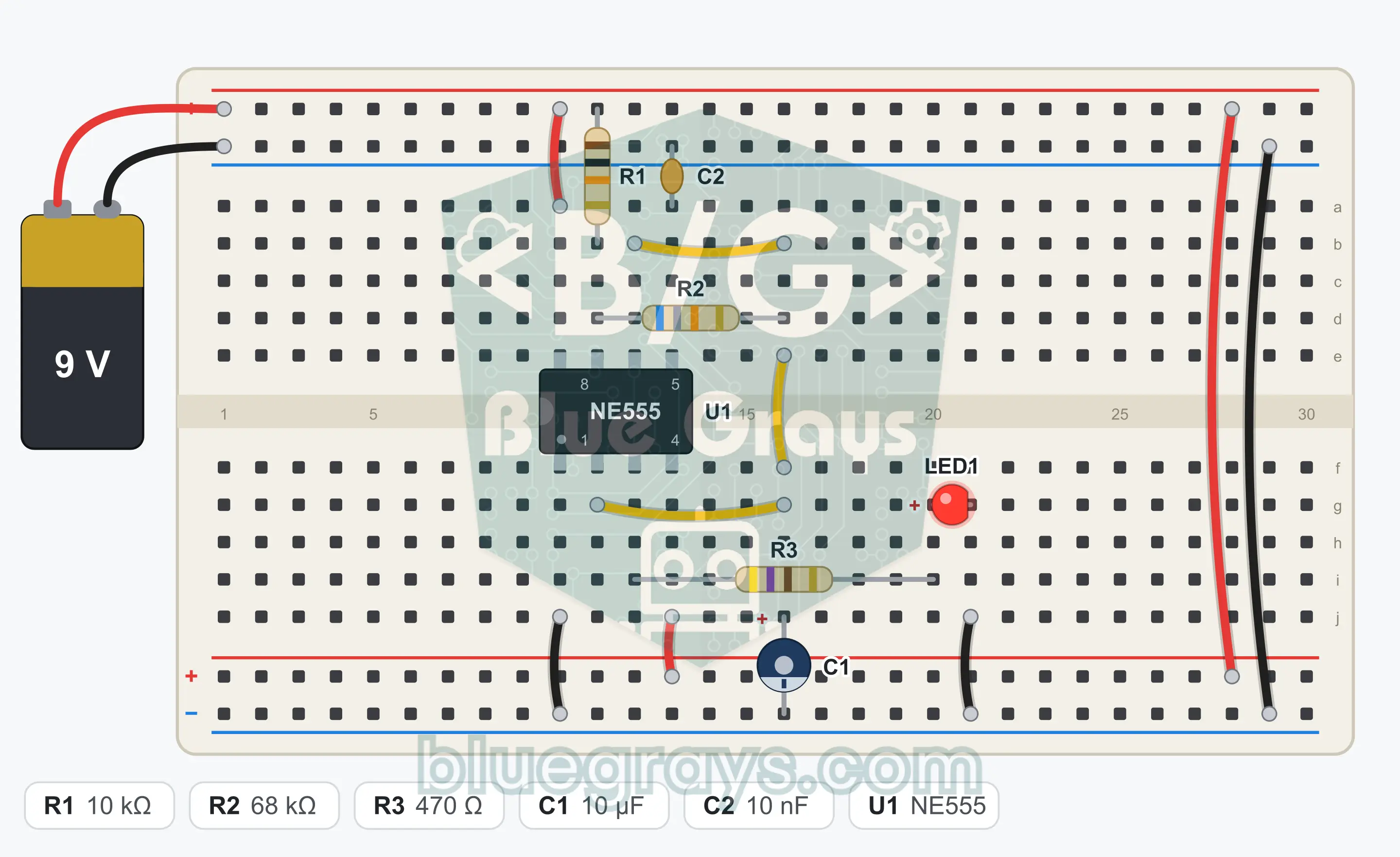
Langkah Pemasangan
- 1
Place the NE555 (U1) over the center gap of the breadboard with its notch facing left. The pin at the bottom left corner is pin 1; the bottom row runs 1, 2, 3, 4 from left to right, and the top row runs 5, 6, 7, 8 from right to left.
- 2
Connect pin 8 to the + rail of the breadboard with a jumper wire.
- 3
Connect pin 1 to the GND (−) rail with a jumper wire.
- 4
Connect pin 4 (reset) to the + rail with a jumper wire. This way the IC runs all the time.
- 5
Connect pin 2 and pin 6 to each other with a jumper wire.
- 6
Fit R1 (10 kΩ) between the + rail and pin 7.
- 7
Fit R2 (68 kΩ) between pin 7 and pin 6.
- 8
Fit C1 (10 µF): long leg (positive) into the row of pin 6, the short leg on the striped side (negative) into the GND rail.
- 9
Fit C2 (10 nF) between pin 5 and the GND rail. It has no polarity.
- 10
Fit R3 (470 Ω): one end into the row of pin 3, the other end into an empty row.
- 11
Fit LED1: long leg (anode) into the row of R3's free end, short leg (cathode) into the GND rail.
- 12
Plug the red wire of the battery clip into the + rail and the black wire into the GND rail. Compare the connections with the schematic once, then snap the battery onto the clip.
Petua: biarkan bateri atau bekalan kuasa tidak disambung semasa membuat pendawaian.
Langkah Ujian
- 1
Connect the battery: the LED must start flashing right away.
- 2
Count 10 flashes and time them: it must take about 10 seconds.
- 3
Watch closely: the time the LED stays on is a little longer than the time it stays off.
- 4
Pull the + rail end of the jumper wire on pin 4 out and plug it into the GND rail: the LED goes out and the flashing stops. When you plug the jumper wire back into the + rail, the LED starts flashing again.
Cara Ia Berfungsi
In astable mode the NE555 generates a square wave by itself and flashes the LED about once a second. The speed is set by R1, R2 and C1.
What is inside the 555?
Inside there are two comparators, a flip-flop and a discharge transistor. The comparators compare the capacitor voltage with 1/3 and 2/3 of the supply. With a 9 V battery these thresholds are 3 V and 6 V.
Charging: the LED lights
While the output (pin 3) is high, the LED is lit. Meanwhile C1 charges from the + rail through R1 and R2. When its voltage reaches 6 V, pin 6 senses this, the flip-flop flips and the output goes low.
Discharging: the LED goes out
When the output goes low, pin 7 is connected to GND internally. C1 now discharges through R2 alone. When its voltage falls to 3 V, pin 2 is triggered, the output goes high again and the cycle starts over.
What sets the speed?
The larger the capacitor and the higher the resistors, the longer charging and discharging take. In this circuit the on time is 0.54 seconds and the off time is 0.47 seconds; together they add up to about 1 second.
What are C2 and R3 for?
C2 protects the control input on pin 5 from noise and keeps the times from drifting. R3 limits the current through the LED to about 11 mA; without it the LED would fail in a short time.
Formula
On time (output high)
t1 = 0.693 × (R1 + R2) × C1
Contoh: 0.693 × (10 kΩ + 68 kΩ) × 10 µF = 0.54 s
Off time (output low)
t2 = 0.693 × R2 × C1
Contoh: 0.693 × 68 kΩ × 10 µF = 0.47 s
Frequency
f = 1.44 / ((R1 + 2 × R2) × C1)
Contoh: 1.44 / ((10 kΩ + 2 × 68 kΩ) × 10 µF) = 0.99 Hz, that is, about once a second
LED current
I = (Vout − VLED) / R3
Contoh: (7.3 V − 2 V) / 470 Ω ≈ 11 mA (the output of the 555 is about 1.7 V below the supply)
Kesilapan Lazim
The LED does not light at all.
You may have fitted the LED backwards: the long leg goes to R3, the short leg to GND. Also check that pin 8 is connected to the + rail and pin 1 to the GND rail.
The LED is lit all the time and does not go out.
The jumper wire between pin 2 and pin 6 is missing, or C1 is not connected to this pair. Make sure R2 is between pin 7 and pin 6.
The LED flickers or looks as if it is always lit.
C1 and C2 may have been swapped. The 10 µF electrolytic capacitor must be on pin 6 and the 10 nF ceramic capacitor on pin 5.
The IC heats up.
Disconnect the battery at once. The 555 may be fitted backwards, or R1 may have been left out and pin 7 connected directly to the + rail.
Soalan Lazim
Bagaimanakah saya menukar kelajuan kelipan LED?
Kelajuan ditetapkan oleh C1 dan R2. Jika kamu membesarkan C1 atau menaikkan R2, LED menjadi perlahan; jika kamu mengecilkannya, ia menjadi pantas. Contohnya, jika kamu memasang 22 µF di tempat C1, LED berkelip kira-kira sekali setiap 2.2 saat, dan dengan 4.7 µF kira-kira sekali setiap setengah saat.
Bolehkah saya menggunakan bekalan lain dan bukannya bateri 9 V?
Boleh. NE555 berfungsi antara 4.5 V dan 16 V. Dengan 5 V atau 6 V, litar yang sama berkelip pada kelajuan yang sama, kerana ambang bergerak bersama sebagai 1/3 dan 2/3 daripada voltan bekalan. LED hanya menyala sedikit lebih malap.
Adakah kapasitor 10 nF pada pin 5 benar-benar perlu?
Litar juga berfungsi tanpanya. Pin 5 ialah input kawalan yang menuju ke ambang 2/3 dalaman. Jika ia dibiarkan terapung, hingar di sekeliling boleh mengalihkan ambang dan masa beralih sedikit. Kapasitor 10 nF menyalirkan hingar ini ke GND; biasakan diri untuk sentiasa memasangnya.
Mengapakah LED tidak berkelip tepat separuh menyala, separuh padam?
Kapasitor mengecas melalui R1 dan R2 tetapi menyahcas melalui R2 sahaja. Oleh sebab laluan pengecasan mempunyai rintangan yang lebih tinggi, masa menyala LED (0.54 s) sedikit lebih lama daripada masa padamnya (0.47 s). Semakin kecil R1 berbanding R2, semakin hampir kedua-dua masa itu.