
555 flip-flop: ikki tugmali xotira sxemasi
Bir tugmani bos, LED yonadi; barmog‘ingni olsang ham yonib qoladi. Ikkinchi tugmani bos, u o‘chadi. NE555 ning bistabil rejimi uning ichidagi flip-flopdan to‘g‘ridan-to‘g‘ri foydalanadi: kondensator bilan vaqt sanash yo‘q, faqat SET va RESET. Bu sxema 1 bitli xotiraning yig‘ish eng oson ko‘rinishi va flip-flop mantig‘ini birinchi marta ko‘rish uchun ajoyib.
Video
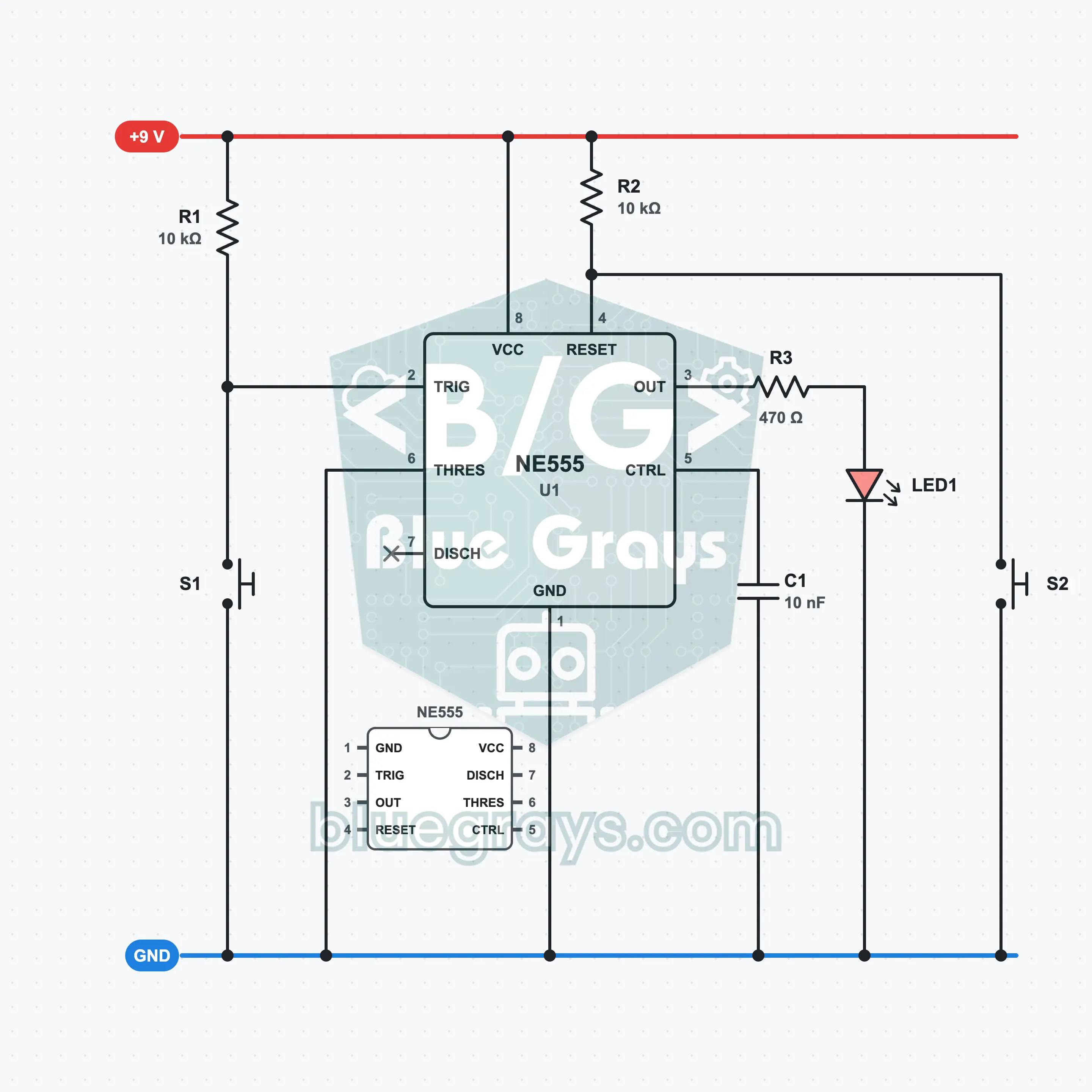
Elektr sxemasi
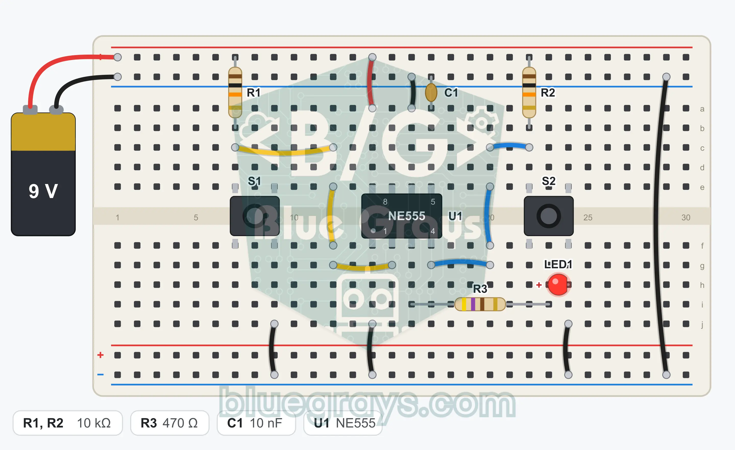
Breadboard joylashuvi
O‘rnatish qadamlari
- 1
Place the NE555 (U1) over the center gap of the breadboard with its notch facing left. The bottom left corner is pin 1; the bottom row runs 1, 2, 3, 4, and the top row runs 5, 6, 7, 8 from right to left.
- 2
Connect pin 8 to the + rail with a jumper wire.
- 3
Connect pin 1 to the GND (−) rail with a jumper wire.
- 4
Connect pin 6 to the GND rail with a jumper wire. The threshold input is not used in this circuit.
- 5
Fit R1 (10 kΩ) between the + rail and pin 2.
- 6
Fit R2 (10 kΩ) between the + rail and pin 4.
- 7
Place the S1 button over the center gap and connect the leg at one corner to pin 2 with a jumper wire.
- 8
Connect the leg at the diagonally opposite corner of S1 to the GND rail with a jumper wire.
- 9
Place the S2 button over the center gap and connect the leg at one corner to pin 4 with a jumper wire.
- 10
Connect the leg at the diagonally opposite corner of S2 to the GND rail with a jumper wire.
- 11
Fit C1 (10 nF) between pin 5 and the GND rail.
- 12
Fit R3 (470 Ω): one end into the row of pin 3, the other end into an empty row.
- 13
Fit LED1: long leg (anode) into the row of R3's free end, short leg (cathode) into the GND rail.
- 14
Pin 7 stays unconnected. Plug the red wire of the battery clip into the + rail and the black wire into the GND rail, compare with the schematic and snap the battery onto the clip.
Maslahat: ulanishlarni qilayotganda batareya yoki quvvat manbaini ulama.
Sinov qadamlari
- 1
Connect the battery. The LED may start lit or unlit; both are normal.
- 2
Press S1 once briefly and release it: the LED must light and stay lit.
- 3
Press S2 once briefly and release it: the LED must go out and stay off.
- 4
Press S1 several times in a row: if the LED is already lit, nothing must change.
- 5
Press both buttons together: the LED goes out, because reset is dominant.
Qanday ishlaydi
In bistable mode the NE555 works like a 1-bit memory: S1 lights the LED, S2 turns it off, and the state is kept after you release the button.
The flip-flop inside the 555
Inside the NE555 there is an SR flip-flop that controls the output. In the timer modes this flip-flop is set and reset by the capacitor voltage. In bistable mode you take the capacitor out of the picture and control the flip-flop yourself with the buttons.
S1: set (SET)
R1 holds pin 2 at 9 V while it is idle. When you press S1, pin 2 drops to GND. When the voltage falls below 1/3 of the supply (3 V), the flip-flop is set, the output goes high and the LED lights. When you release the button, the state does not change.
S2: reset (RESET)
R2 holds pin 4 at 9 V while it is idle. When you press S2, pin 4 drops to GND and below about 0.7 V the flip-flop is reset. The output goes low, the LED goes out and it stays that way until a new SET arrives.
Why is there no capacitor?
Because pin 6 is at GND, the threshold comparator never comes into play; the circuit does not count time. That is also why pin 7 is left unconnected. The only capacitor is C1, the 10 nF that protects pin 5 from noise.
Haqiqat jadvali
| S1 (SET) | S2 (RESET) | Output (LED) |
|---|---|---|
| Not pressed | Not pressed | Previous state is kept |
| Pressed | Not pressed | 1 (lights) |
| Not pressed | Pressed | 0 (goes out) |
| Pressed | Pressed | 0 (reset dominant) |
Pressing a button pulls the related pin to GND; both inputs are active-low.
Formulalar
SET threshold
Vtrig = Vcc / 3
Misol: 9 V / 3 = 3 V; the output goes high when pin 2 falls below this value
Current through the resistor while the button is pressed
I = Vcc / R1
Misol: 9 V / 10 kΩ = 0.9 mA
LED current
I = (Vout − VLED) / R3
Misol: (7.3 V − 2 V) / 470 Ω ≈ 11 mA
Ko‘p uchraydigan xatolar
The LED does not light when I press S1.
If R2 is missing, the 555 stays in reset all the time. Check that pin 4 is connected to the + rail through 10 kΩ, and check the direction of the LED.
The LED goes out when I release the button.
Pin 6 is not connected to GND. Connect it directly to the GND rail with a short jumper wire.
S2 does not turn the LED off.
Take the button's connections from diagonally opposite corners; the two legs on the same side are already connected inside.
The LED changes by itself when touched.
R1 or R2 is not seated properly. A floating input picks up noise from the surroundings; plug both resistors firmly into the + rail.
Ko‘p so‘raladigan savollar
Nega bu sxema flip-flop hisoblanadi?
Flip-flop ikkita barqaror holati bor va o‘ziga berilgan oxirgi buyruqni eslab qoladigan sxema. Bu yerda chiqish yo yuqori, yo past bo‘ladi va tugma bosmaguningcha o‘zgarmaydi. S1 o‘rnatish (SET), S2 esa tiklash (RESET) vazifasini bajaradi; boshqacha aytganda, bu SR trigger (flip-flop).
Ikkala tugmani birga bossam nima bo‘ladi?
Reset yutadi. NE555 da 4-pin past turgan ekan, trigger kirishi nima bo‘lishidan qat’i nazar chiqish past qoladi va LED o‘chadi. S1 hali bosilgan holda avval S2 ni qo‘yib yuborsang, LED yonadi; avval S1 ni qo‘yib yuborsang, LED o‘chiq qoladi.
Nega 6-pin GND ga ulangan?
6-pin chegara kirishi; uning kuchlanishi manbaning 2/3 qismidan oshsa, chiqishni past qiladi. Bistabil rejimda vaqt sanamaganimiz uchun bu kirish hech qachon ishga tushmasligini xohlaymiz. Uni GND ga ulash chegara komparatorini ishdan chiqarib qo‘yadi.
Batareyani ulaganimda LED yoniq yoki o‘chiq holda boshlanadimi?
Kafolat yo‘q; quvvat yoqilganda ichki flip-flop ikki holatidan biriga tushadi. Ko‘pincha o‘chiq holda boshlanadi, lekin yoniq holda ham boshlanishi mumkin. Aniq o‘chiq boshlanishini istasang, 4-pin bilan GND orasiga 100 nF li kondensator qo‘sh: u yoqilganda qisqa reset hosil qiladi.