
101 ta sxema
Asosiy elektron sxemalar
Asosiy elektron sxemalar Arduino kabi platasiz va bitta qator kodsiz yig‘iladigan sxemalardir. Breadboard, batareya, bir nechta rezistor va LED bilan boshlaysan; keyin tranzistor sxemalari, 555 taymer sxemalari, mantiqiy elementlar, trigger va sanagich sxemalari bilan davom etasan. Kompyuter ham, kavsharlash ham kerak emas.
Bu sahifadagi sxemalar mavzular tartibida boradi. Avval asosiy tushunchalar: LED va rezistor, ketma-ket va parallel ulanish, kuchlanish bo‘lgich, kondensator va diod. Keyin tranzistorni kalit sifatida ishlatasan, NE555 bilan miltillagich, taymer va ton generatori yig‘asan. Raqamli tomonda AND, OR, NOT, NAND va XOR elementlari, SR tutqich, D va JK trigger, CD4017 bilan yuguruvchi yorug‘lik va 7 segmentli indikatorli sanagich bor. Har bir sxema oldingisida o‘rganganingdan foydalanadi.
Qanday boshlash kerak? Breadboard, 9 V batareya va batareya klemmasi, bir nechta LED, rezistorlar to‘plami va tugma dastlabki sxemalar uchun yetarli. Mantiqiy mikrosxemalar 5 V da ishlaydi; har bir sxemada qaysi ta’minot ishlatilgani yozilgan. Hech bir sxemada tarmoq kuchlanishi ishlatilmaydi. LED ning ketma-ket rezistorini hisoblash, 555 chastotasini topish yoki elementning haqiqat jadvaliga qarash uchun quyidagi asboblardan foydalan.
Bu sxemalarni BlueGrays ilovasida yig‘
Har bir sxemaning komponentlar ro‘yxati, breadboard joylashuvi, elektr sxemasi va «Qanday ishlaydi» tushuntirishi BlueGrays ilovasining Asosiy sxemalar bo‘limida. Ilovani yuklab ol, sxemalarni qadamma-qadam yig‘.
Ilovani yuklab olBoshlash uchun dastlabki 10 sxema
Shu tartibda borsang, har bir sxema oldingisining ustiga yangi tushuncha qo‘shadi.
- 1
 LED and Resistor: Your First CircuitThis is where electronics starts: build your first circuit with a 9 V battery, a resistor and an LED. No code, no board. On your own breadboard you see why an LED lights in only one direction, why the resistor is a must and how the 470 Ω value is calculated. Here you learn the current limiting calculation you will use in every circuit that follows.Boshlang‘ich
- 2
 Light an LED with a Push ButtonAdd a push button to your first circuit: the LED lights when you press it and goes out when you release it. A button is like a bridge; pressing it completes the path, releasing it opens the path. You feel the difference between an open circuit and a closed circuit at your fingertip. You also learn which legs of a four-leg button are connected inside and how it sits on the breadboard.Boshlang‘ich
- 3
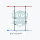 Series and Parallel LEDsConnect three LEDs in two different ways and see the difference on the same breadboard. Two LEDs are wired in series and share a single resistor; the third LED sits in parallel with them, with its own resistor. You test for yourself, by pulling one LED out, that in the series branch the current stays the same and the voltage is shared, and that in the parallel branch each LED works independently.Boshlang‘ich
- 4
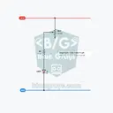 Dim an LED with a PotentiometerSet the brightness of an LED by turning a shaft. A potentiometer is an adjustable resistor: as you turn the shaft its resistance changes between 0 and 10 kΩ, and the current through the LED changes with it. By building it, you learn why a fixed resistor is always added next to the pot and which two of the three legs are used.Boshlang‘ich
- 5
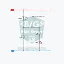 Voltage Divider: Brightness with an LDRYour first circuit that measures light. An LDR is a sensor whose resistance falls as more light lands on it. When you connect it one after the other with a fixed resistor, you get a voltage divider: the voltage in the middle rises with the light and drives the LED. When you cover the sensor with your hand the LED goes out; when you shine a flashlight on it the LED gets bright. Here you learn the divider formula at the heart of sensor circuits.Boshlang‘ich
- 6
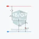 Capacitor: Slow-Fading LEDWhen you release the button, the LED should not go out at once but fade slowly over a few seconds. The part that makes this happen is the capacitor: it charges while the button is pressed and, when you release it, gives the energy it has stored back to the LED. You see with your own eyes how 1000 µF and 1 kΩ set the fade time, why an electrolytic capacitor has a polarity and what the RC time constant is.Boshlang‘ich
- 7
 Diode: One-Way PathA one-way path for current: a diode lets current pass in only one direction and blocks it in the reverse direction. Add a 1N4007 to your circuit and see the LED light; then turn the diode around and watch the LED go out. You learn to account for the 0.7 V that drops across the diode and the reverse polarity protection that protects the circuit when the battery is connected backwards.Boshlang‘ich
- 8
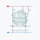 AND, OR with ButtonsBuild logic gates without an IC, using only push buttons. When two buttons are wired in series, the LED lights only when both are pressed together: this is the AND gate. When two buttons are wired in parallel, either one is enough: this is the OR gate. You build the two circuits side by side on the same breadboard and fill in the truth table with your own fingers.Boshlang‘ich
- 9
 Two-Way Switch: One Light from Two PlacesThe secret of turning off at the top of the stairs the light you turned on at the bottom: two-way switch wiring (three-way in the US). Control a single LED from two separate places with two slide switches and the two traveler wires between them. You see that the switch steers the current to one of two paths instead of cutting it, and that the logic equivalent of this circuit is EXCLUSIVE OR.Boshlang‘ich
- 10
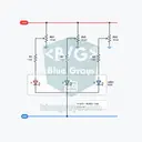 Color Mixing with an RGB LEDProduce any color you want with a single LED. Inside an RGB LED there are three separate LEDs, red, green and blue; you mix colors by turning each one up and down with its own potentiometer. Red and green make yellow, red and blue make purple. You learn the common cathode connection, why each color needs its own resistor and how screens create colors.Boshlang‘ich
Qiyinlik darajasi bo‘yicha sxemalar
Boshlang‘ich daraja37 ta sxema
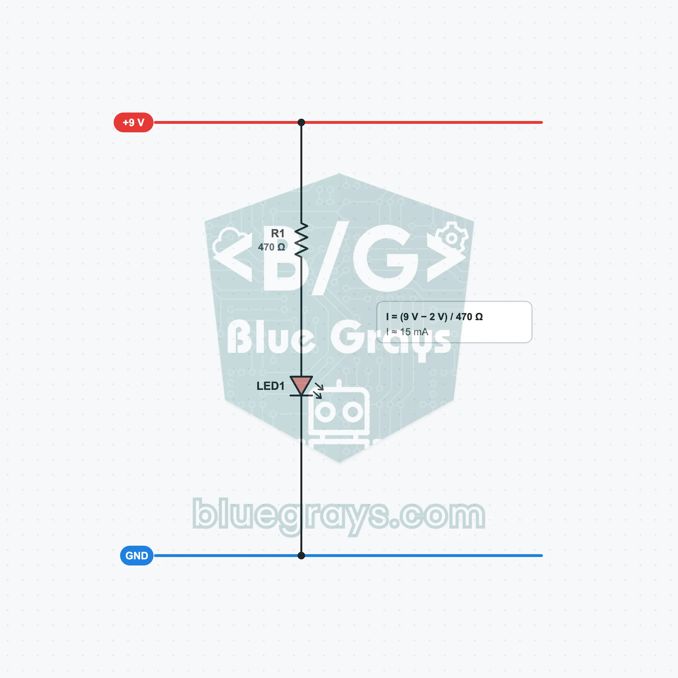
LED and Resistor: Your First Circuit
This is where electronics starts: build your first circuit with a 9 V battery, a resistor and an LED. No code, no board. On your own breadboard you see why an LED lights in only one direction, why the resistor is a must and how the 470 Ω value is calculated. Here you learn the current limiting calculation you will use in every circuit that follows.
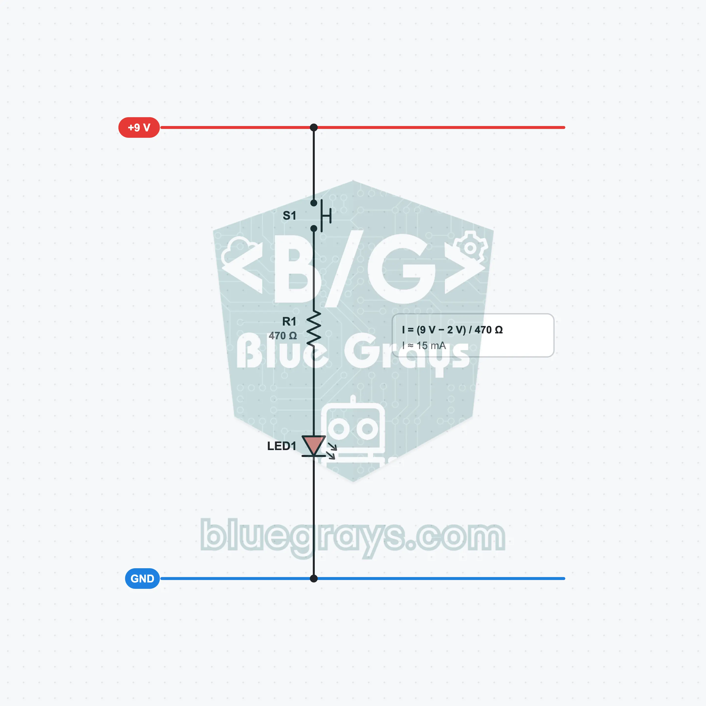
Light an LED with a Push Button
Add a push button to your first circuit: the LED lights when you press it and goes out when you release it. A button is like a bridge; pressing it completes the path, releasing it opens the path. You feel the difference between an open circuit and a closed circuit at your fingertip. You also learn which legs of a four-leg button are connected inside and how it sits on the breadboard.
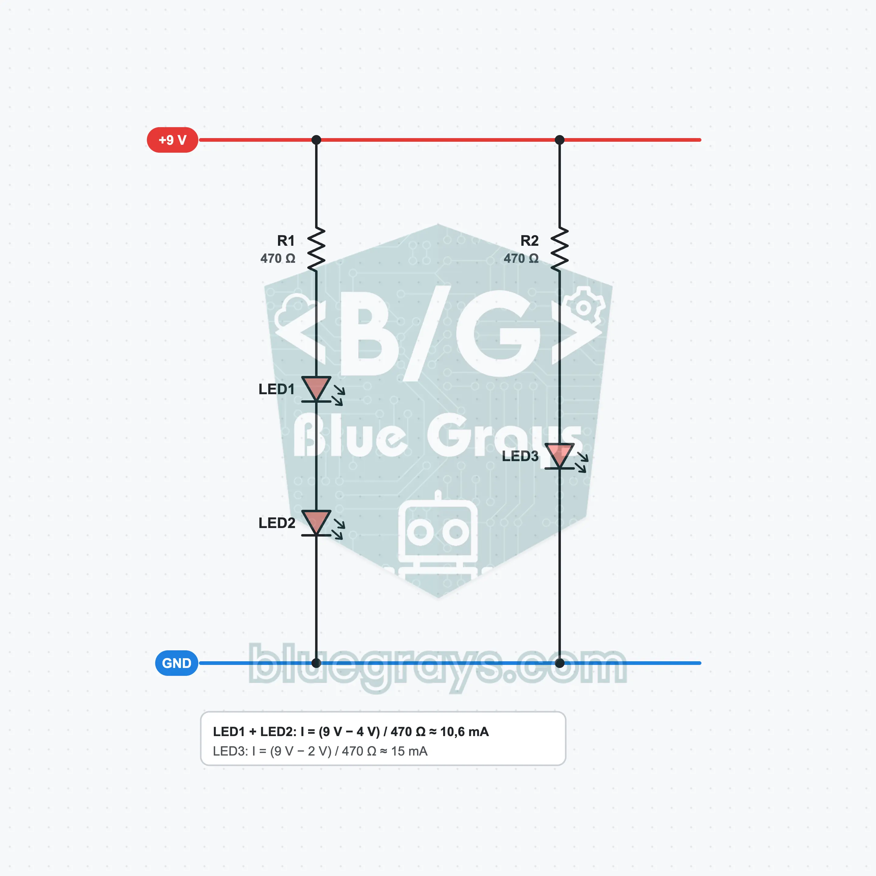
Series and Parallel LEDs
Connect three LEDs in two different ways and see the difference on the same breadboard. Two LEDs are wired in series and share a single resistor; the third LED sits in parallel with them, with its own resistor. You test for yourself, by pulling one LED out, that in the series branch the current stays the same and the voltage is shared, and that in the parallel branch each LED works independently.
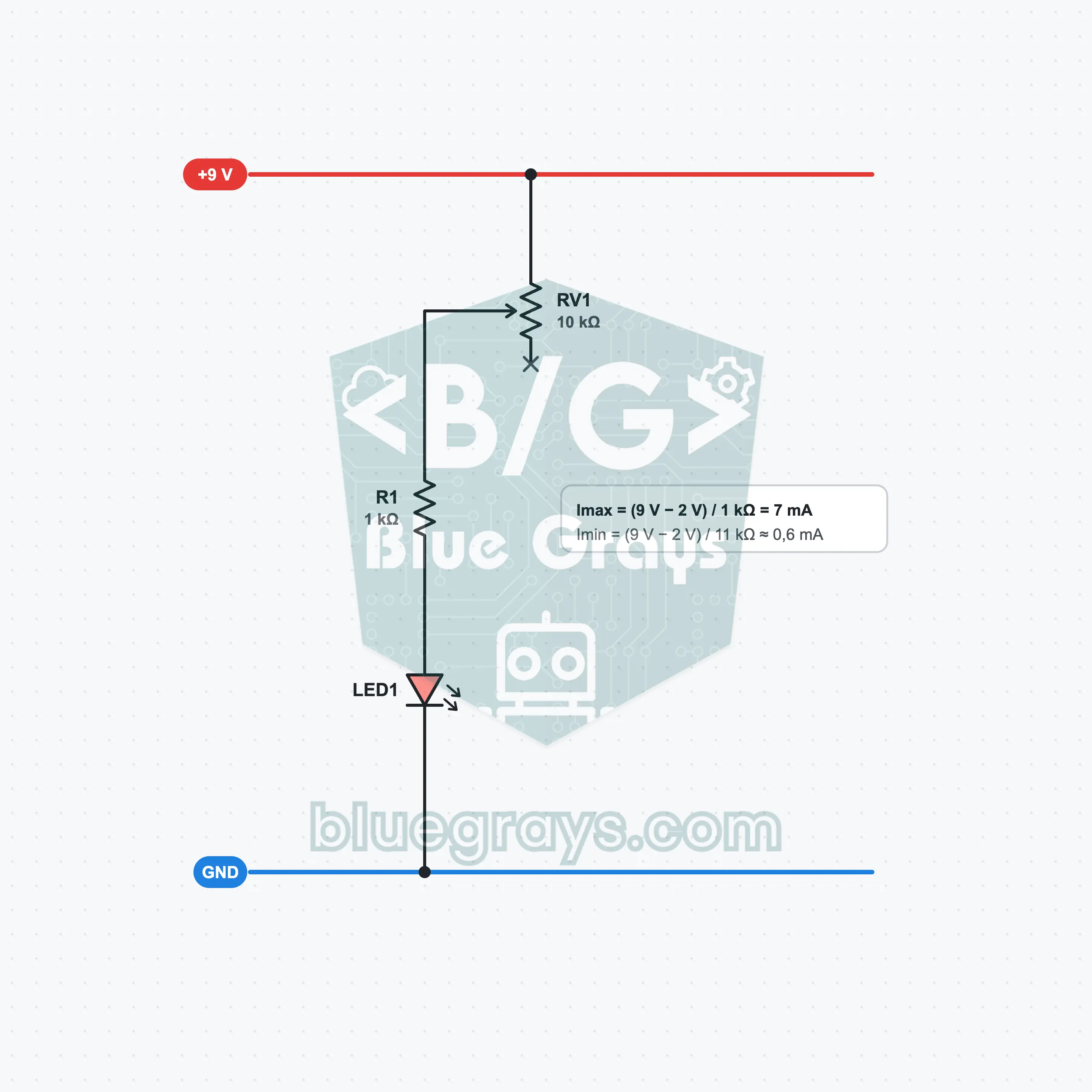
Dim an LED with a Potentiometer
Set the brightness of an LED by turning a shaft. A potentiometer is an adjustable resistor: as you turn the shaft its resistance changes between 0 and 10 kΩ, and the current through the LED changes with it. By building it, you learn why a fixed resistor is always added next to the pot and which two of the three legs are used.
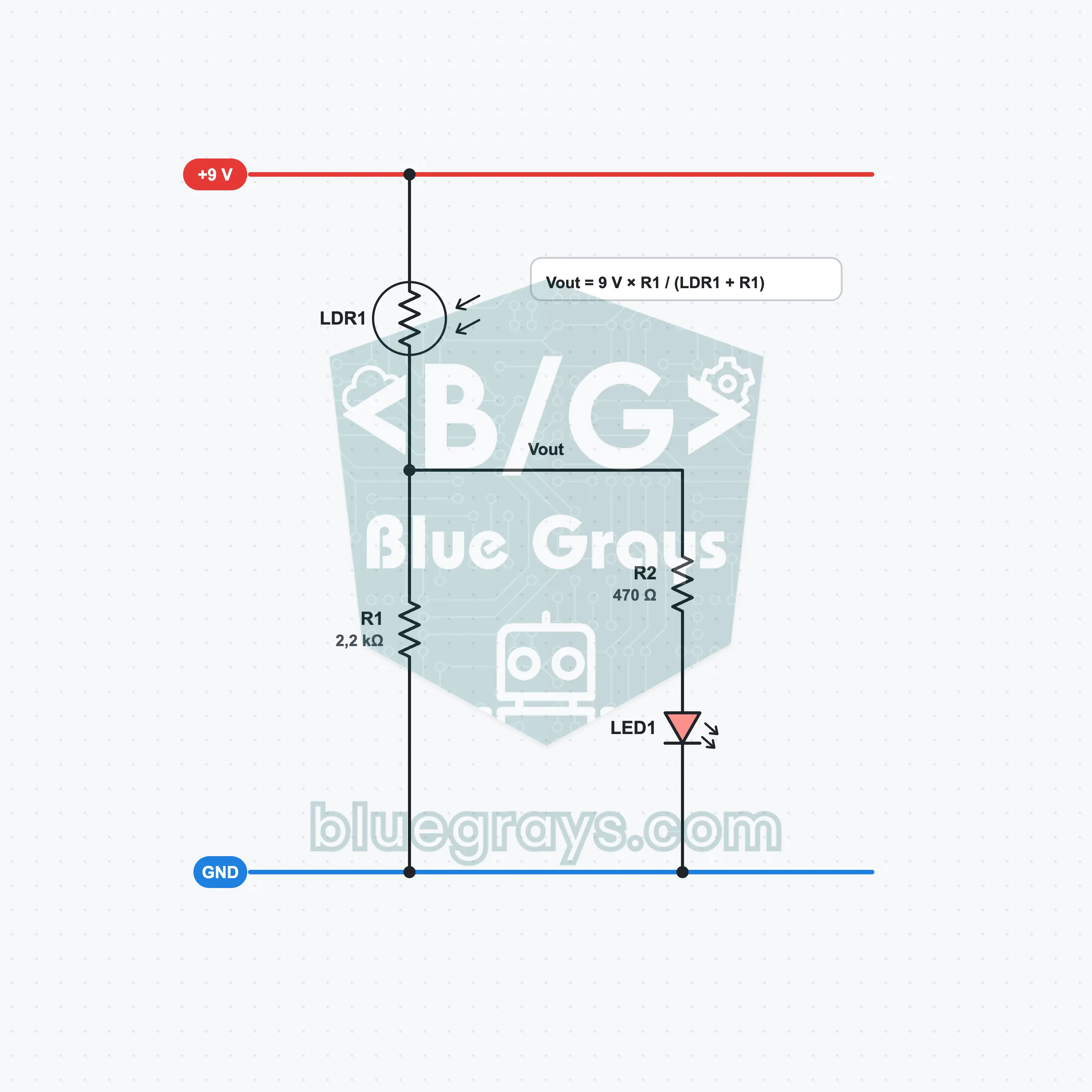
Voltage Divider: Brightness with an LDR
Your first circuit that measures light. An LDR is a sensor whose resistance falls as more light lands on it. When you connect it one after the other with a fixed resistor, you get a voltage divider: the voltage in the middle rises with the light and drives the LED. When you cover the sensor with your hand the LED goes out; when you shine a flashlight on it the LED gets bright. Here you learn the divider formula at the heart of sensor circuits.
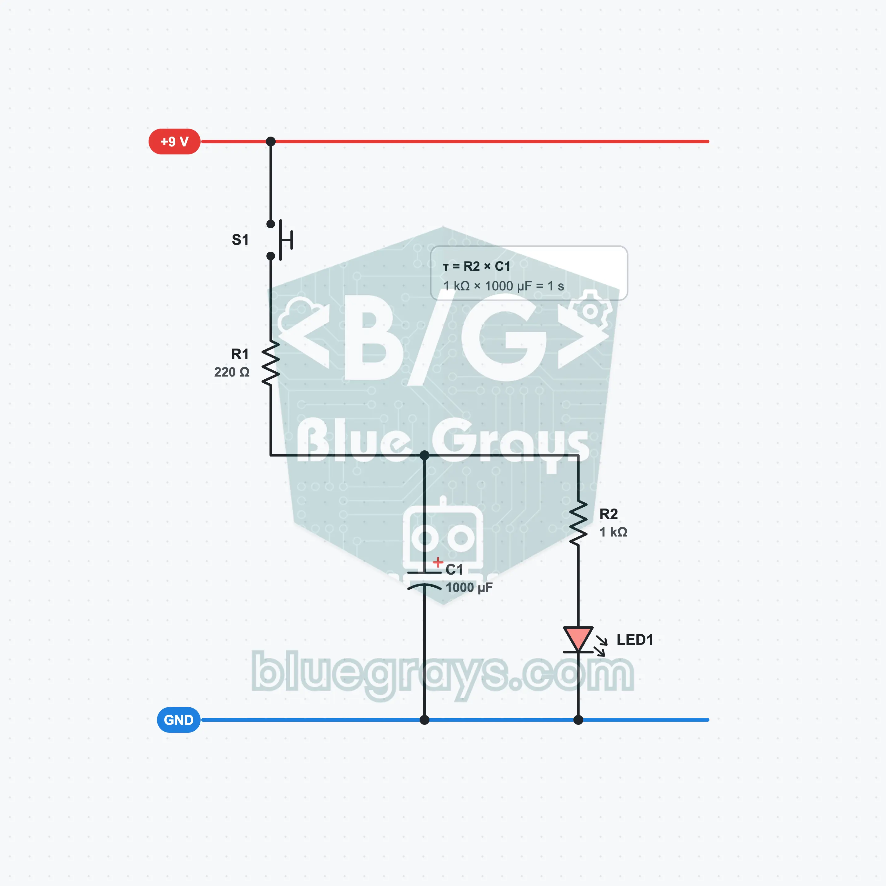
Capacitor: Slow-Fading LED
When you release the button, the LED should not go out at once but fade slowly over a few seconds. The part that makes this happen is the capacitor: it charges while the button is pressed and, when you release it, gives the energy it has stored back to the LED. You see with your own eyes how 1000 µF and 1 kΩ set the fade time, why an electrolytic capacitor has a polarity and what the RC time constant is.
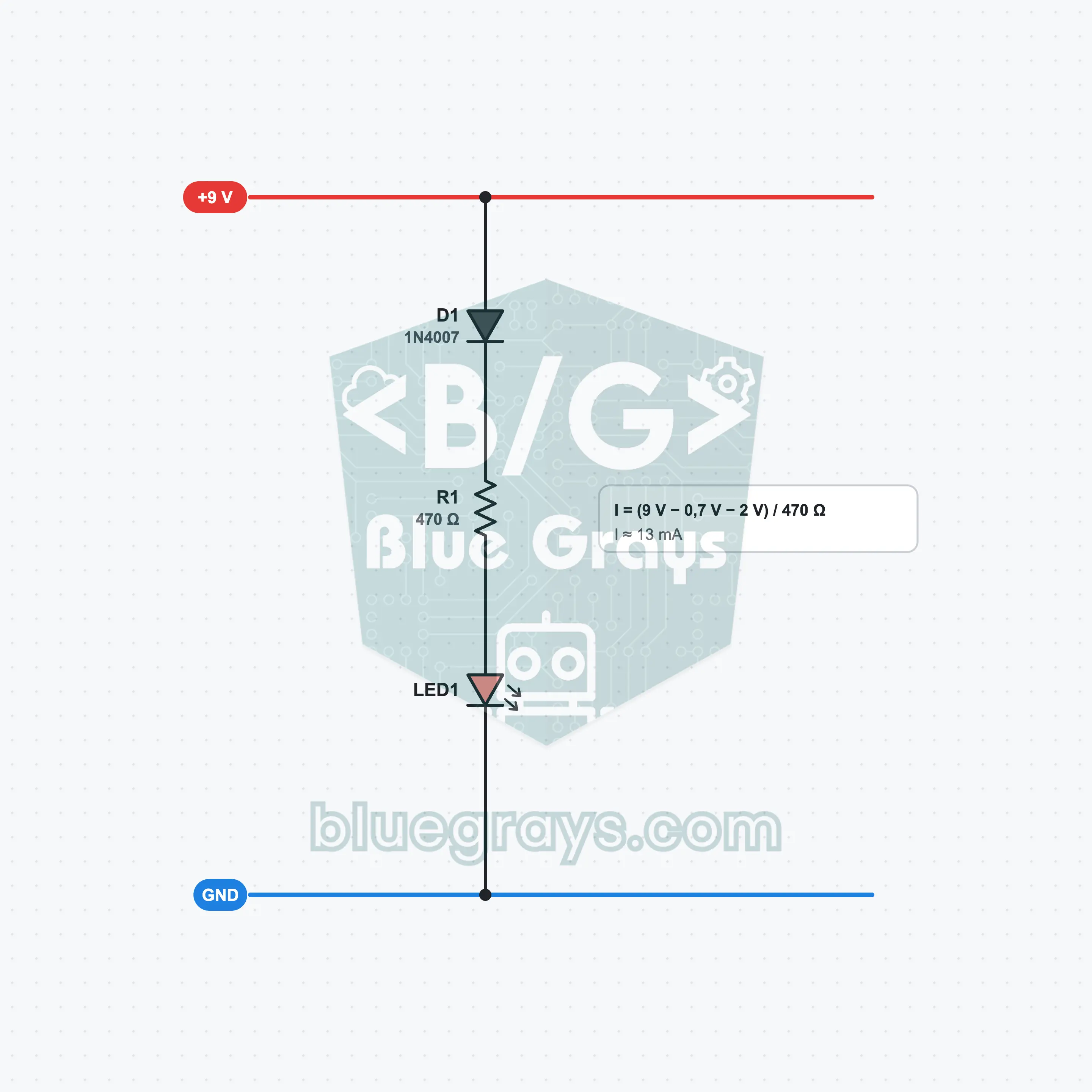
Diode: One-Way Path
A one-way path for current: a diode lets current pass in only one direction and blocks it in the reverse direction. Add a 1N4007 to your circuit and see the LED light; then turn the diode around and watch the LED go out. You learn to account for the 0.7 V that drops across the diode and the reverse polarity protection that protects the circuit when the battery is connected backwards.
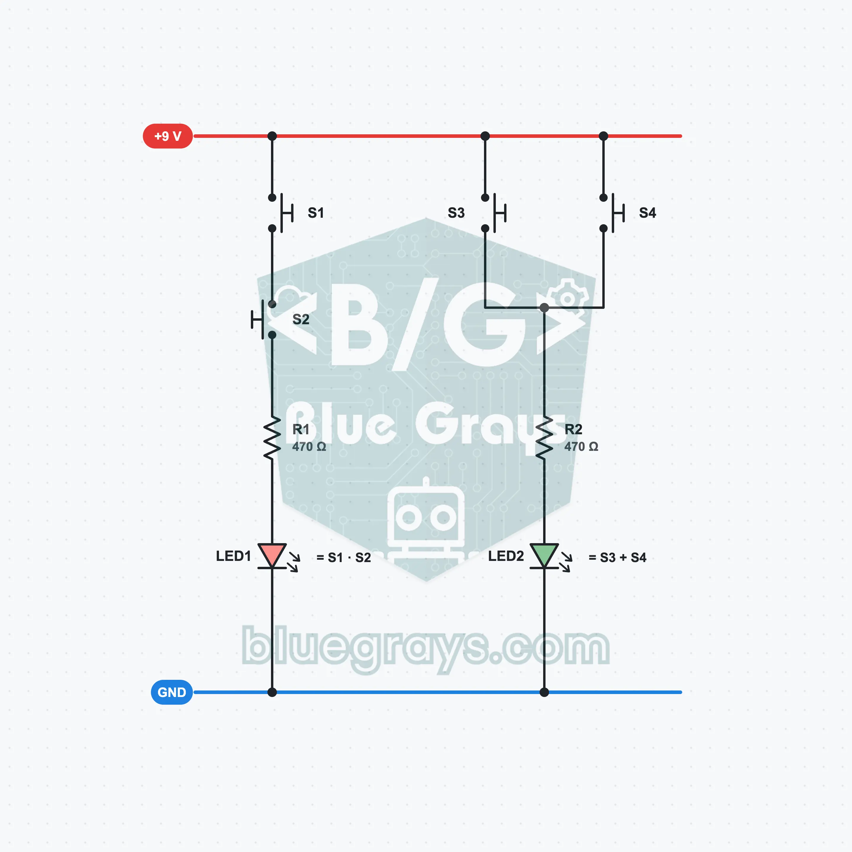
AND, OR with Buttons
Build logic gates without an IC, using only push buttons. When two buttons are wired in series, the LED lights only when both are pressed together: this is the AND gate. When two buttons are wired in parallel, either one is enough: this is the OR gate. You build the two circuits side by side on the same breadboard and fill in the truth table with your own fingers.
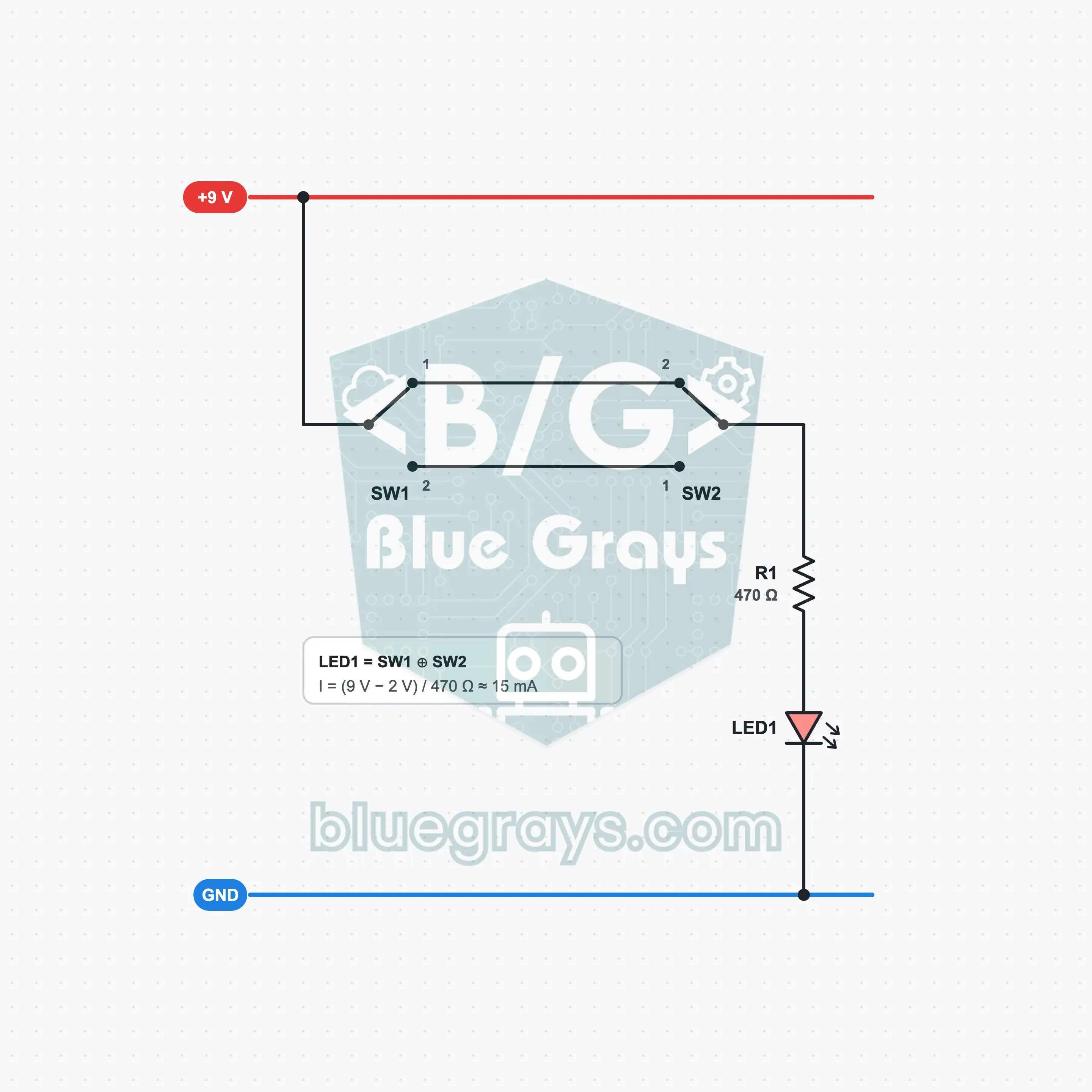
Two-Way Switch: One Light from Two Places
The secret of turning off at the top of the stairs the light you turned on at the bottom: two-way switch wiring (three-way in the US). Control a single LED from two separate places with two slide switches and the two traveler wires between them. You see that the switch steers the current to one of two paths instead of cutting it, and that the logic equivalent of this circuit is EXCLUSIVE OR.
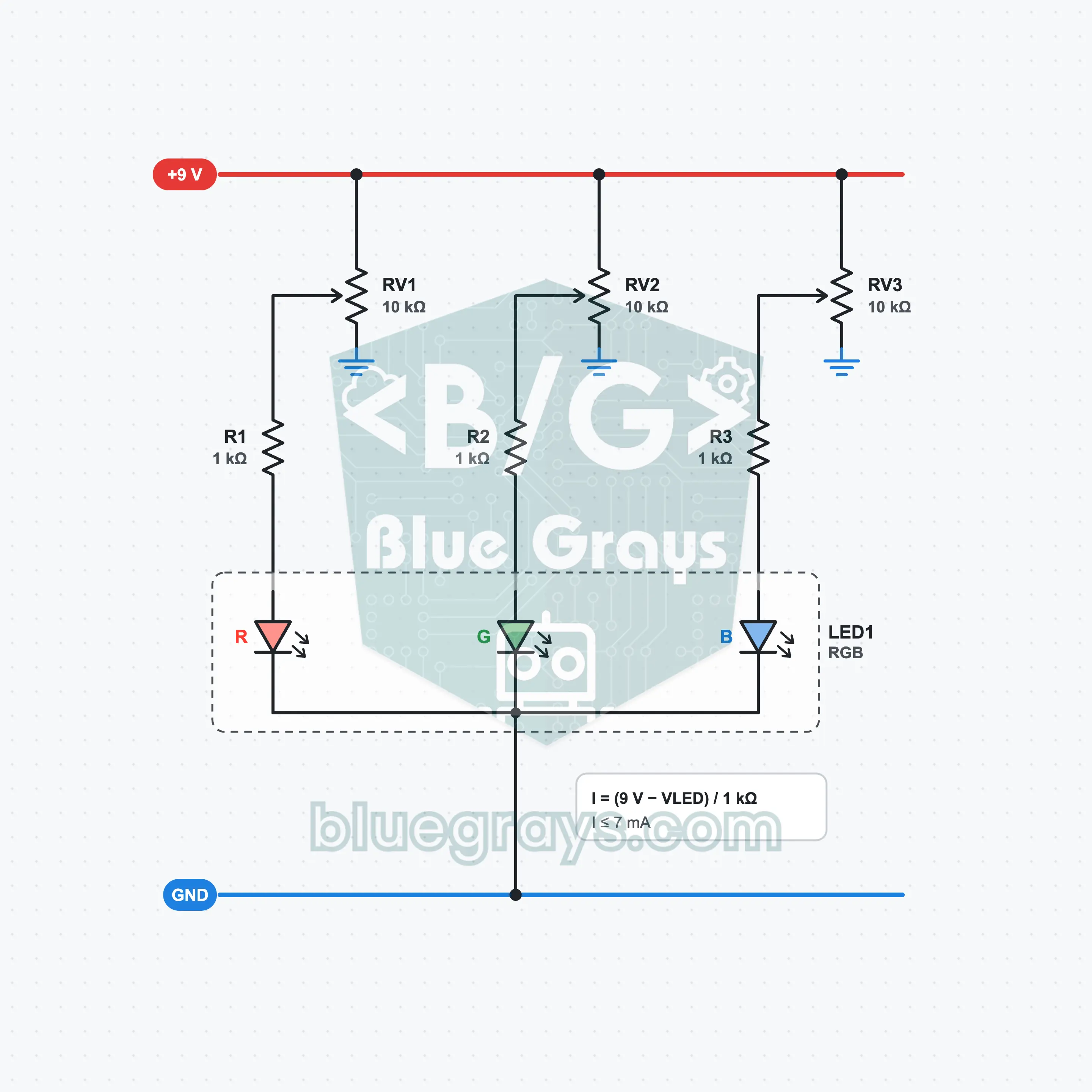
Color Mixing with an RGB LED
Produce any color you want with a single LED. Inside an RGB LED there are three separate LEDs, red, green and blue; you mix colors by turning each one up and down with its own potentiometer. Red and green make yellow, red and blue make purple. You learn the common cathode connection, why each color needs its own resistor and how screens create colors.
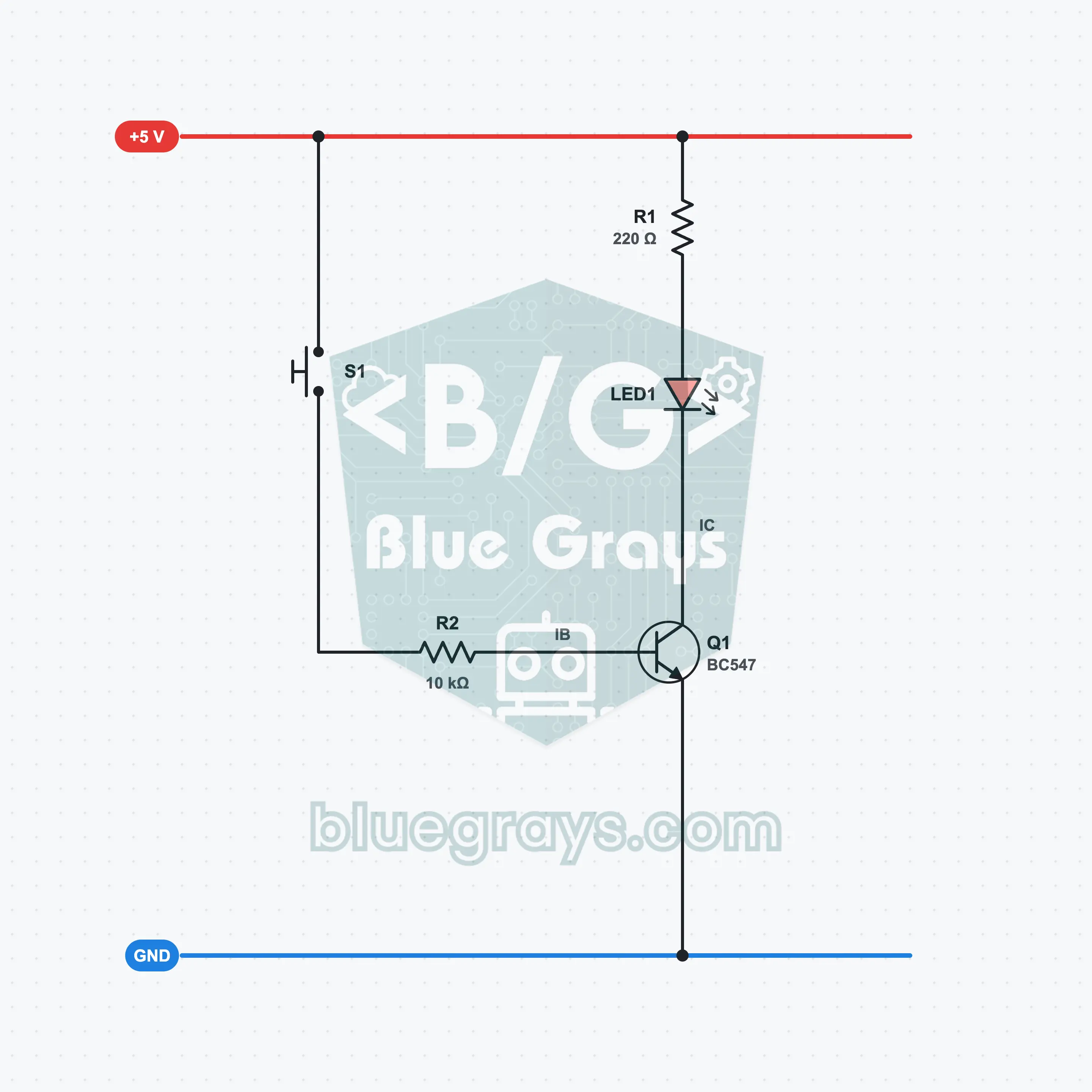
Transistor as a Switch: Lighting an LED with a Small Current
A transistor is an electronic switch that turns a large current on and off with a small one. In this circuit only 0.43 mA passes through the button; the BC547 takes this small base current and carries the LED's 13 mA through itself. When you press the button the LED lights, when you release it the LED goes out. Relay, motor and sensor circuits all start from this idea: you drive the base, the transistor carries the load.
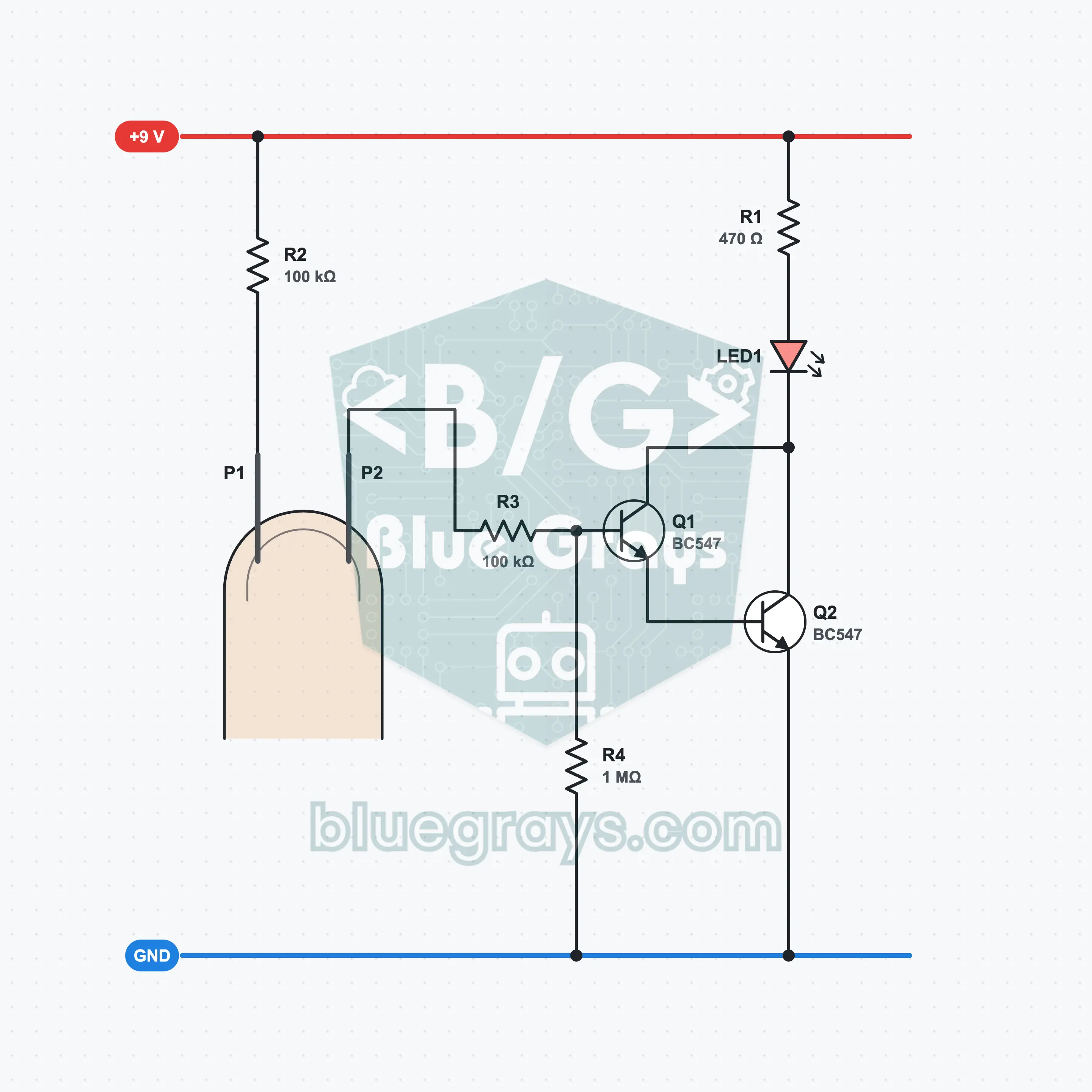
Touch Switch: A Finger-Activated LED with a Darlington Pair
A switch with no button: touch two bare wire ends with your finger and the LED lights; take your finger away and it goes out. Your finger acts like a resistor of a few megohms, passing only a few microamps. Two BC547s connected as a Darlington pair amplify this current at least 12,000 times and light the LED. You use your own finger to see what gain means and how skin conducts electricity.
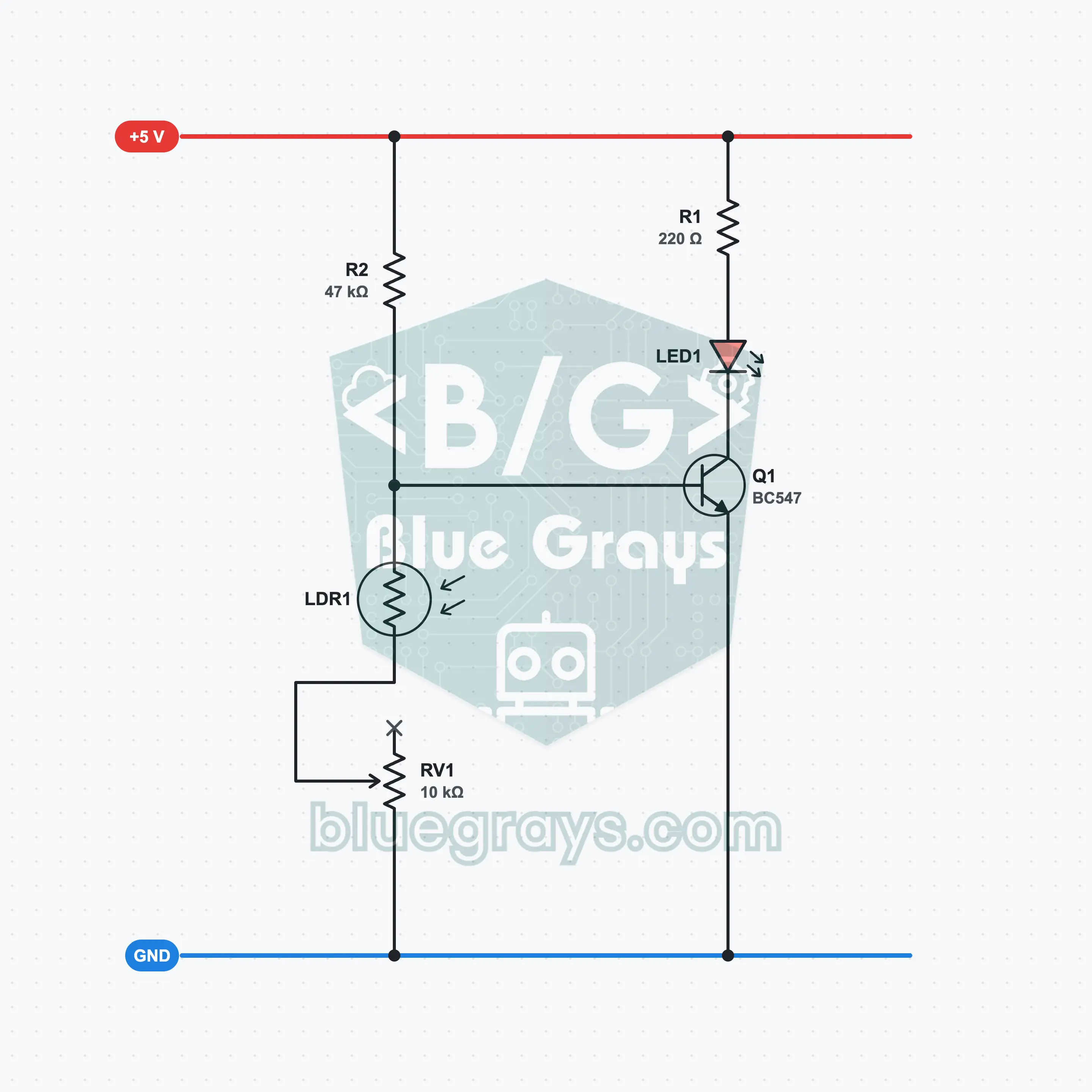
LED That Lights in the Dark: LDR and Transistor Night Light
A night light that turns on by itself when it gets dark. An LDR and a resistor form a voltage divider; as the room gets darker, the voltage at the middle of the divider rises and the BC547 transistor lights the LED. With the potentiometer you set how dark it has to be before the LED lights. You see how a transistor turns a weak signal from a sensor into something useful; the photocell in street lights works on the same idea.
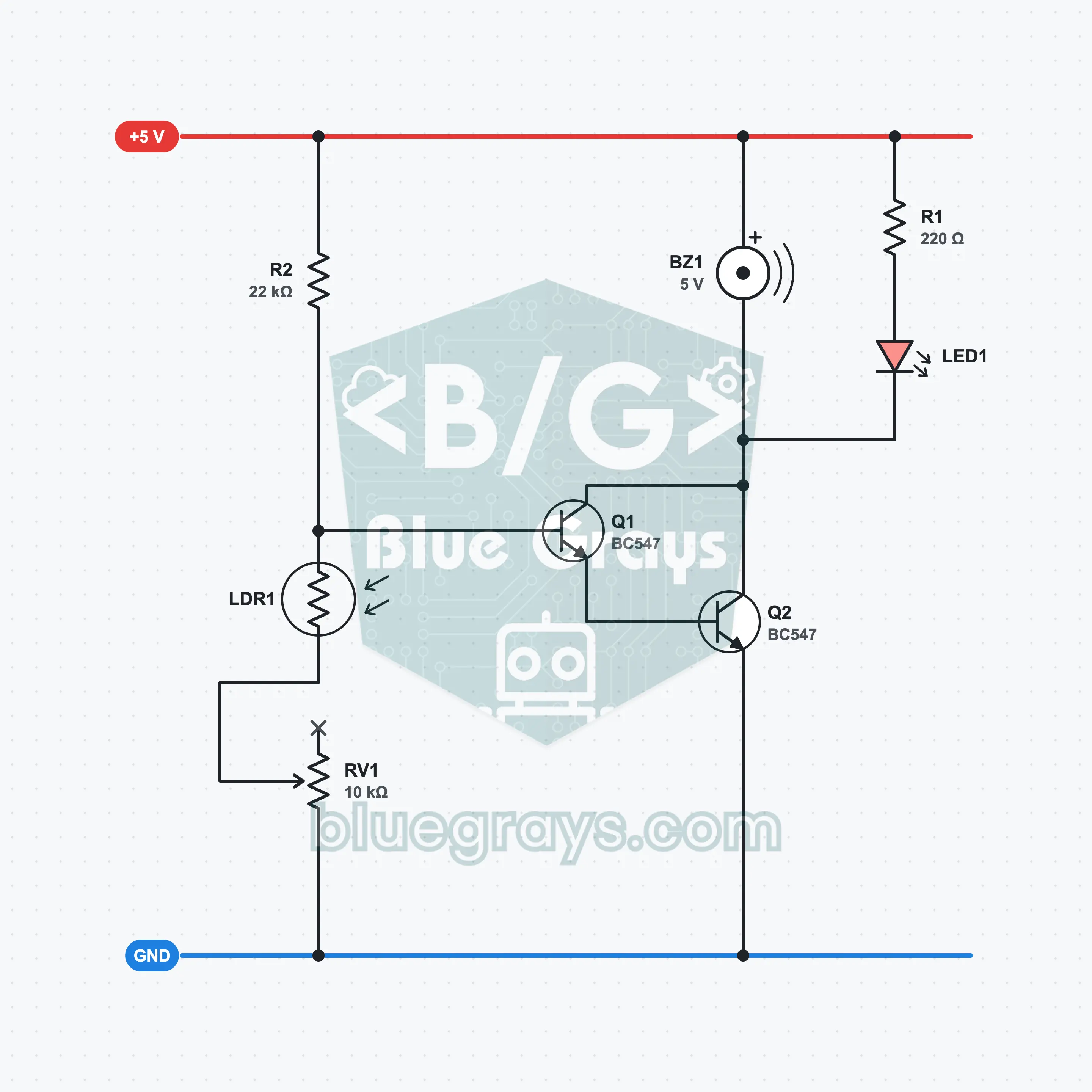
Broken-Beam Alarm: A Light Barrier with an LDR and Buzzer
An alarm that sounds when light is blocked. While the LDR receives light, it stays silent; when a hand or object blocks the light, the active buzzer sounds and the LED lights. The LDR and a resistor form a voltage divider; two BC547s in a Darlington pair drive the buzzer. You set the triggering shadow level with the potentiometer. No laser needed: room light or a phone flashlight is enough. Try the principle of doorway light barriers on your desk.
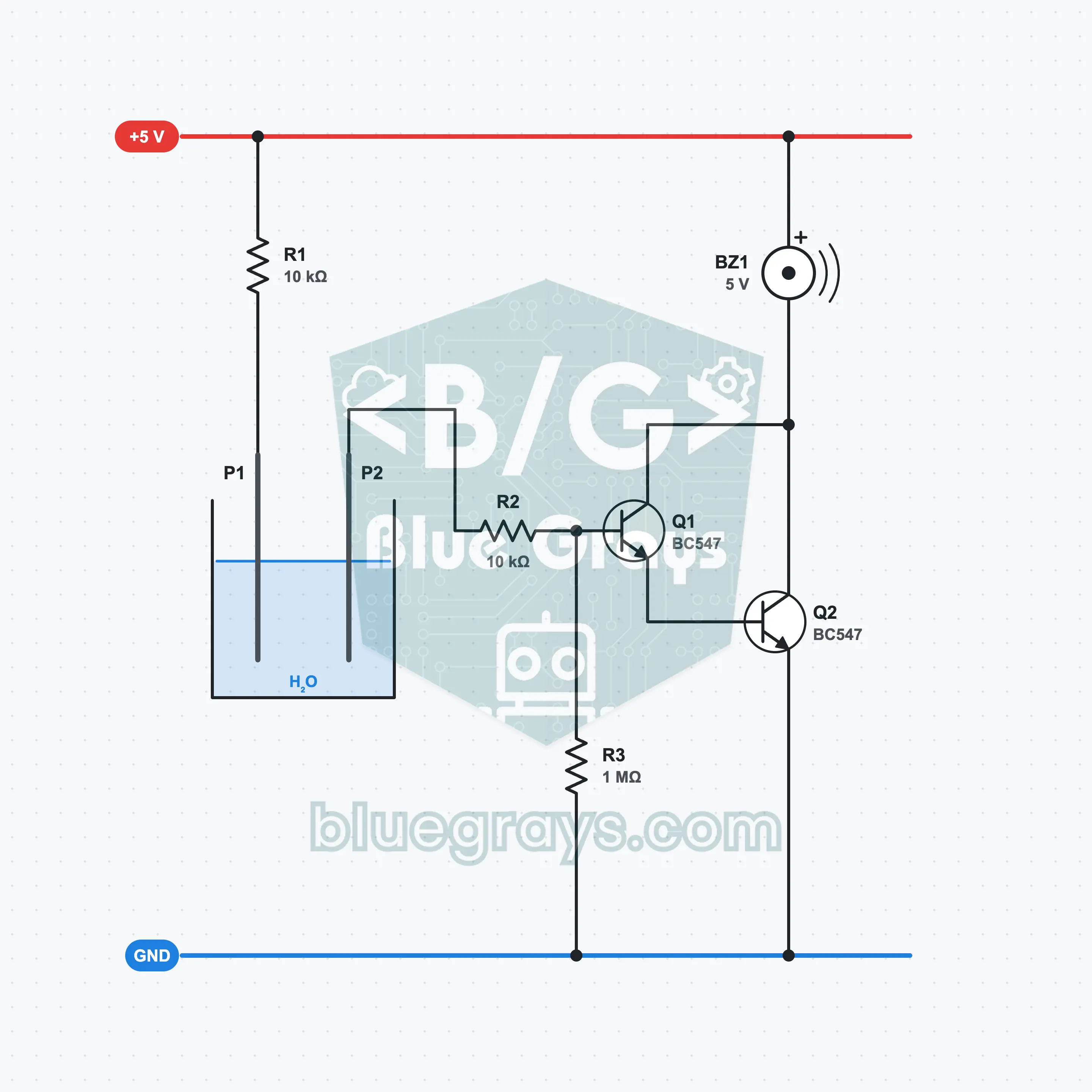
Water Level Alarm: Two-Transistor Water Detector
An alarm that sounds when the water rises. When two bare wire ends touch water, the water passes a very weak current between them. This current cannot run a buzzer by itself; two BC547s connected as a Darlington pair amplify it thousands of times and the active buzzer sounds. This is the basis of circuits that warn you before the bathtub overflows or a plant saucer fills up. You try out the conductivity of water and how the gains of two transistors multiply.
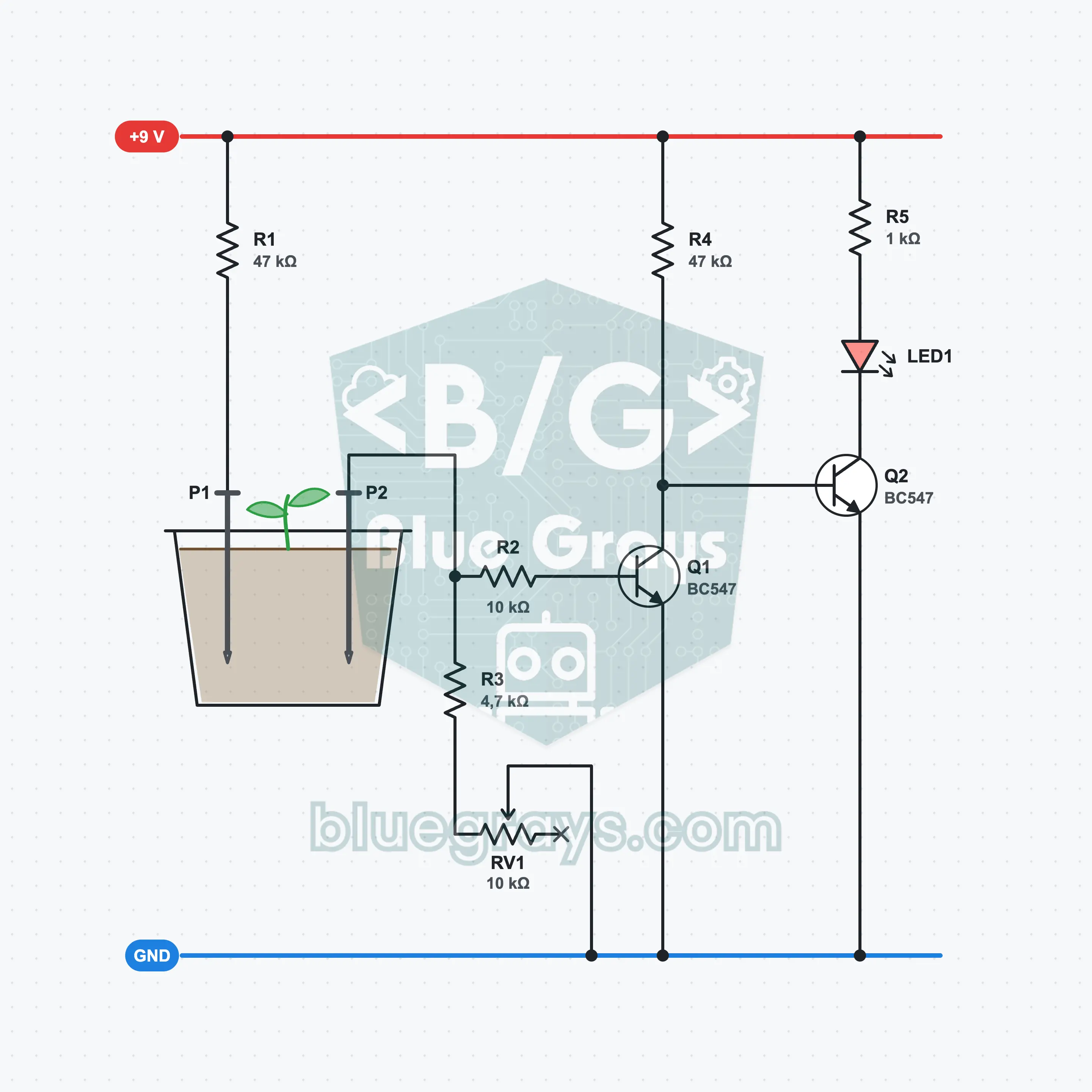
Thirsty Plant Indicator: An LED That Lights When the Soil Dries Out
A soil moisture indicator that lights an LED when the soil in the pot dries out, telling you it is time to water. Two nails are pushed into the soil: wet soil passes current easily, dry soil barely does. A two-stage switch built with two BC547s inverts the signal; while the soil is wet the LED stays off, and when it dries out the LED lights. You set the threshold for your own soil with the RV1 pot. You try out the conductivity of soil, inverting with a transistor and electrolysis.
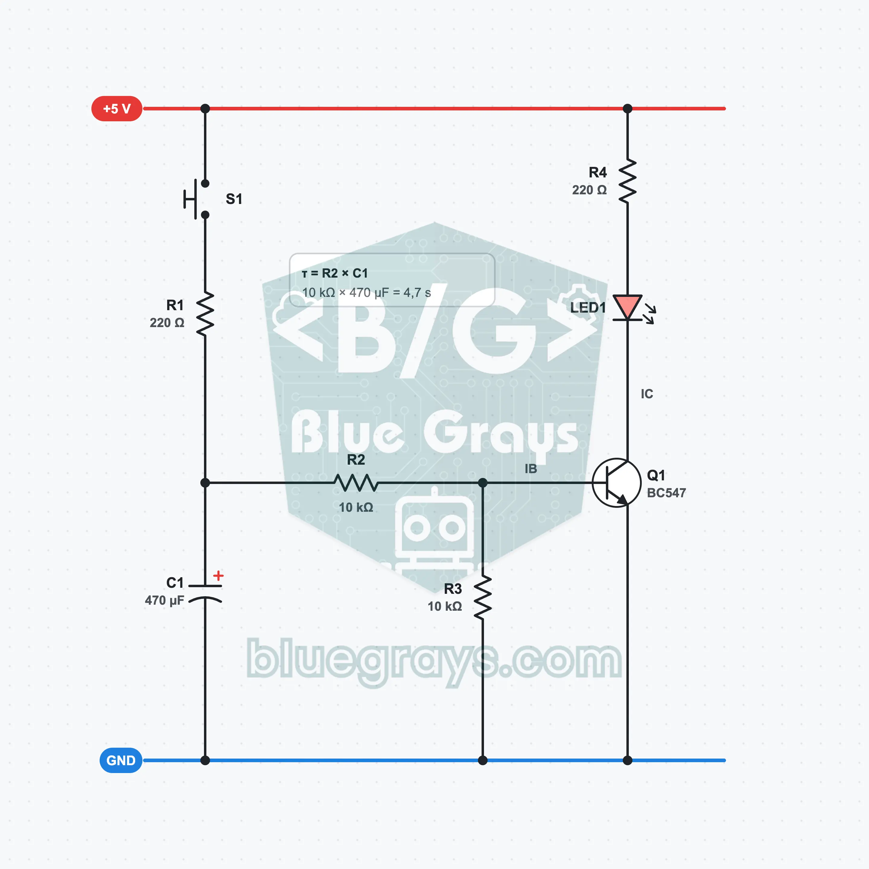
Delayed-Off Light: Transistor Staircase Timer
Press and release the button: the LED stays at full brightness for a few seconds, then fades. This is the idea behind a staircase timer in an apartment building. The 470 µF capacitor charges while you hold the button; on release, it supplies a small base current to the BC547, keeping it on. Since the supply provides the LED current, this capacitor keeps the light on for about 10 seconds. See the RC time constant and base current in your own circuit.
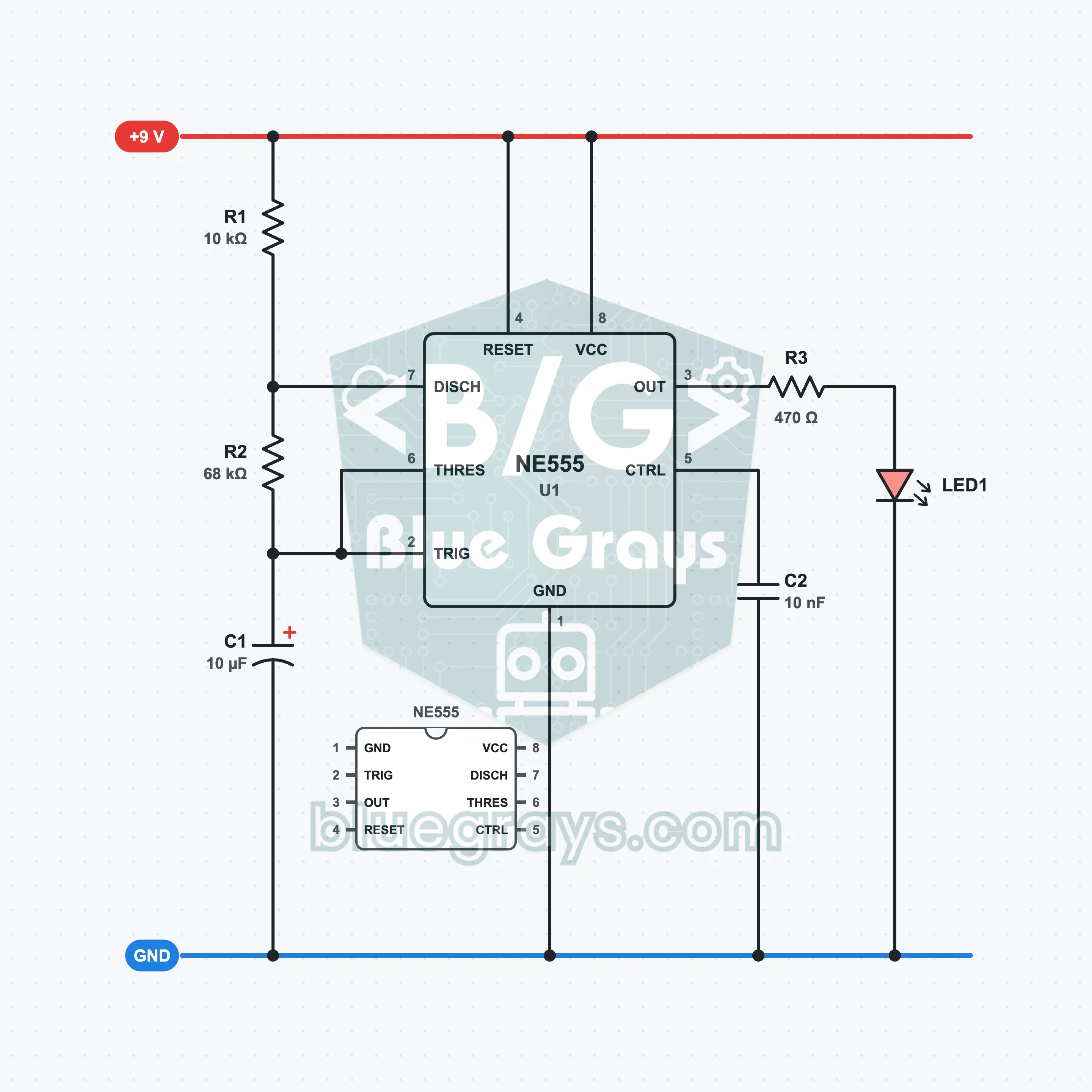
555 Flasher: Blinking LED Circuit
No code, no board: with a single NE555 IC, three resistors and two capacitors, make an LED flash about once a second. This circuit is the 555's astable mode, that is, its free-running mode. You see the capacitor charging and discharging, the 1/3 and 2/3 thresholds and the frequency formula in a circuit you built yourself. You also try out how the speed changes when you swap the resistor or the capacitor.
Adjustable-Speed Flasher: 555 Circuit with a Potentiometer
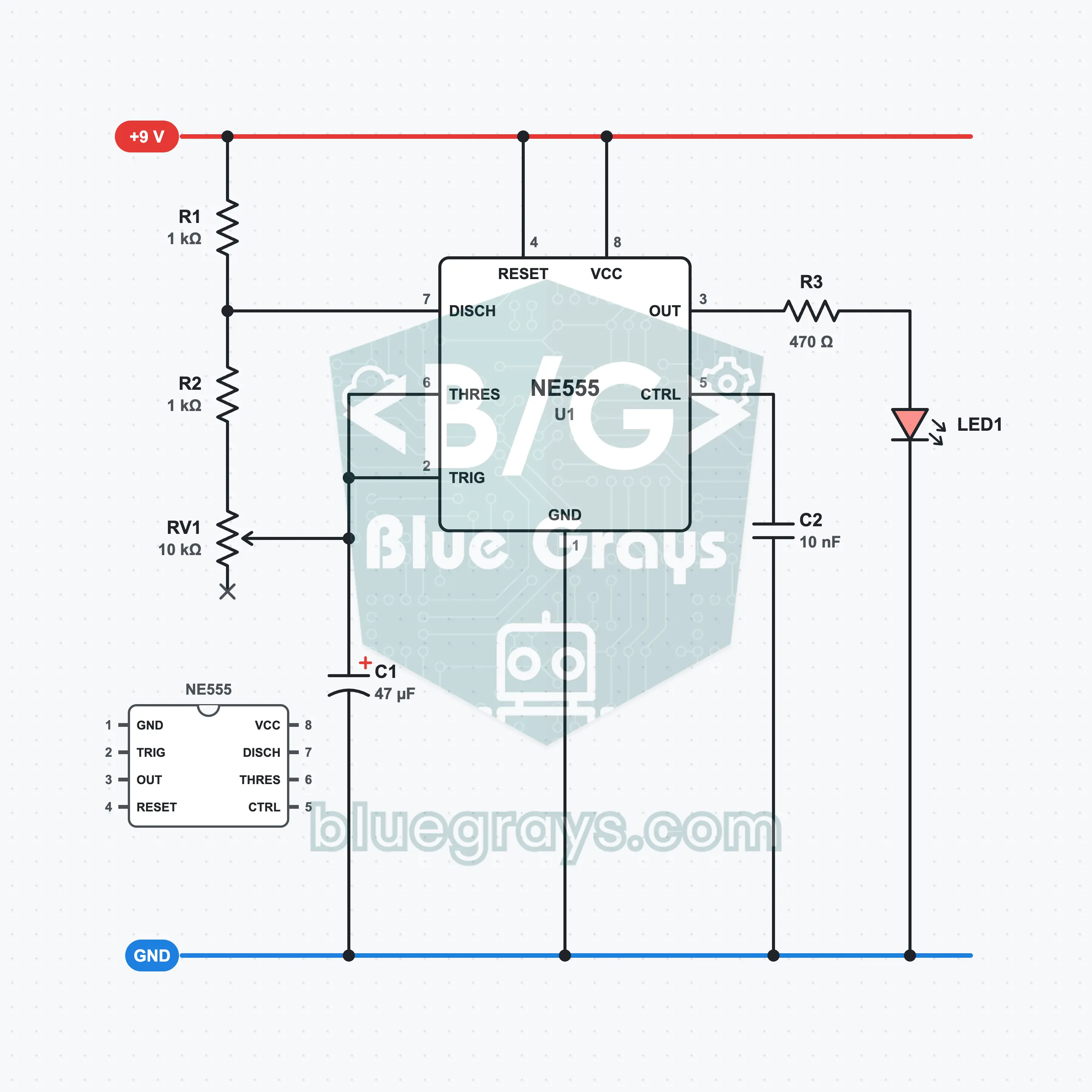
Replace the fixed resistor in the 555 Flasher circuit with a potentiometer to adjust the LED's flashing speed by hand. At one end, it flashes about 1.3 times a second; at the other, about 10 times. Learn how to wire the pot as an adjustable resistor, what the frequency formula gives at both ends and how the fixed 1 kΩ resistor in series with the pot protects the 555.
Two LEDs Lighting in Turn: Source and Sink with the 555 Output
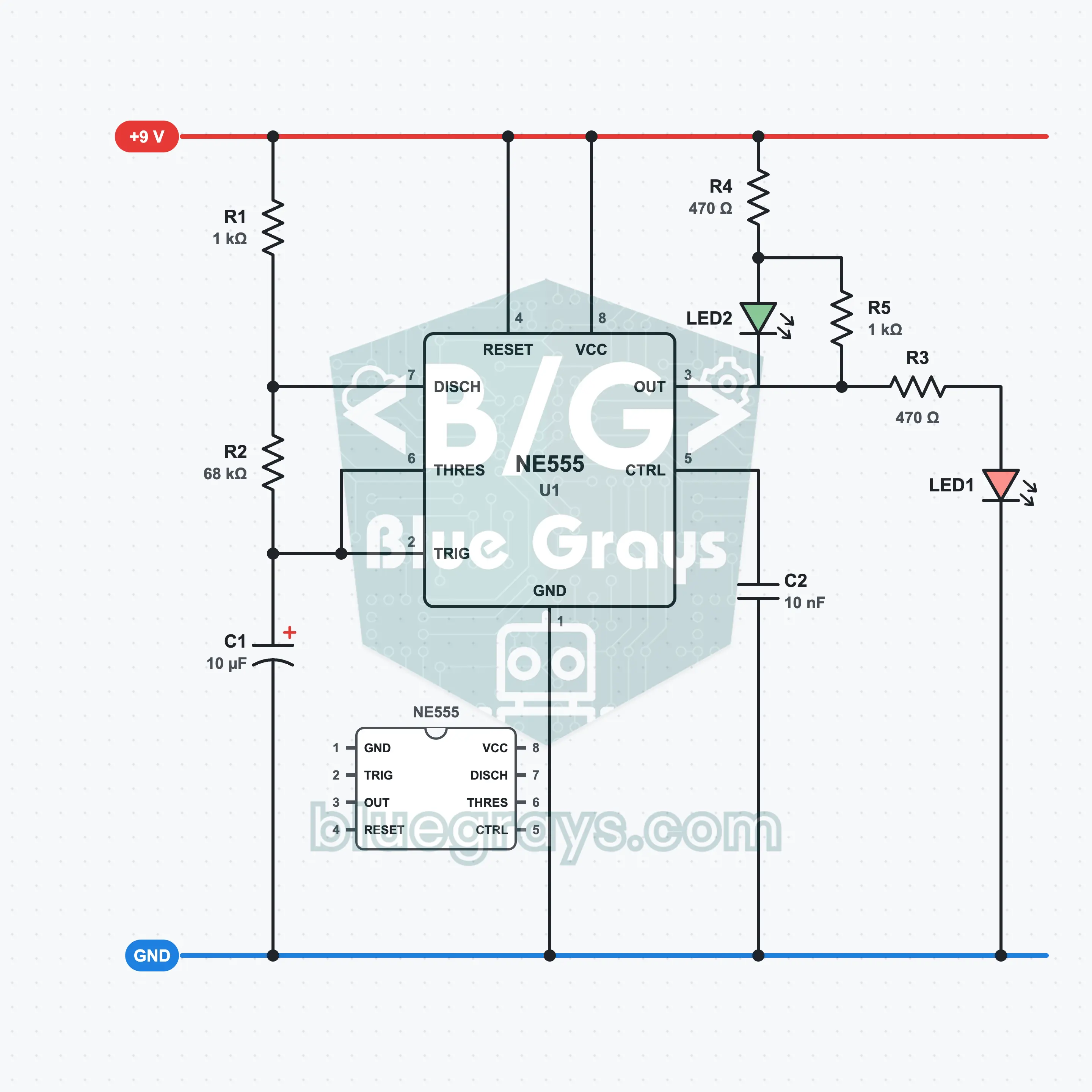
A red and a green LED light in turn: one lights while the other goes out, each for about half a second. A single NE555 does it all. When the output (pin 3) is high it sources current to one LED; when it is low it sinks the current coming from the other LED. A small 1 kΩ R1 makes the two times almost equal, and a resistor in parallel with LED2 stops both LEDs from glowing faintly at the same time.
555 Timer: Press the Button, Light for 5 Seconds
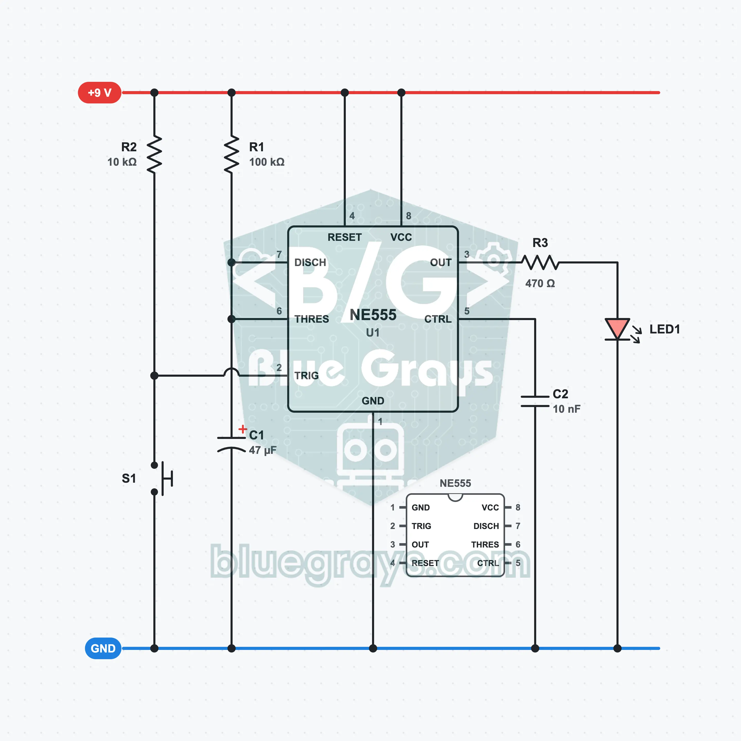
Press the button once and the LED lights for about 5 seconds, then goes out by itself. This circuit is the NE555's monostable mode, that is, its one-shot mode: the basis of staircase light timers, delayed lamps and timers. The time is set by just one resistor and one capacitor. You try out the trigger input, the threshold voltage and the formula T = 1.1 × R × C in a circuit you built yourself.
555 Flip-Flop: Two-Button Memory Circuit
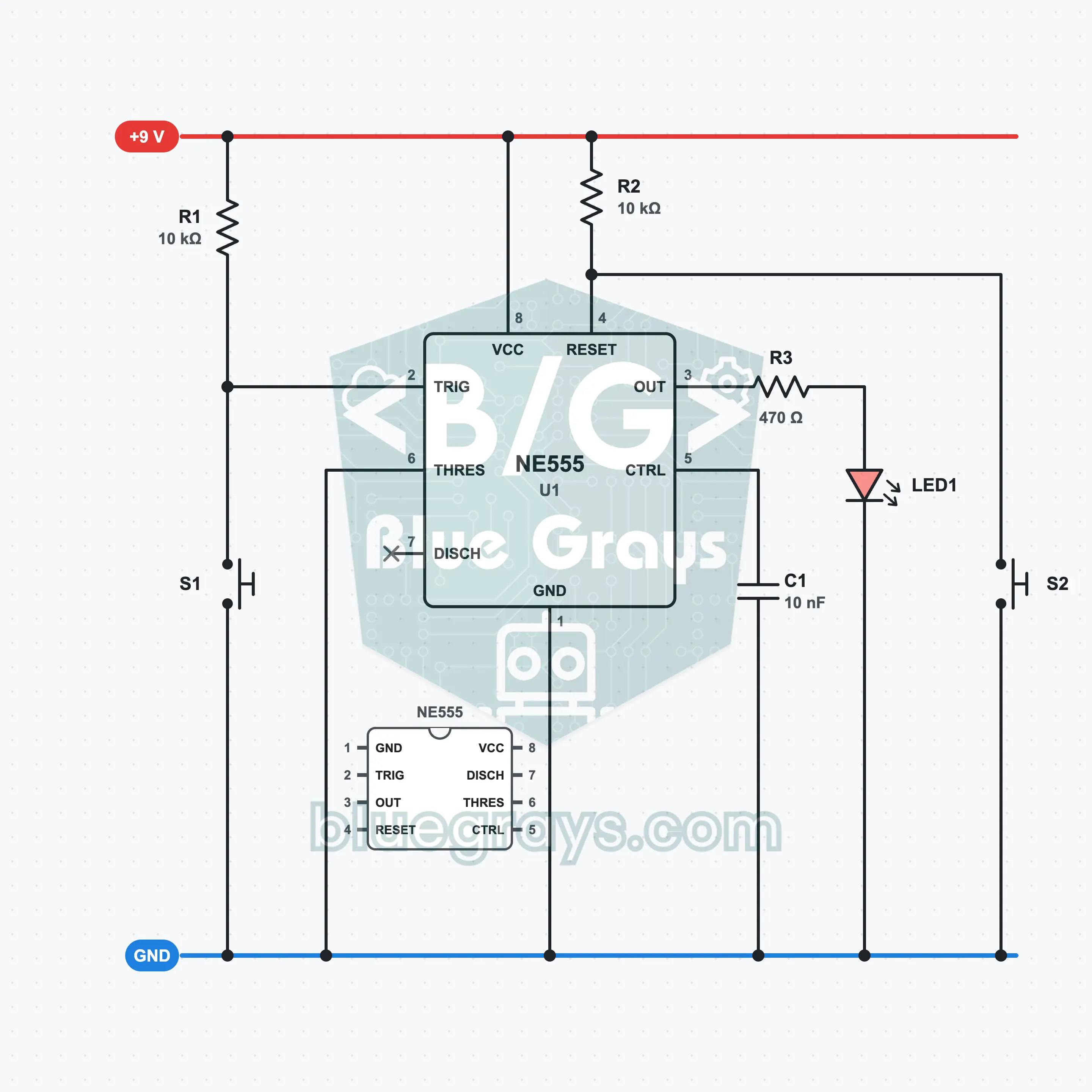
Press one button and the LED lights; take your finger off and it stays lit. Press the other button and it goes out. The bistable mode of the NE555 uses the flip-flop inside it directly: no counting time with a capacitor, only SET and RESET. This circuit is the easiest form of 1-bit memory to build and is ideal for seeing flip-flop logic for the first time.
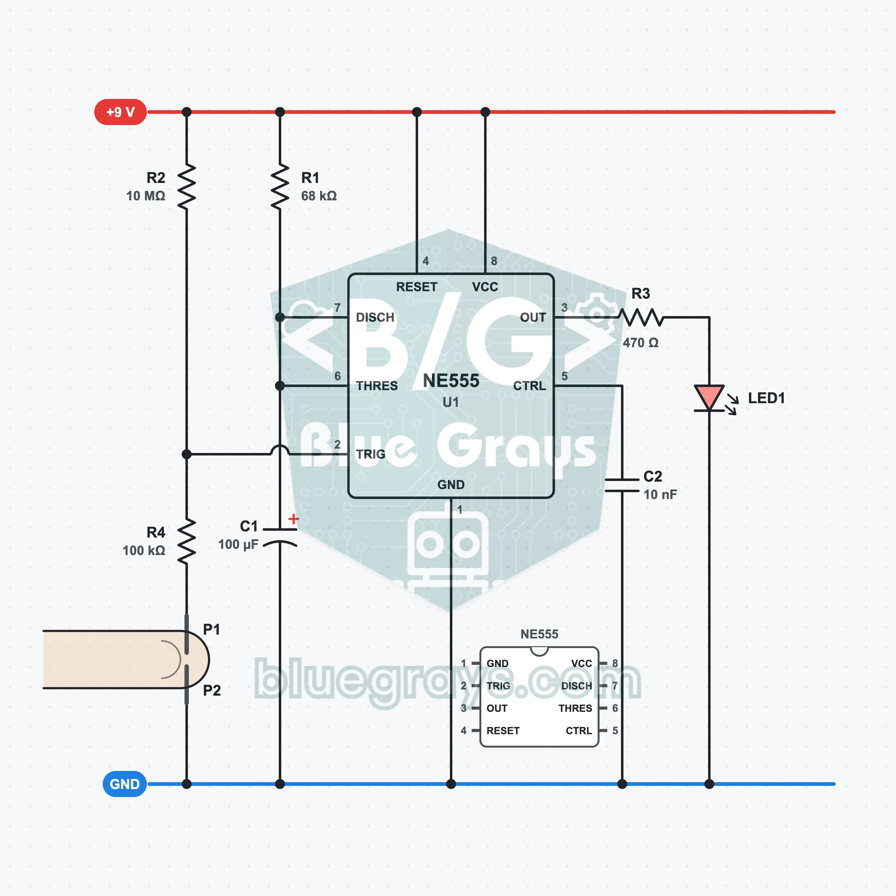
Touch Timer: A Finger-Triggered 555
Hold the two wire ends together with one finger: the LED lights and goes out by itself after about 7.5 seconds. Your finger acts like a resistor of a few megohms between the two ends and pulls the trigger input of the NE555 down. The 10 MΩ resistor that holds the input high makes even this tiny current enough. You see for yourself, with your own finger, how sensitive the trigger input is and what that sensitivity depends on.
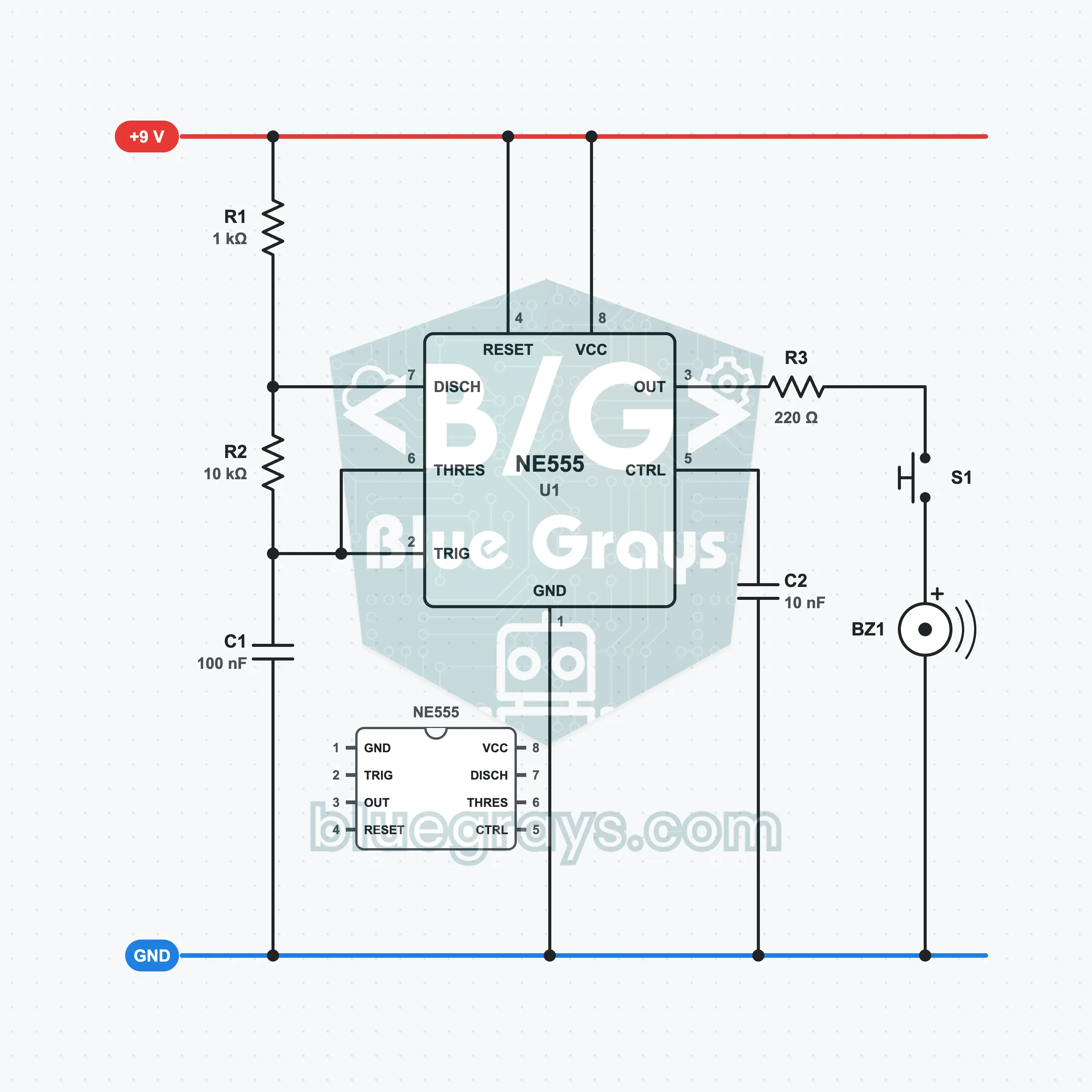
Buzzer Tone Generator: Audio Frequency with the 555
Turn an NE555 IC into a switch that opens and closes about 686 times a second, and hear the result with your own ears. When you press the button, the passive buzzer gives a high, steady tone; two resistors and a capacitor set how high or low it sounds. In a circuit you built yourself, you see what audio frequency is, the frequency formula of astable mode and why the sound gets higher when you change one resistor.
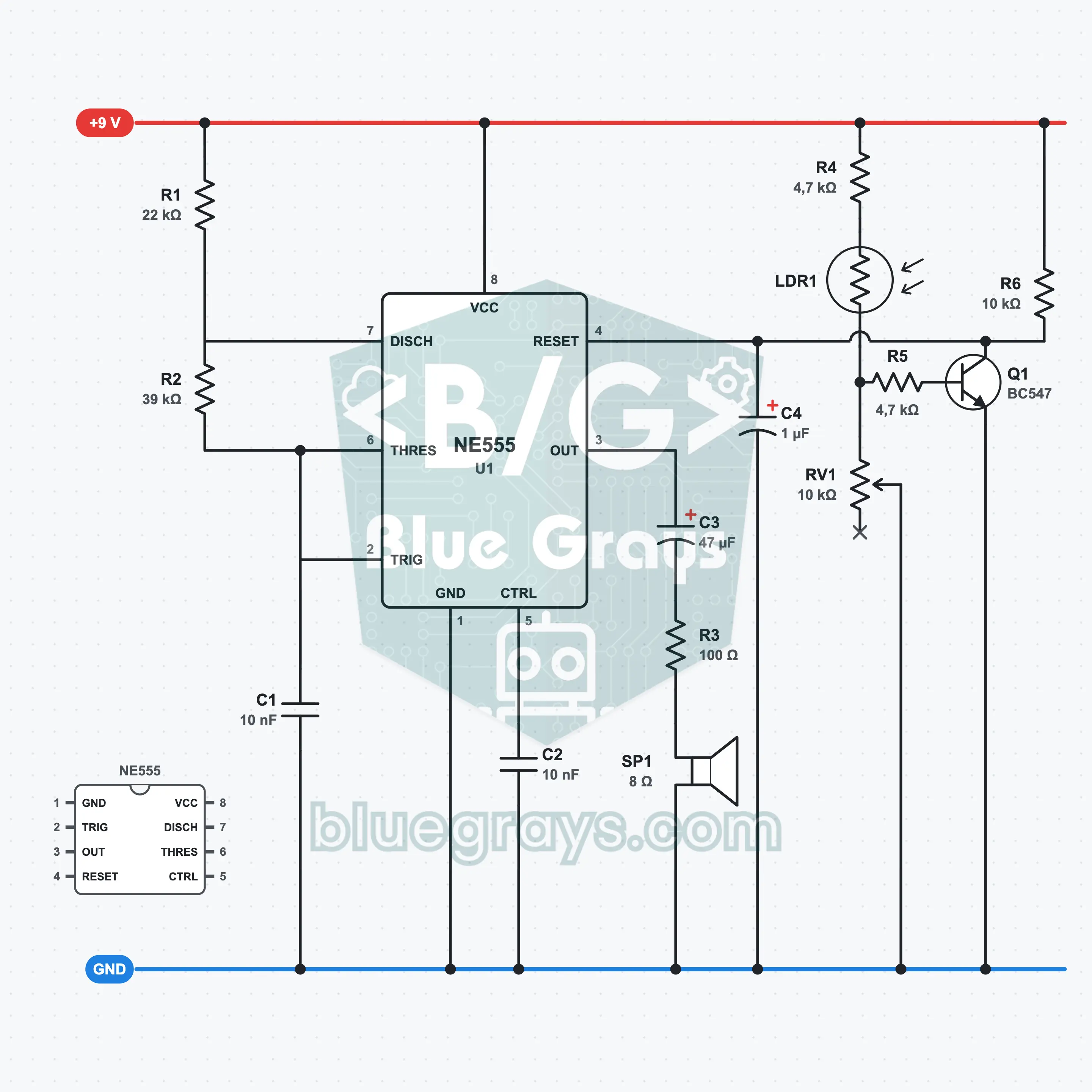
Darkness Alarm: A 555 Circuit That Sounds When the Light Goes Out
An alarm that starts sounding when the light goes out. The NE555 produces a tone of about 1.4 kHz in the speaker; a BC547 controls the RESET input (pin 4). In the light, the LDR turns the transistor on, pin 4 is pulled to GND and the 555 goes silent. In the dark, the transistor turns off and the alarm sounds. With the pot you set the threshold between about 0.2 and 45 lux.
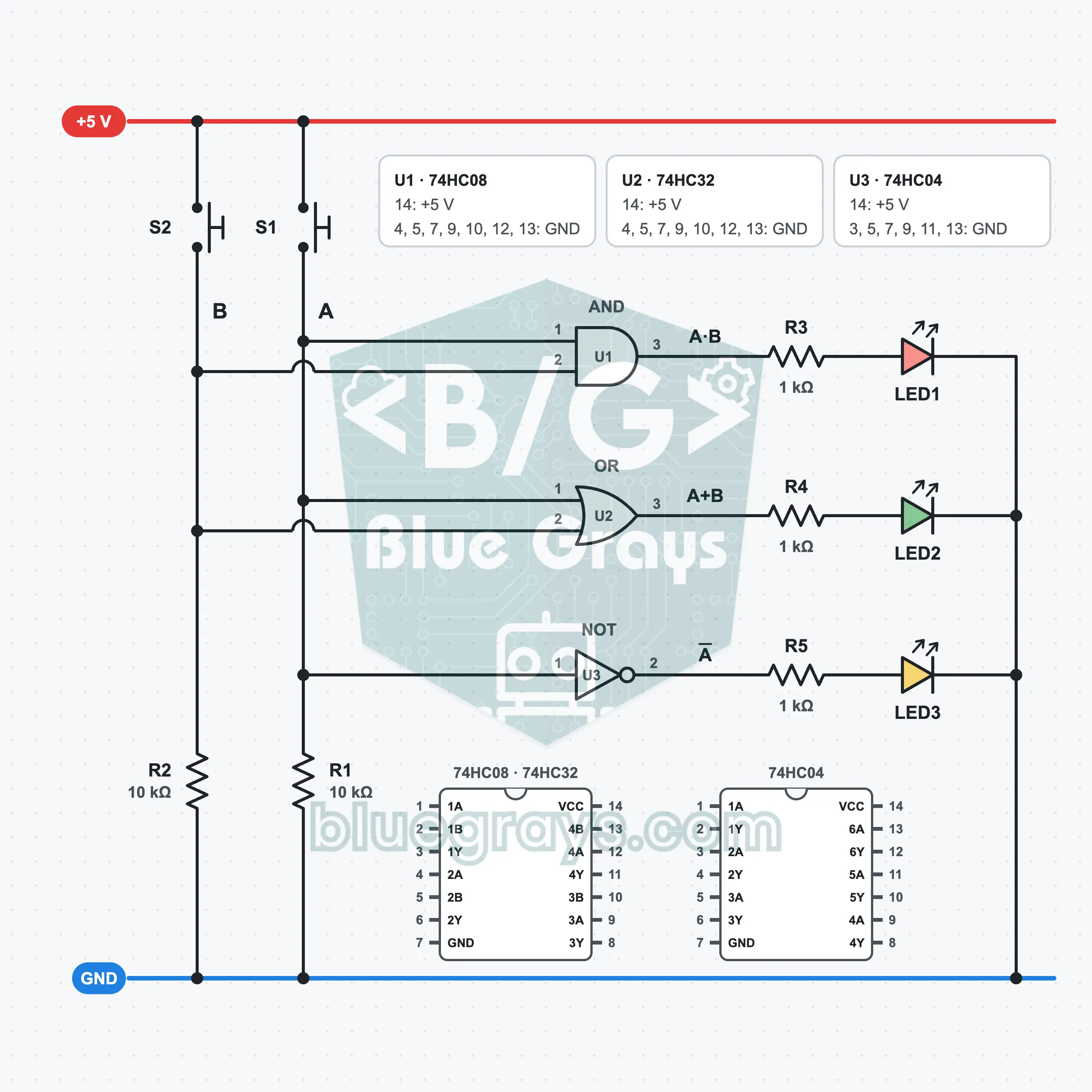
Basic Gates: AND, OR and NOT Circuit
Try out the three building blocks of digital electronics on the same breadboard. Two buttons become your A and B inputs; the red LED shows the result of the AND gate, the green LED the OR gate and the yellow LED the NOT gate. With the 74HC08, 74HC32 and 74HC04 ICs you try the four button combinations one by one and work out the truth table with your own eyes.
NAND and NOR: Inverting Gates
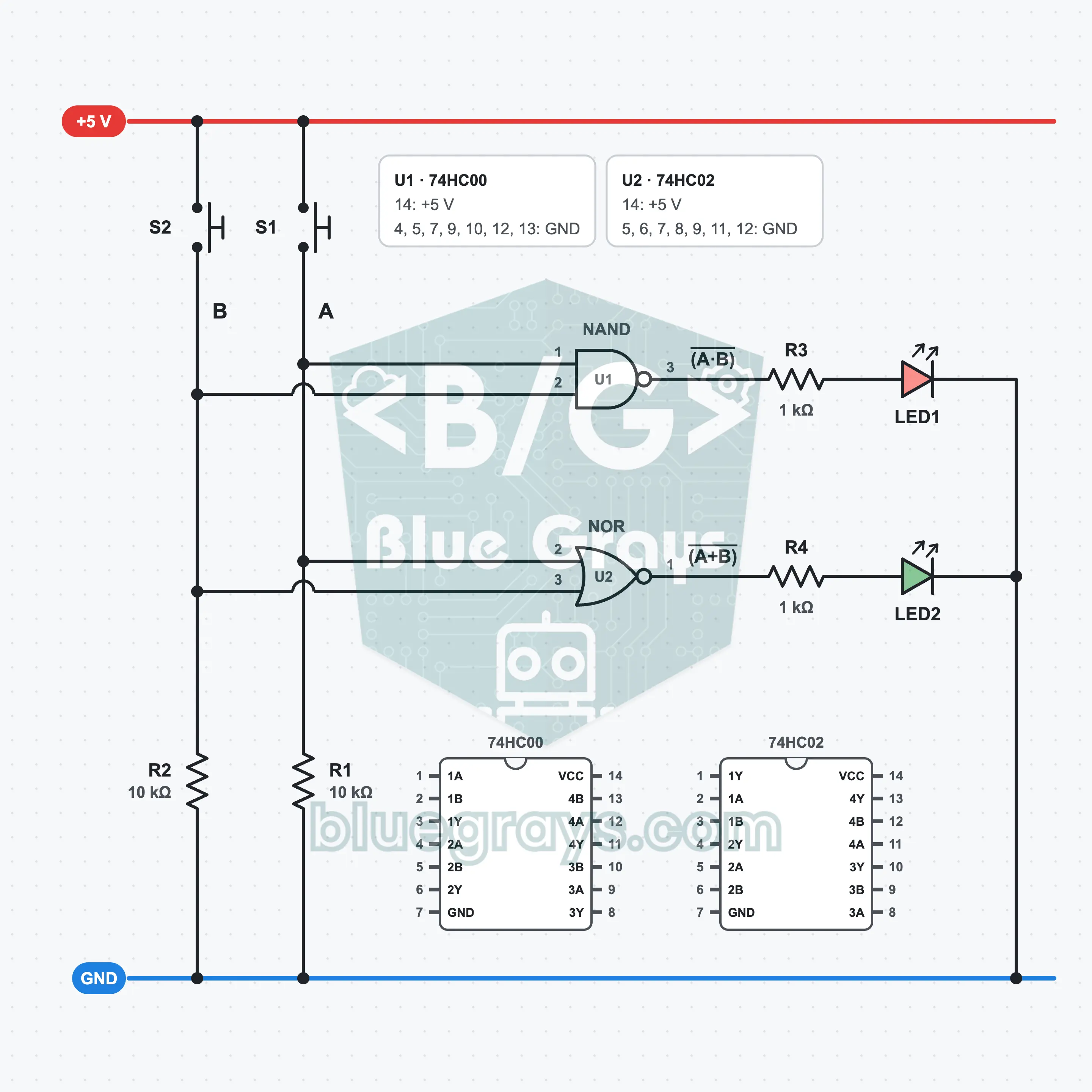
Build two inverting gates side by side with the 74HC00 and 74HC02 ICs. NAND is the opposite of AND; NOR is the opposite of OR. Two buttons give you inputs A and B; the red LED shows the NAND result and the green LED the NOR result. Without touching the buttons, both LEDs are on. Try the four combinations in turn, work out the truth table yourself and get to know the different pinout of the 74HC02.
Every Gate from NAND: One IC, Three Operations
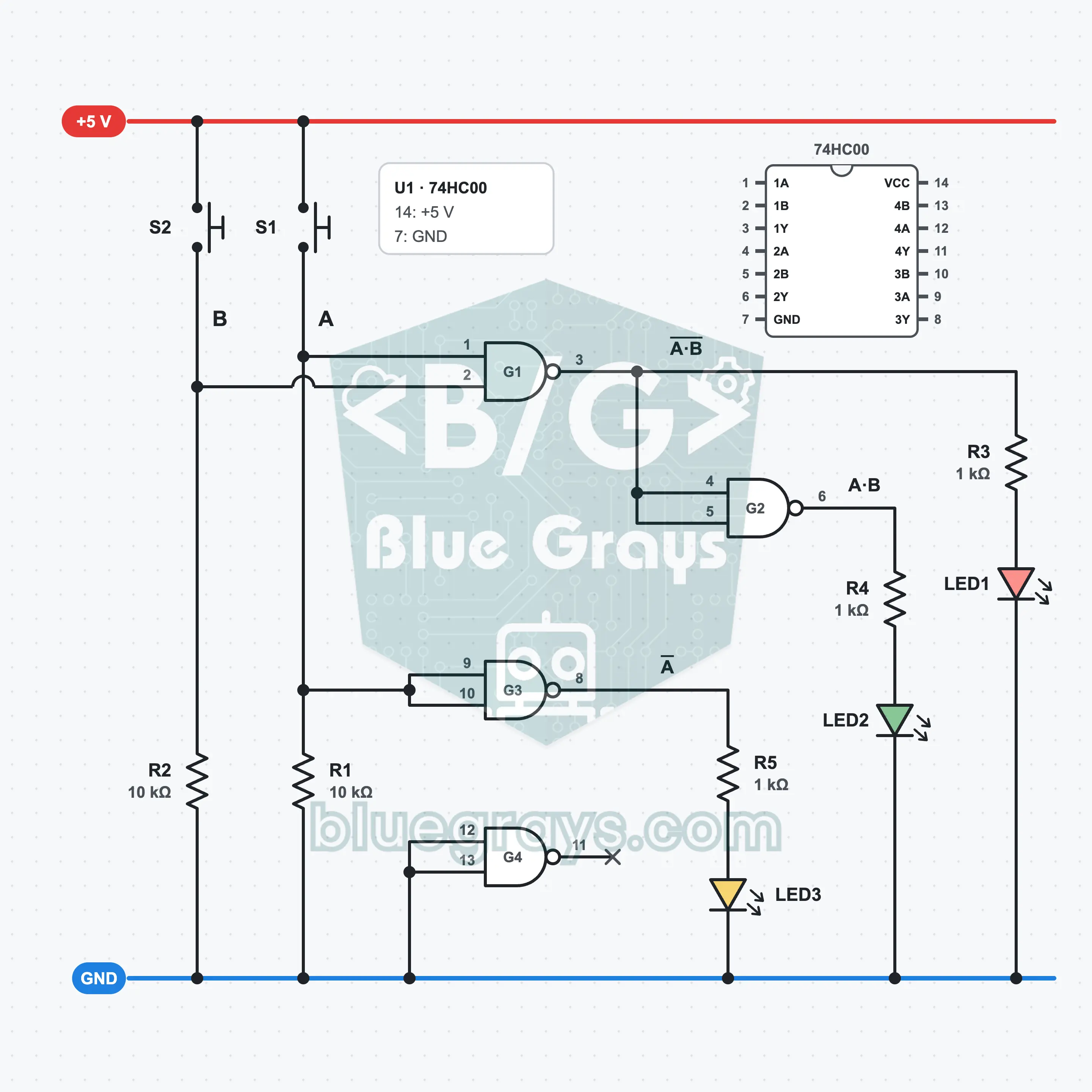
Build the NAND, AND and NOT gates at the same time with a single 74HC00 IC. The NAND gate is universal: with enough NANDs, every logic circuit can be made. Two buttons become your inputs; the red LED shows the NAND result, the green LED the AND result and the yellow LED the NOT result. In the task you also get an OR gate out of the same IC.
XOR: The Gate That Spots the Difference
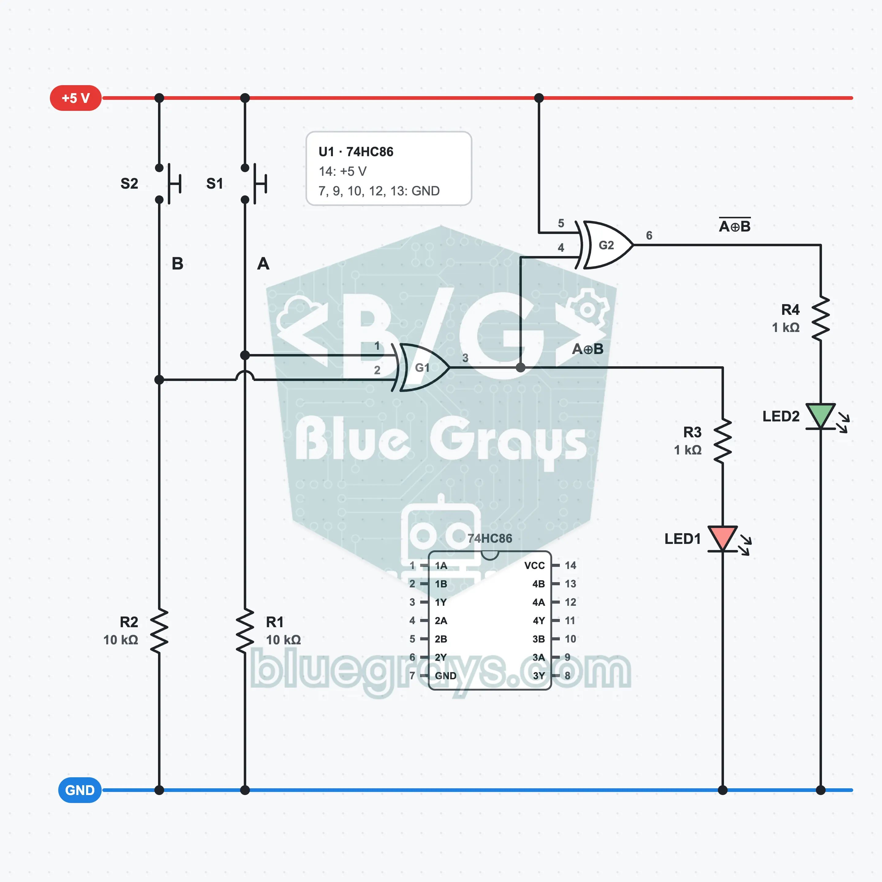
Build the XOR gate with the 74HC86 IC: its output is 1 when its two inputs differ. Two buttons become your inputs; the red LED shows the XOR result, the "there is a difference" signal. A second XOR gate is wired as an inverter and gives the XNOR result on the green LED: it lights when the inputs are equal. This way you build a small comparator that checks whether two bits are equal.
SR Latch: 1-Bit Memory with Two NOR Gates
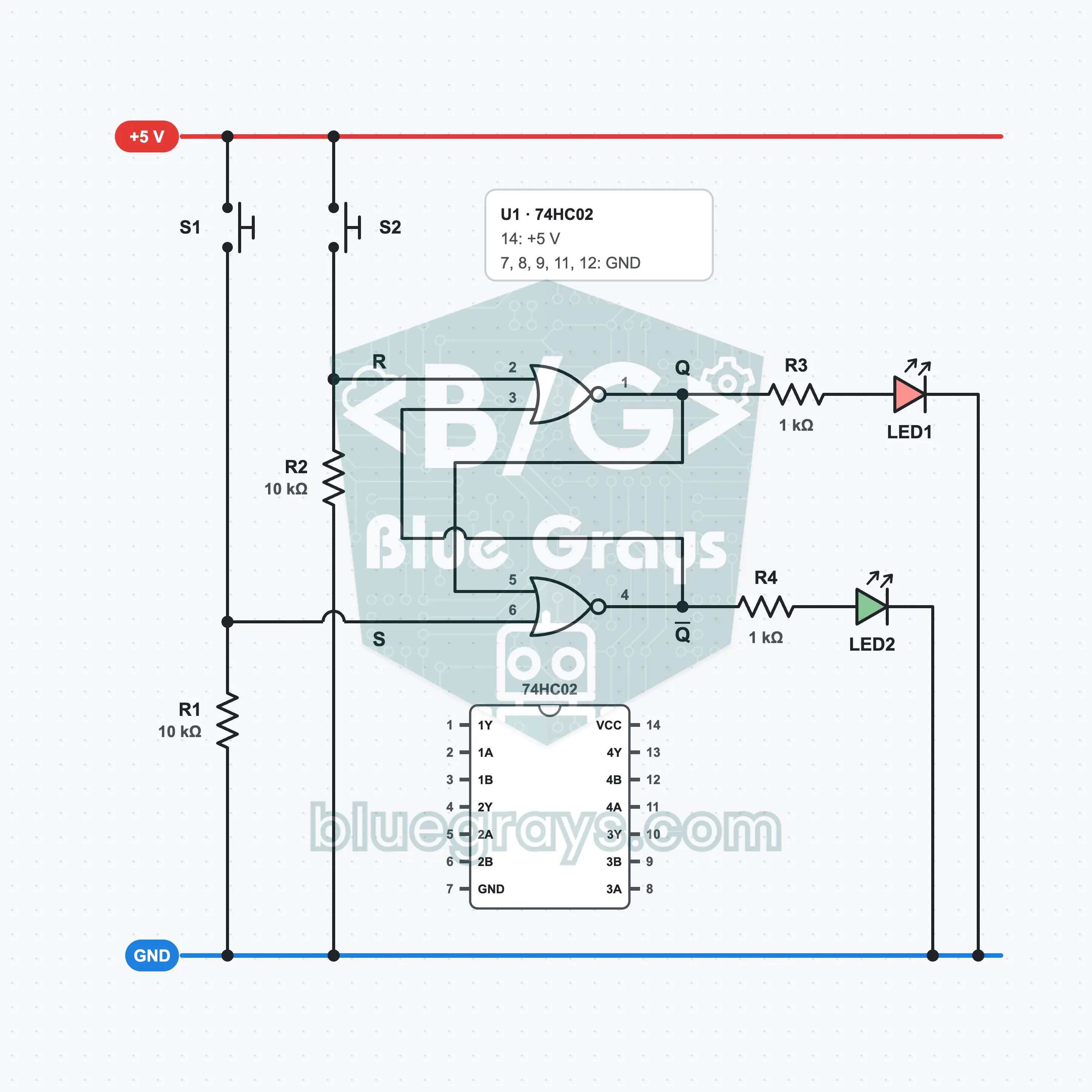
Cross-couple two NOR gates and you have a 1-bit memory. This SR latch, which you build with a 74HC02, sets the Q output to 1 when you press the S button, sets it to 0 when you press the R button, and keeps the last state when you release the button. This small structure is inside every flip-flop. You read the truth table off the LEDs and try out the forbidden state yourself too.
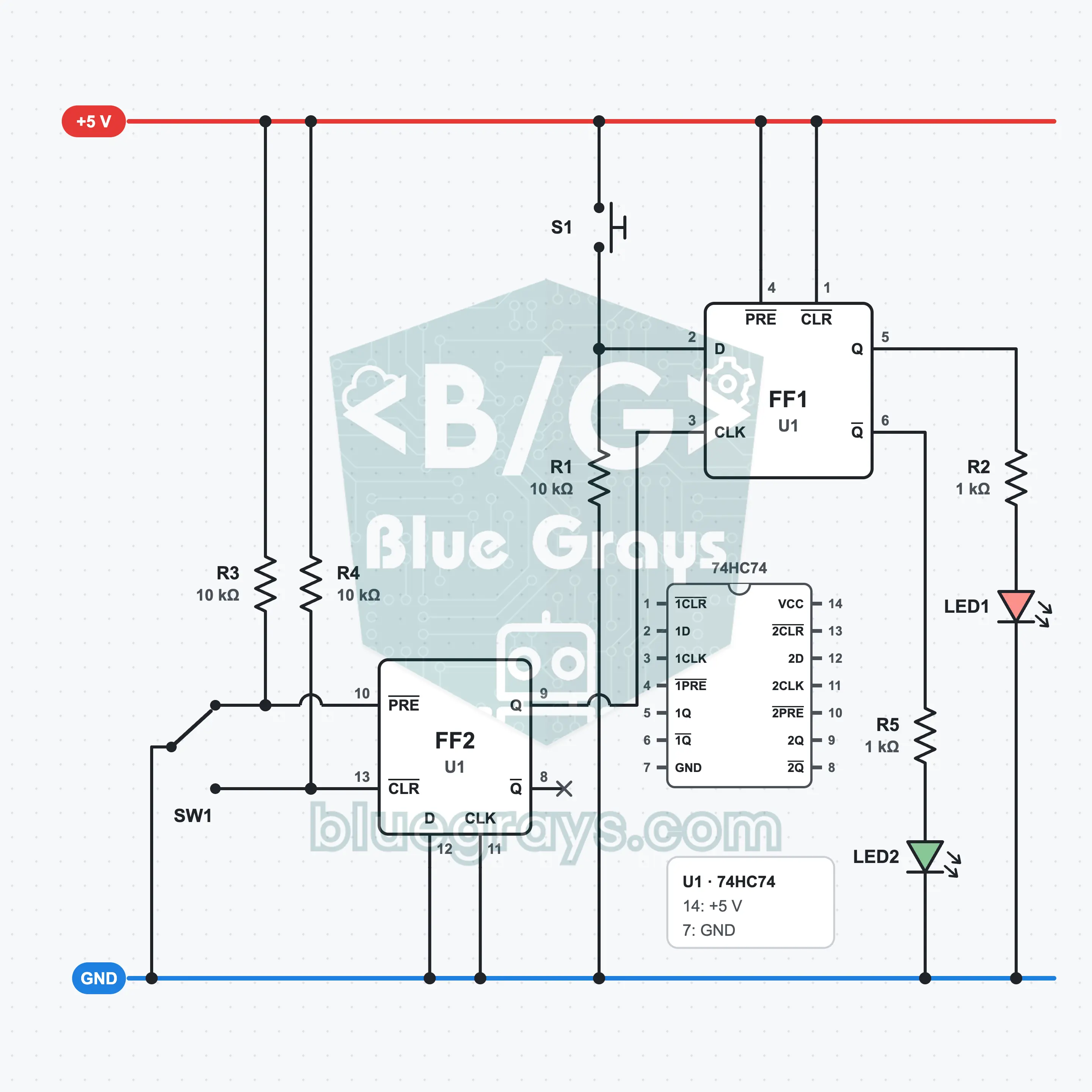
D Flip-Flop: 1-Bit Memory with the 74HC74
Build the smallest piece of computer memory yourself. The D flip-flop inside the 74HC74 takes the value on its D input the moment a clock pulse arrives and keeps it until the next pulse. You give the data with a button and the clock pulse with a slide switch; the red LED shows what is inside the memory. You see the rising edge concept with your own eyes.
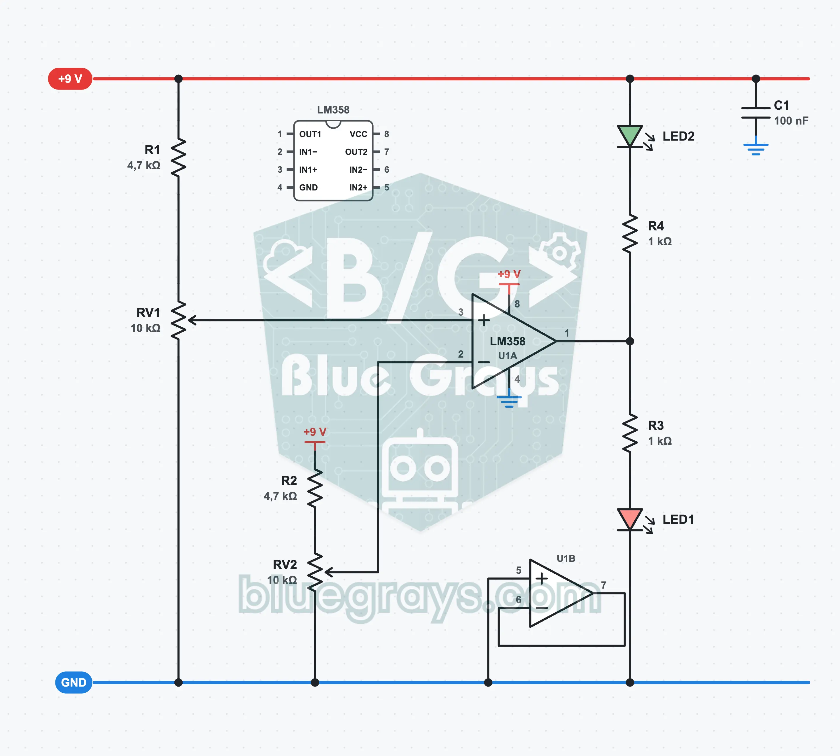
Comparator: Which Is Bigger?
Turn two pots: the LED of whichever has the higher voltage lights. Red if RV1 is ahead, green if RV2 is ahead. The LM358 works here as a comparator; it compares its + input and − input and pushes its output either to the top or to the bottom. A single output lights the two LEDs in turn. You learn about op-amp inputs, the input range and why the output flickers when the two voltages are equal.
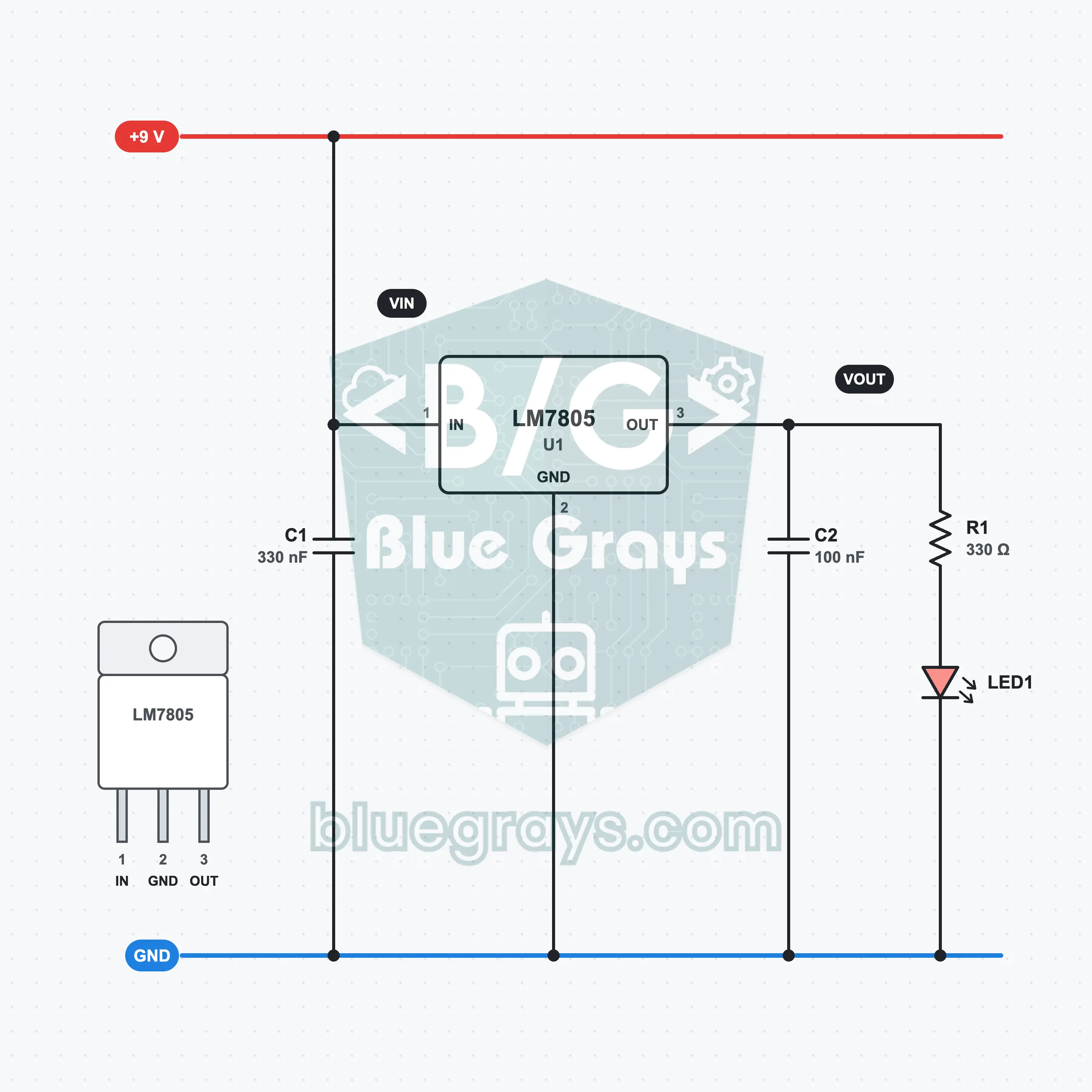
9 V to 5 V: A Fixed Voltage with the LM7805
Get a steady 5 V from a 9 V battery: the LM7805 keeps the excess voltage across itself, so even when the battery drops from 9.5 V to 7 V the output stays at 5 V and the LED always glows with the same brightness. You measure the input and the output with a multimeter. You learn about the fixed regulator, the job of the two capacitors, the dropout voltage, the power the regulator turns into heat, and why taking 5 V from a 9 V battery is inefficient.
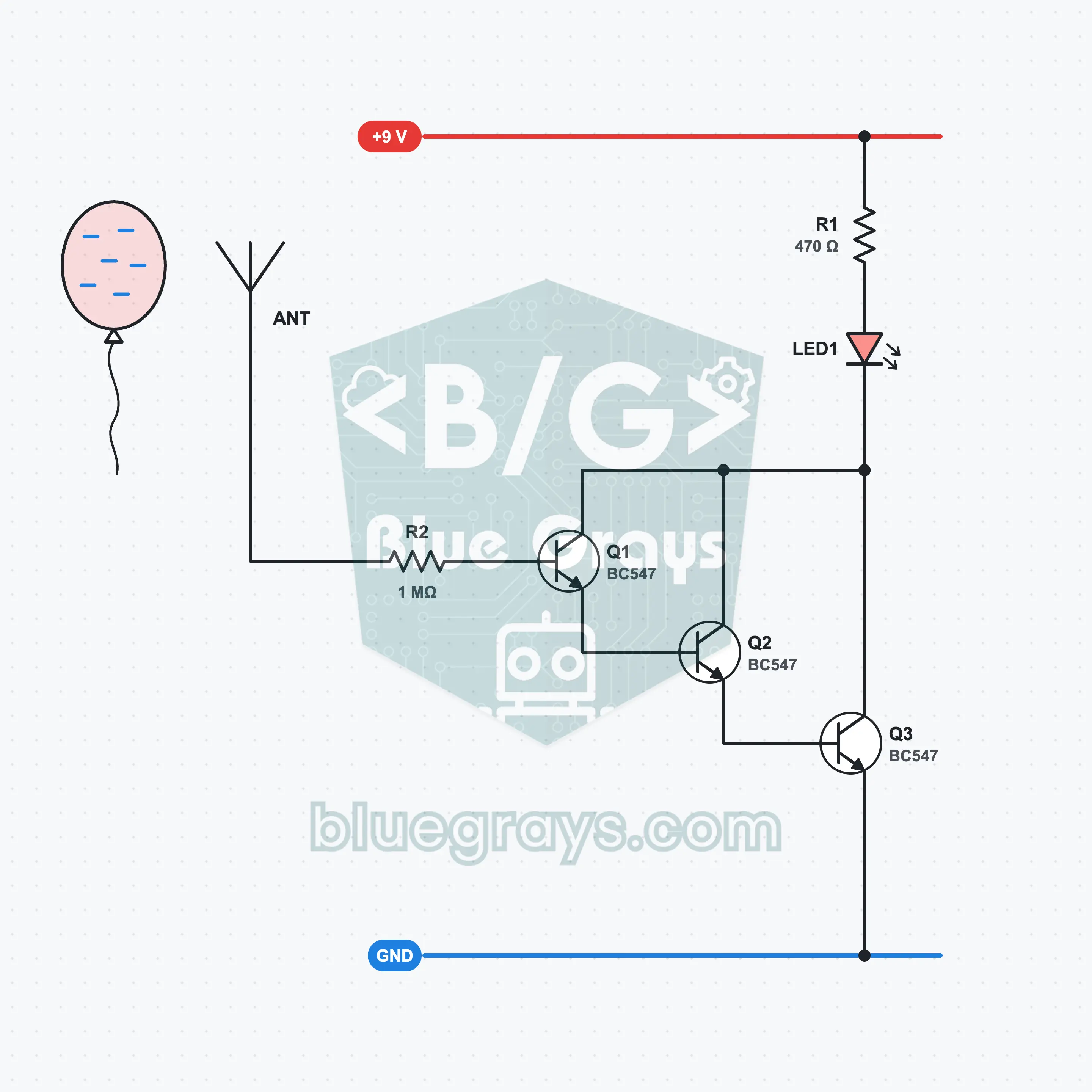
Static Electricity Detector
A charge detector that works without touching. Rub a balloon or a plastic comb on your hair, move it toward and away from a short antenna wire, and the LED turns on and off by itself. The secret is three BC547s connected in a row: each amplifies the current of the one before it and the total gain reaches millions. So the current the balloon creates in the antenna, which even a meter can hardly see, is enough to light an LED. You try out static electricity and how gains multiply.
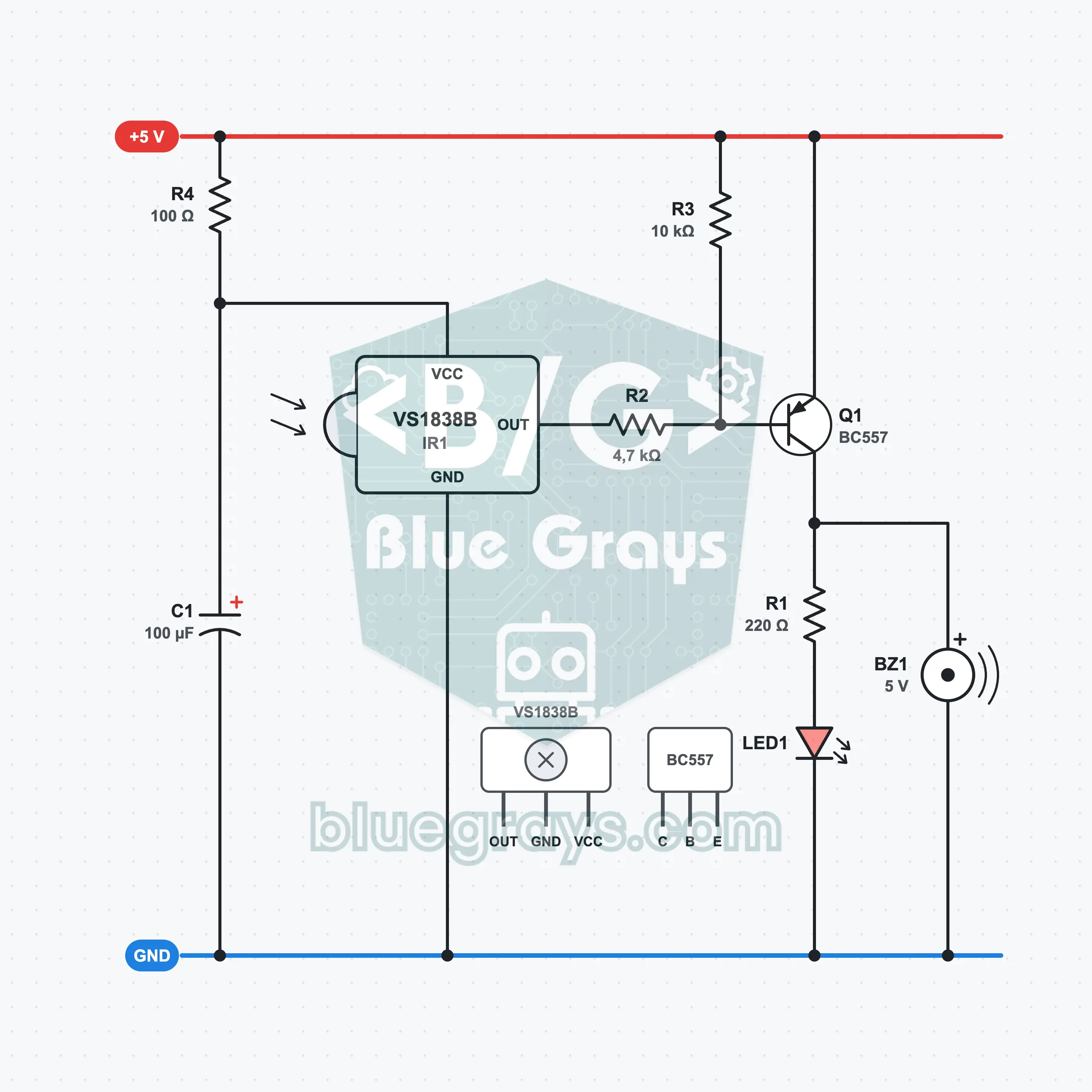
Remote Control Tester: See the Invisible Light
Press a button on a TV remote: the LED flickers and the buzzer crackles. The light at the tip of the remote is infrared, so your eyes cannot see it; the VS1838B receiver can, and it pulls its output low. A PNP transistor called the BC557 uses this low signal to drive an LED and an active buzzer. In a few seconds you find out which remote works and which one has a dead battery. It is also a good circuit for meeting the PNP transistor: it conducts while its base is low.
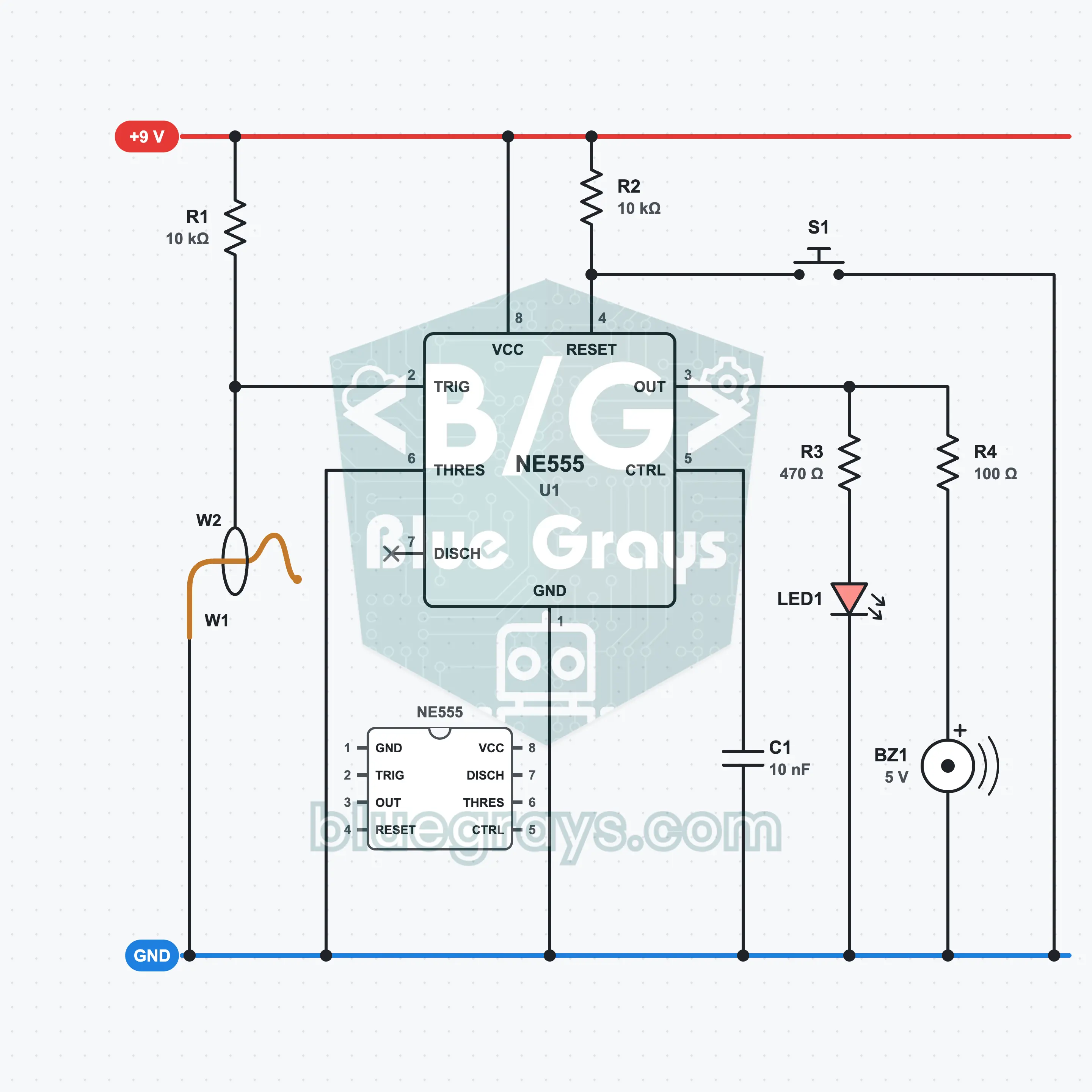
Steady Hand Game
Take the loop along the winding wire from end to end without touching the wire. Touch it and the buzzer sounds and the LED lights, and they stay on even if you pull the loop away: the circuit remembers the touch. Press the button to start again. The memory is an NE555 in bistable mode, which catches even the shortest contact. You bend the track yourself from bare copper wire: tighter bends make a harder game. As you test your steady hand, you also see SET and RESET logic.
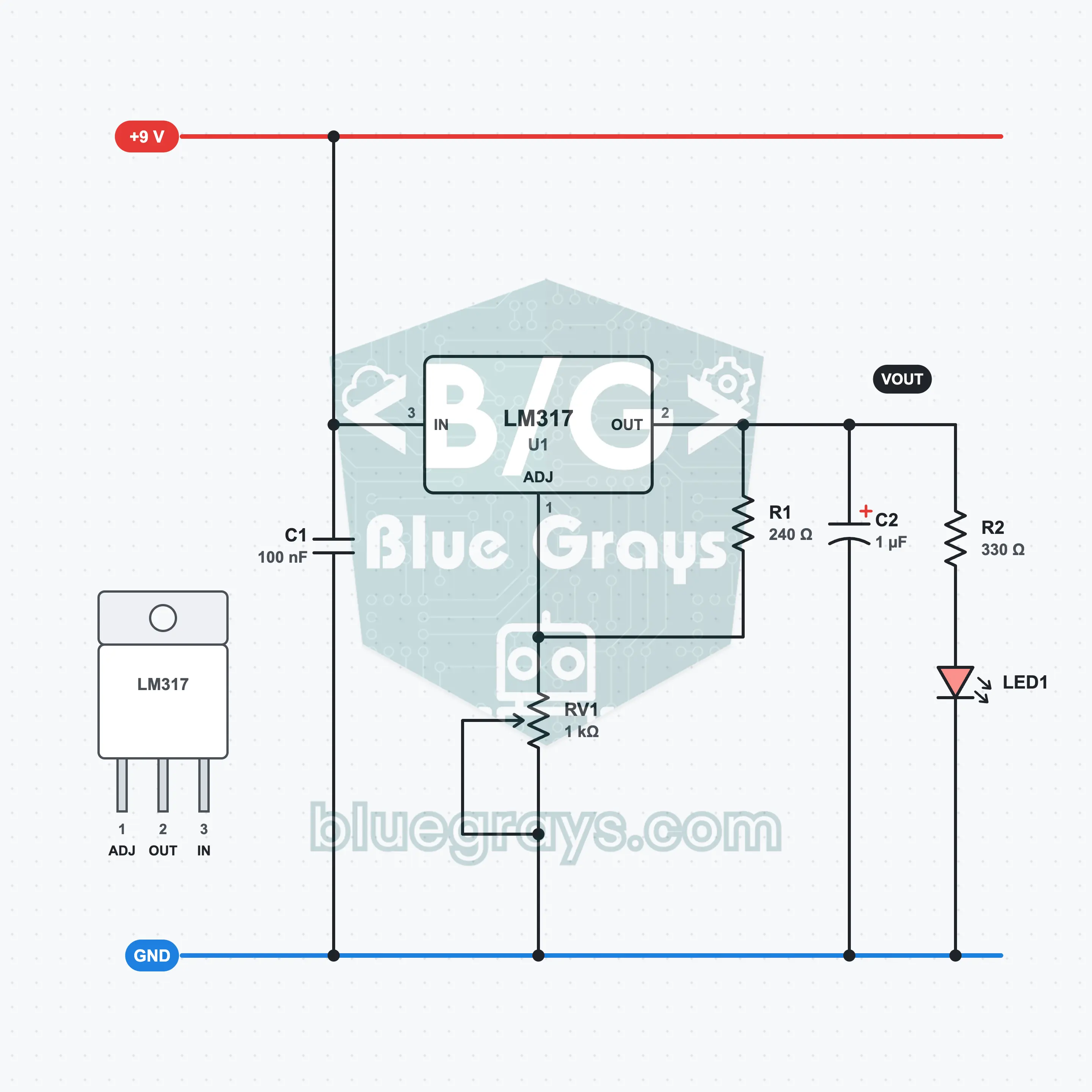
Adjustable Power Supply with the LM317
As you turn the pot, the output voltage changes between 1.25 V and about 6.5 V, and the red LED goes from off to bright. The LM317 always keeps 1.25 V between its output and its adjust pin; the ratio of two resistors sets the output. Even if the battery drops a little below 9 V, the voltage you set stays steady. You learn about the linear regulator, the adjustment formula, the dropout voltage and how excess voltage turns into heat.
O‘rta daraja54 ta sxema
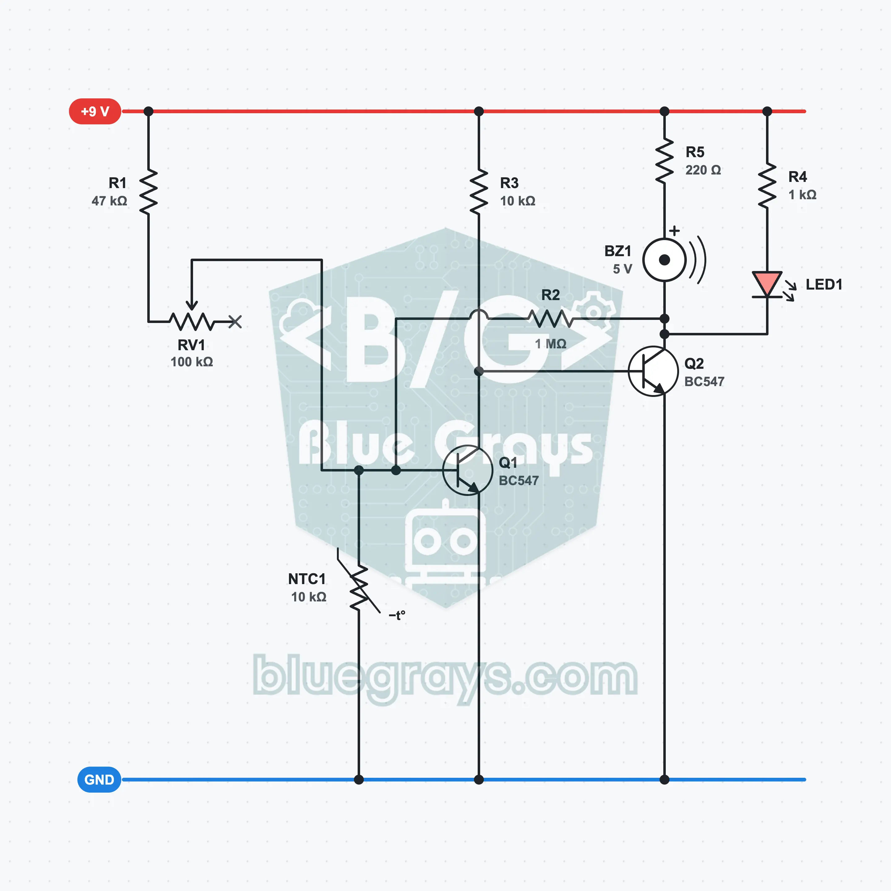
Temperature Alarm: Two-Transistor Heat Warning with an NTC
A temperature alarm that sounds when the surroundings warm up. The resistance of an NTC thermistor drops as the temperature rises; this change in a voltage divider triggers a switch built with two BC547s, the active buzzer sounds and the LED lights. You set the threshold with a 100 kΩ pot between about 23 °C and 50 °C. A feedback resistor prevents crackling at the threshold. You try it out by holding the NTC between your fingers or warming it with a hair dryer.
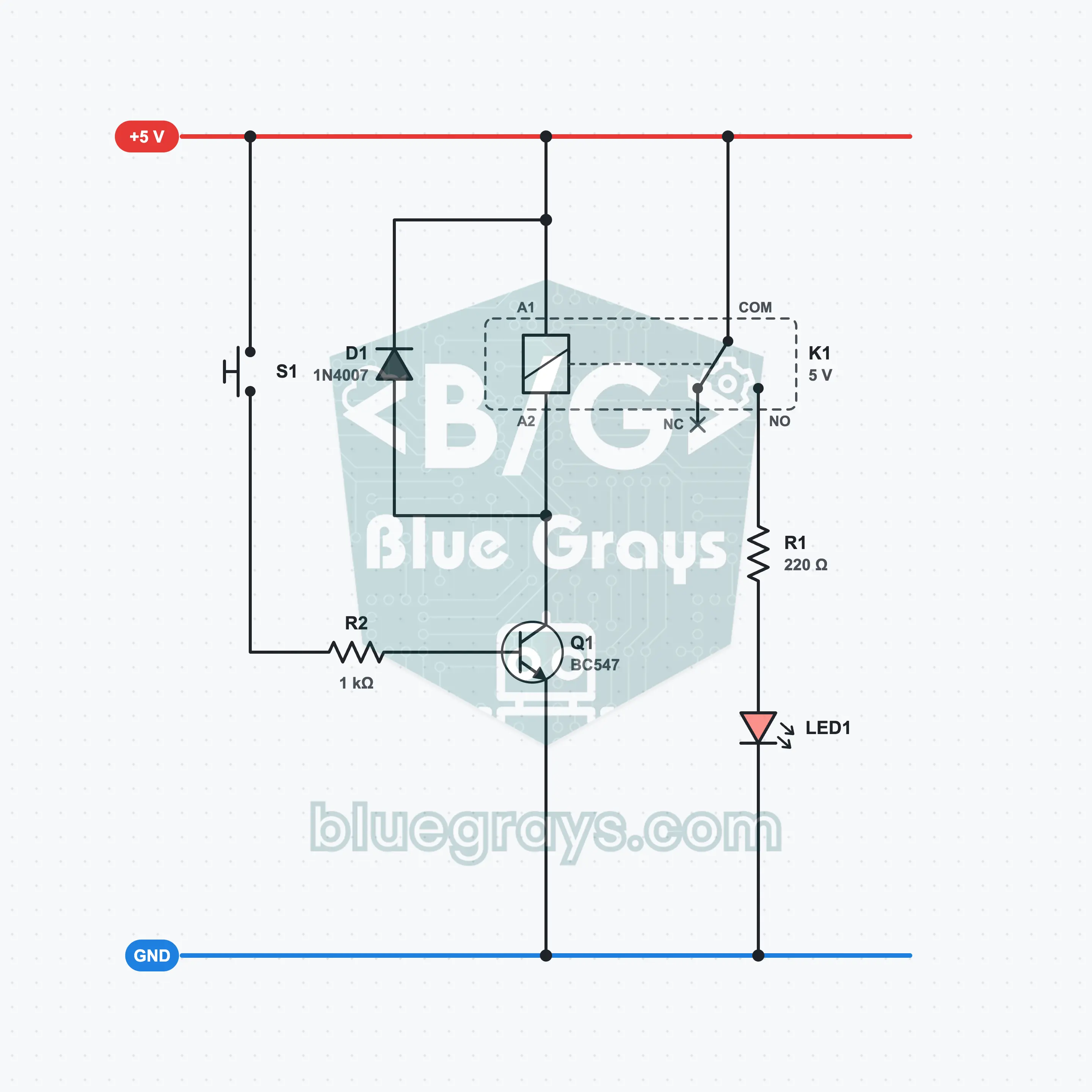
Driving a Relay: Relay Control with a Transistor and Diode
A relay is a mechanical switch that turns a completely separate circuit on and off with a small current. In this circuit, when you press the button the BC547 feeds current to the relay's coil, the contact closes with a click and the LED lights. The 1N4007 diode connected in reverse across the coil protects the transistor from the voltage spike that appears at turn-off. Here the contact only switches an LED at 5 V: never try mains voltage on a breadboard.
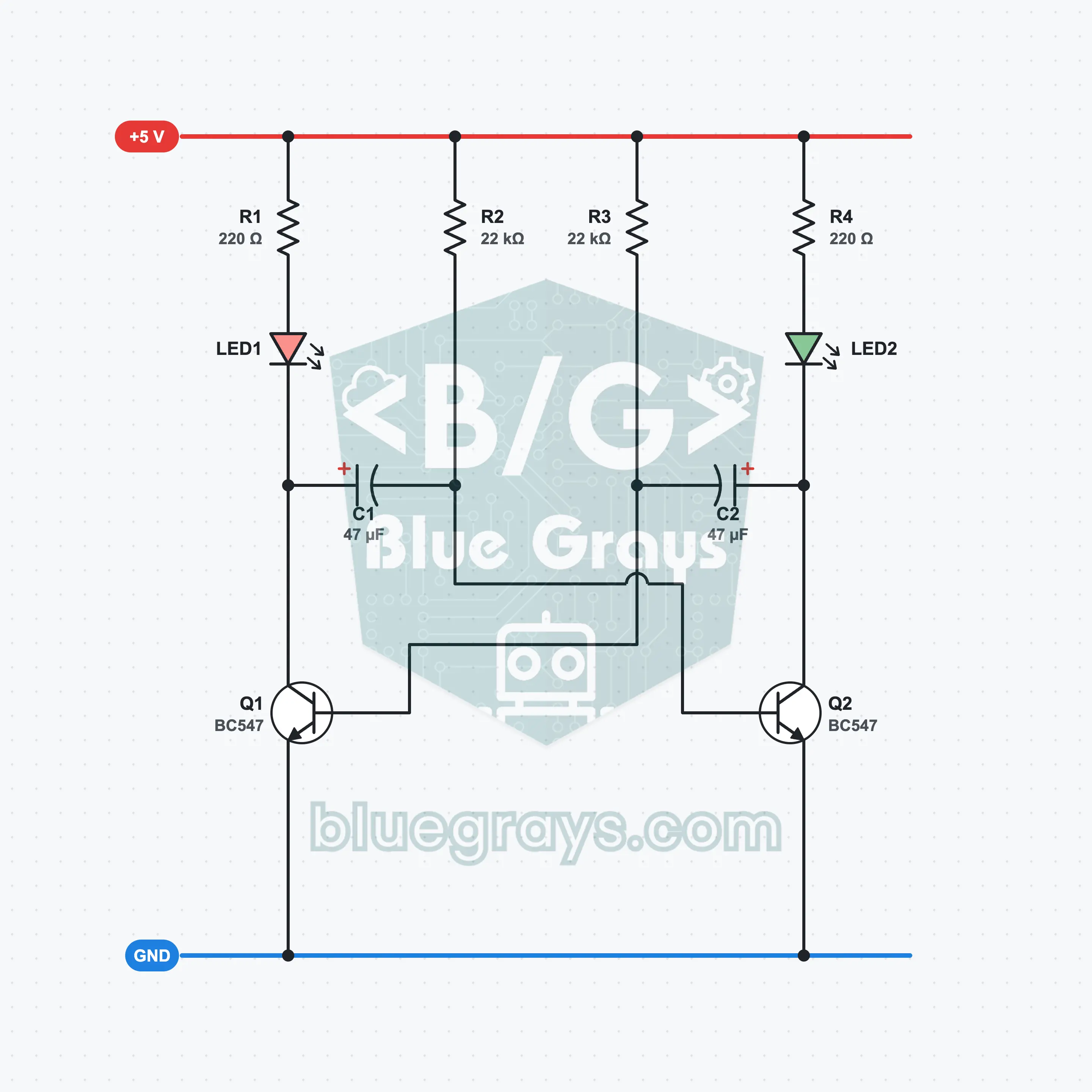
Transistor Flip-Flop: Two-LED Flasher Circuit
The classic flip-flop circuit that everyone starting out in electronics builds: with two BC547 transistors, two capacitors and four resistors, two LEDs flash in turn. No IC, no code. The real name of this circuit is the astable multivibrator; the transistors turn each other off in turn. You see how a capacitor silences a transistor and how the time is set by R × C.
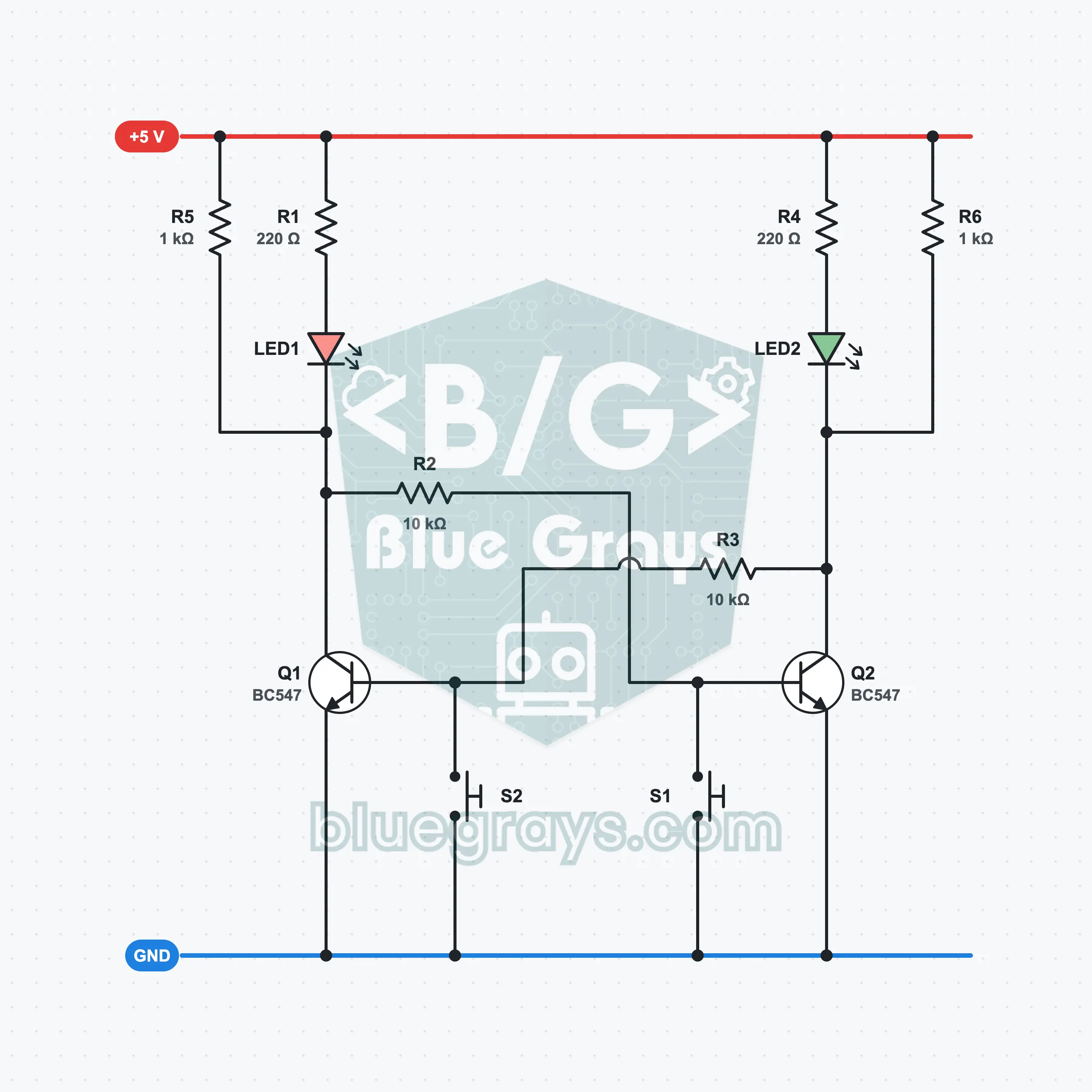
Transistor Memory: Two-Button Flip-Flop Circuit
Two BC547 transistors latch each other and become a 1-bit memory: when you press S1 the red LED lights, when you press S2 the green LED lights, and it stays that way even after you release the button. No capacitor, no IC. This circuit is the bistable multivibrator, that is, the transistor version of the real flip-flop. You see how the smallest piece of computer memory works by building it with your own hands.
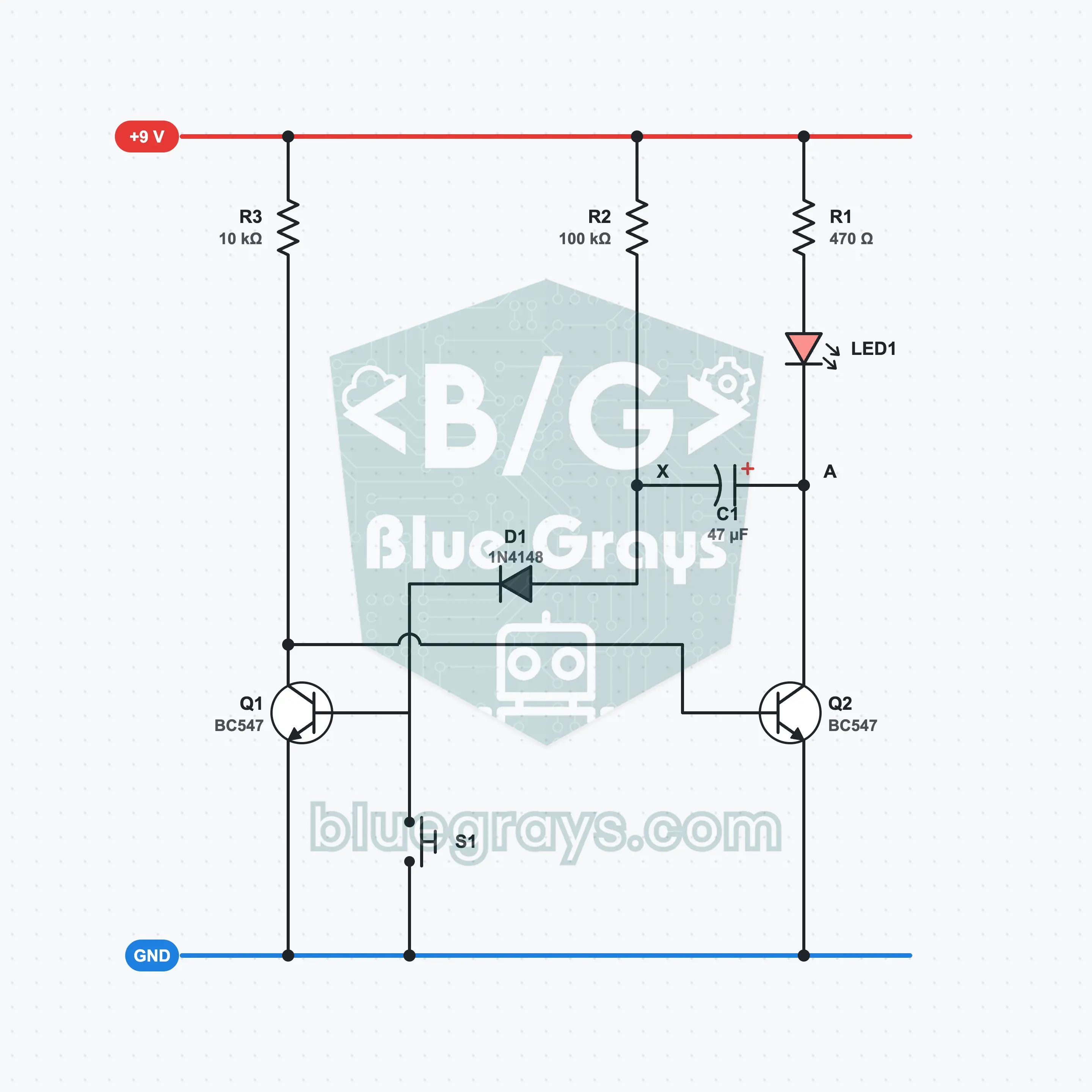
Transistor Timer: Press the Button, Light for 3 Seconds
Press the button once: the LED lights at once and goes out by itself after about 3 seconds. There is no IC; two BC547 transistors and a 47 µF capacitor keep the time. This circuit is a monostable multivibrator: it has a single stable state, and when nudged it switches to the other state for a while and then returns. R × C sets the time; on a 9 V battery you also see the job of the 1N4148 diode that protects the transistor.
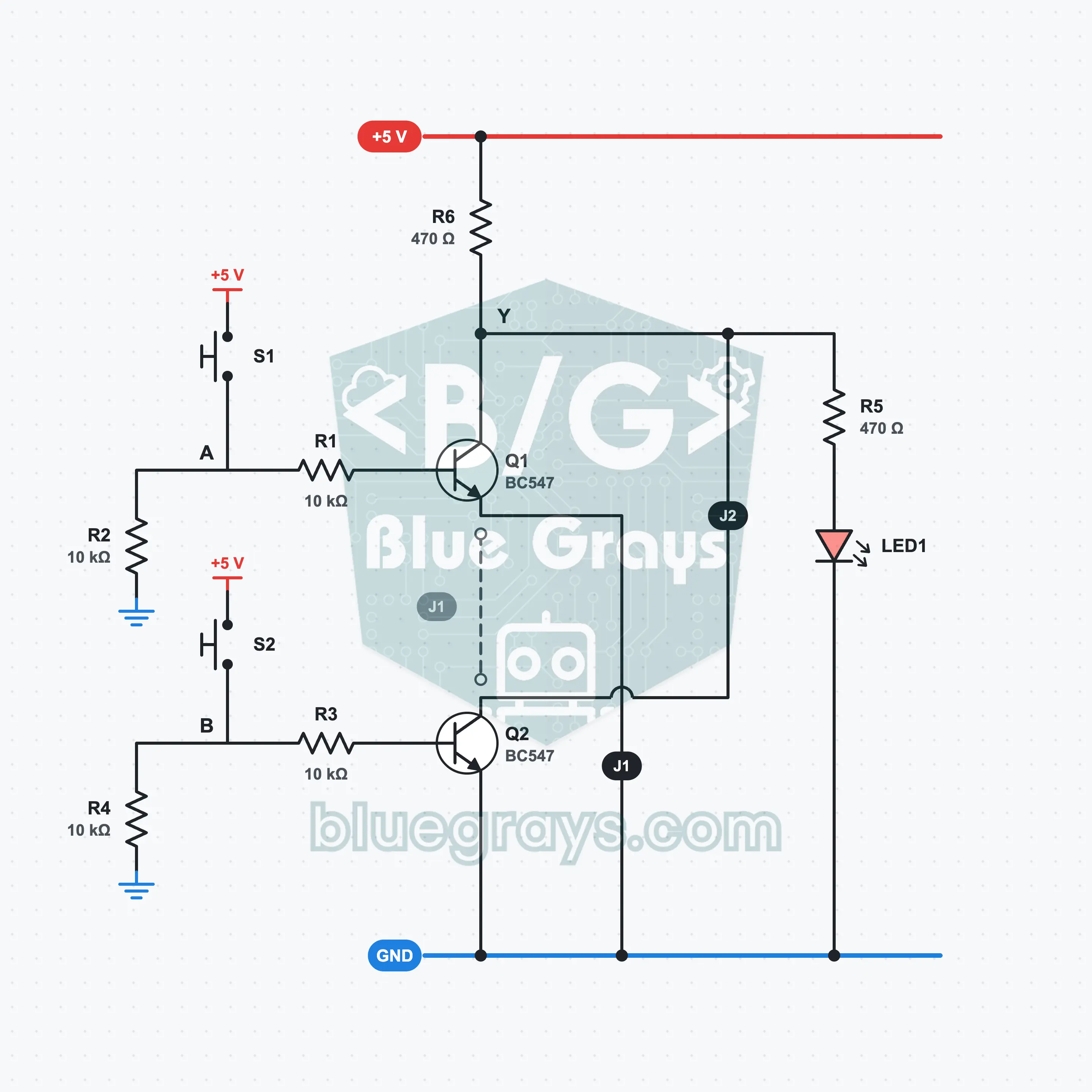
Logic Gates with Transistors: NOT, NOR and NAND
Build what is inside a logic gate IC yourself with two BC547s. Two buttons are the inputs A and B, and the LED shows the output Y: if the LED is on, the output is 1. By moving two jumper wires you turn the same circuit into a NOT, NOR or NAND gate: one transistor inverts, two side by side make a NOR, and two stacked make a NAND. You fill in the truth table of each gate with your own fingers.
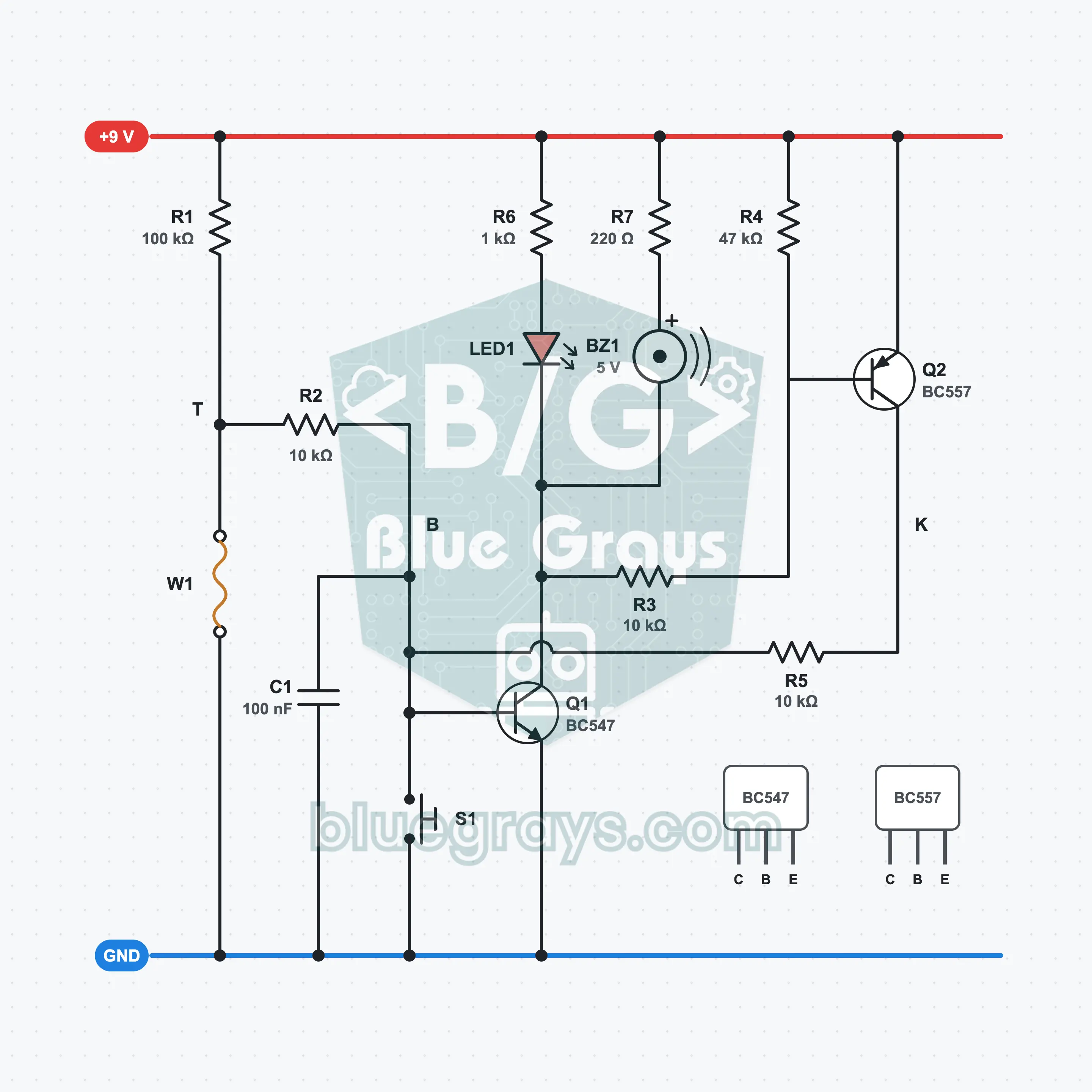
Broken Wire Alarm: A Two-Transistor Latching Alarm
Stretch a thin wire across a door or the lid of a box: the moment the wire breaks the buzzer sounds and the LED lights. Even if the wire is reconnected, the alarm does not stop; only the reset button silences it. The secret is a BC547 and a BC557 keeping each other on: the two transistors latch like a thyristor. While waiting, it draws only about 0.09 mA from the battery.
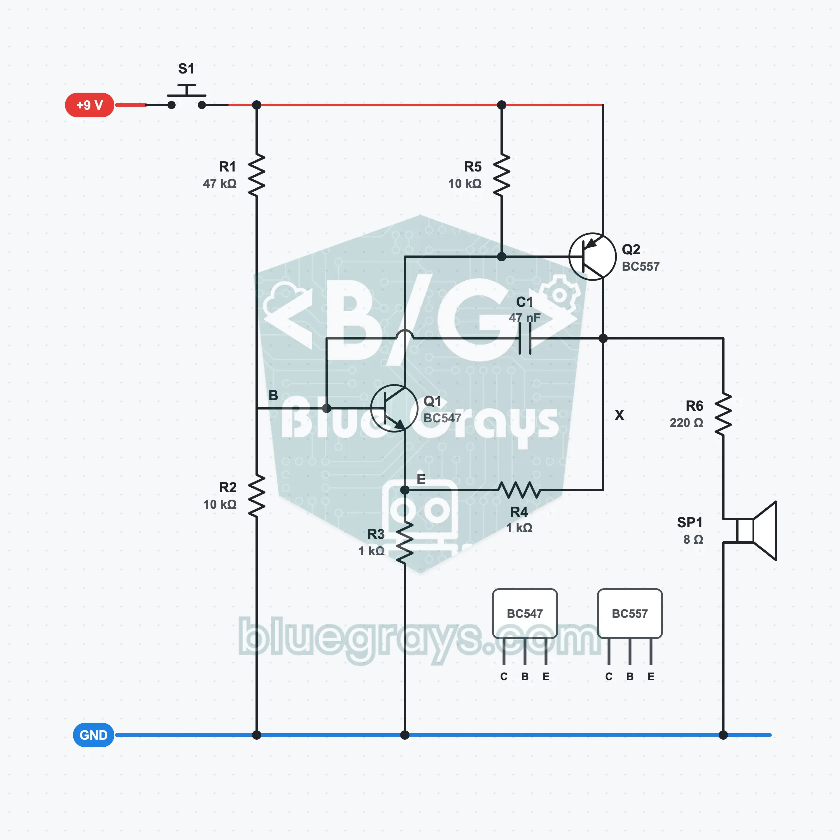
Two-Transistor Beep Circuit: A Tone with the BC547 and BC557
While you hold the button, the speaker gives a beep of about 1 kHz. There is no IC: a BC547 (NPN) and a BC557 (PNP) make the sound together; this pair is called a complementary pair. The tone is set by a 47 nF capacitor and two resistors. A 220 Ω resistor in series with the speaker keeps the transistor far below its 100 mA limit.
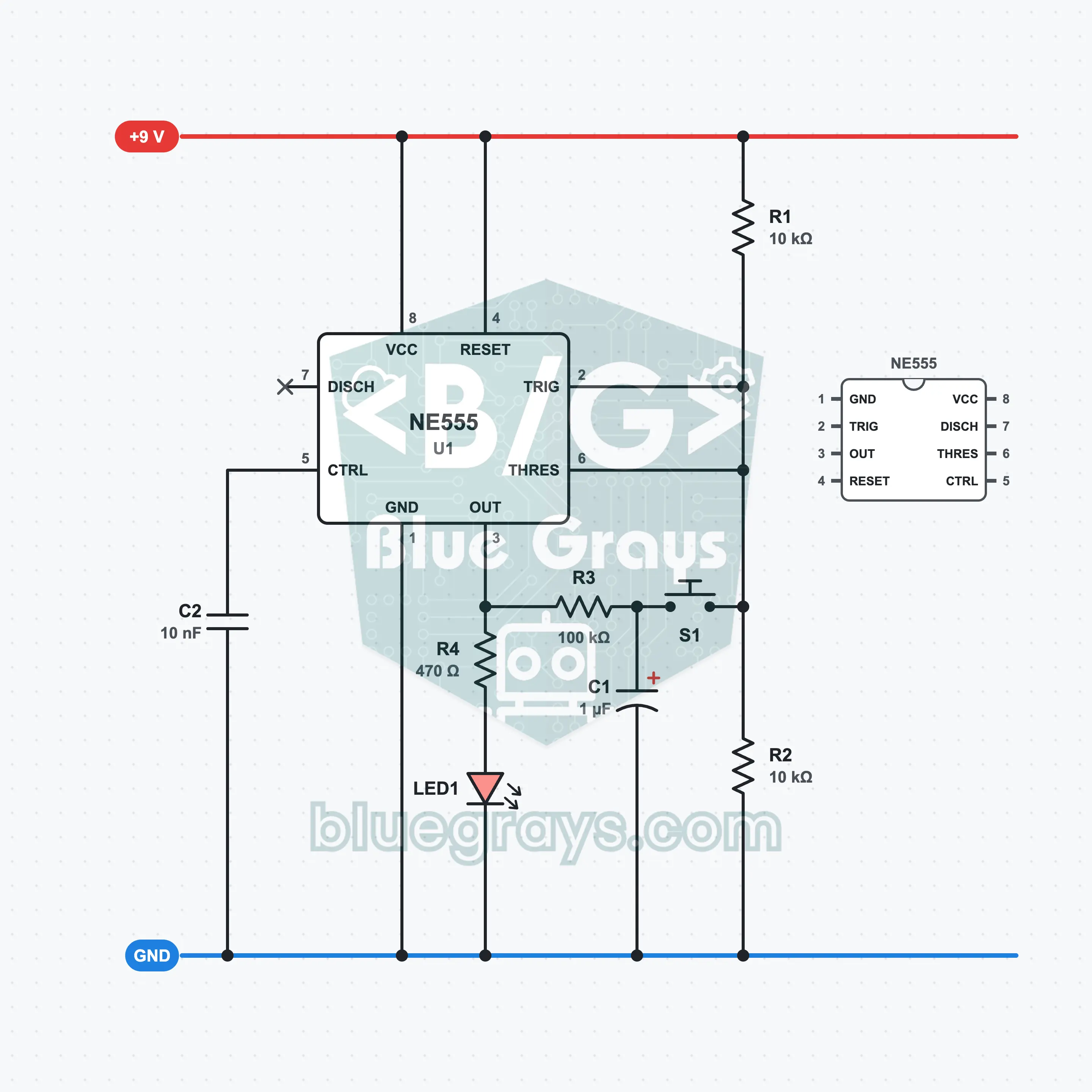
One-Button On/Off: Press to Light, Press to Switch Off with the 555
Press the button once and the LED lights; press again and it goes out. It works like a single-button lamp switch. The two inputs of the NE555 are joined and held at half the supply; a 1 µF capacitor remembers the last state of the output. When you press the button, this capacitor is connected to the input and pushes the 555 to the opposite state. The same capacitor also filters switch bounce: one press, one change.
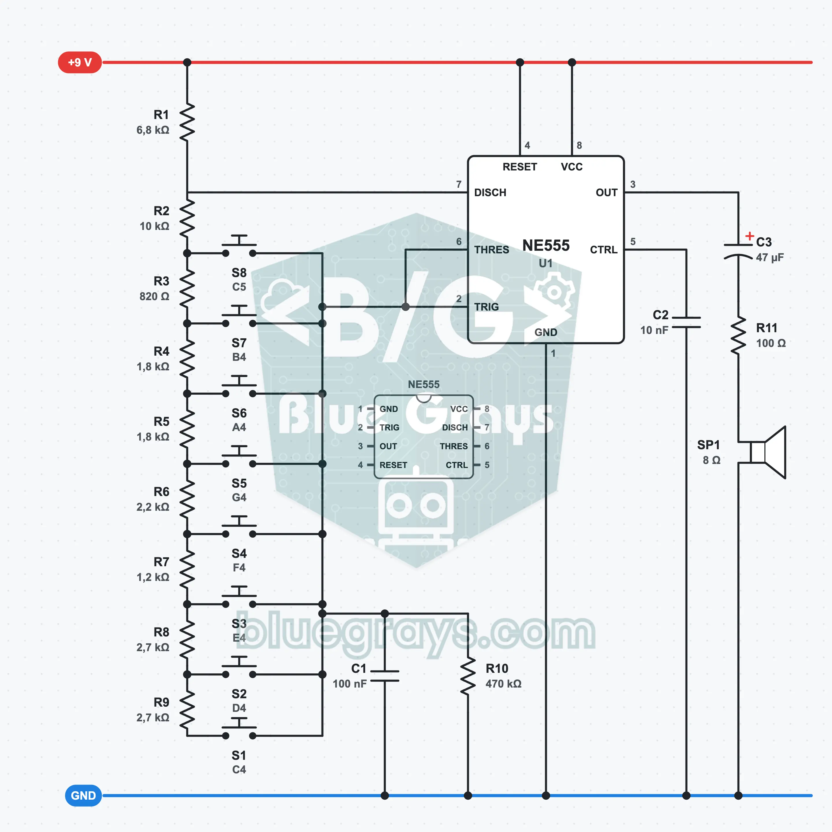
Mini Piano: An Eight-Key Octave with the 555
Press the eight keys in turn and the speaker plays Do, Re, Mi, Fa, Sol, La, Si and a high Do. A single NE555 makes the sound; the keys take the timing resistance of the 555 from different points of a series resistor chain. The notes lie between about 264 and 526 Hz, and in the simulation they are off target by at most 16 cents (one sixth of a semitone). With no key pressed the circuit stays silent; if you press two keys at once, the higher one sounds.
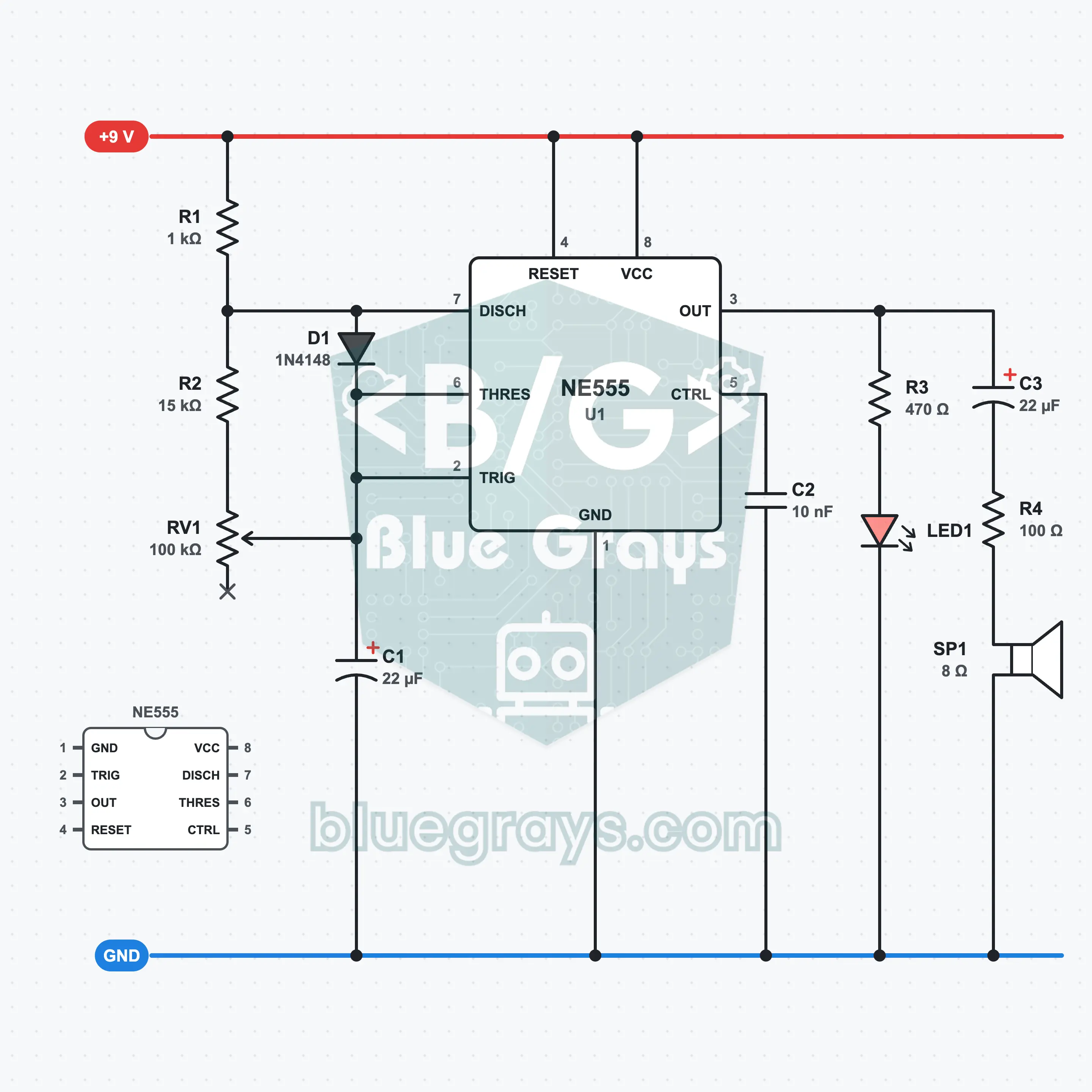
Metronome: Adjustable Tempo and Click Sound with the 555
Turn the pot to change the tempo: the speaker gives regular clicks and the LED blinks on every beat. The tempo can be set from about 32 to 230 beats per minute (BPM), which covers the 40 to 208 range of mechanical metronomes. A diode next to the NE555 keeps the output high for only 18 ms on each beat, so you hear a short click, not a long beep. The pot position and the tempo are not linearly related.
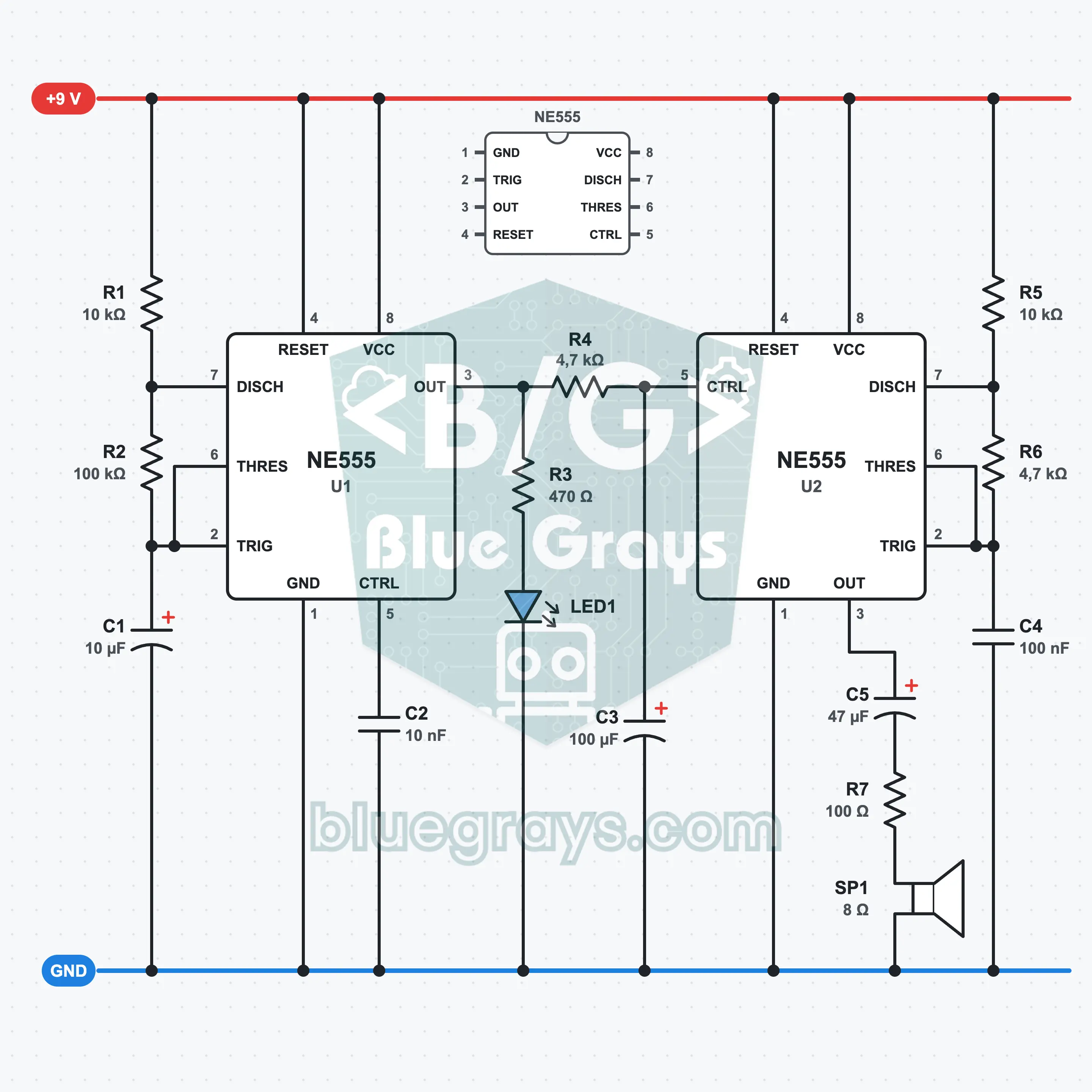
Police Siren: A Rising and Falling Sound with Two 555s
Connect the battery and the speaker gives a siren that rises and falls like wee-woo, while a blue LED blinks in the same rhythm. The first, slow NE555 is connected to pin 5 (CTRL) of the second one and keeps shifting its thresholds. The tone sweeps between about 620 Hz and 1300 Hz, once every 1.45 seconds. Do not hold the speaker close to your ear.
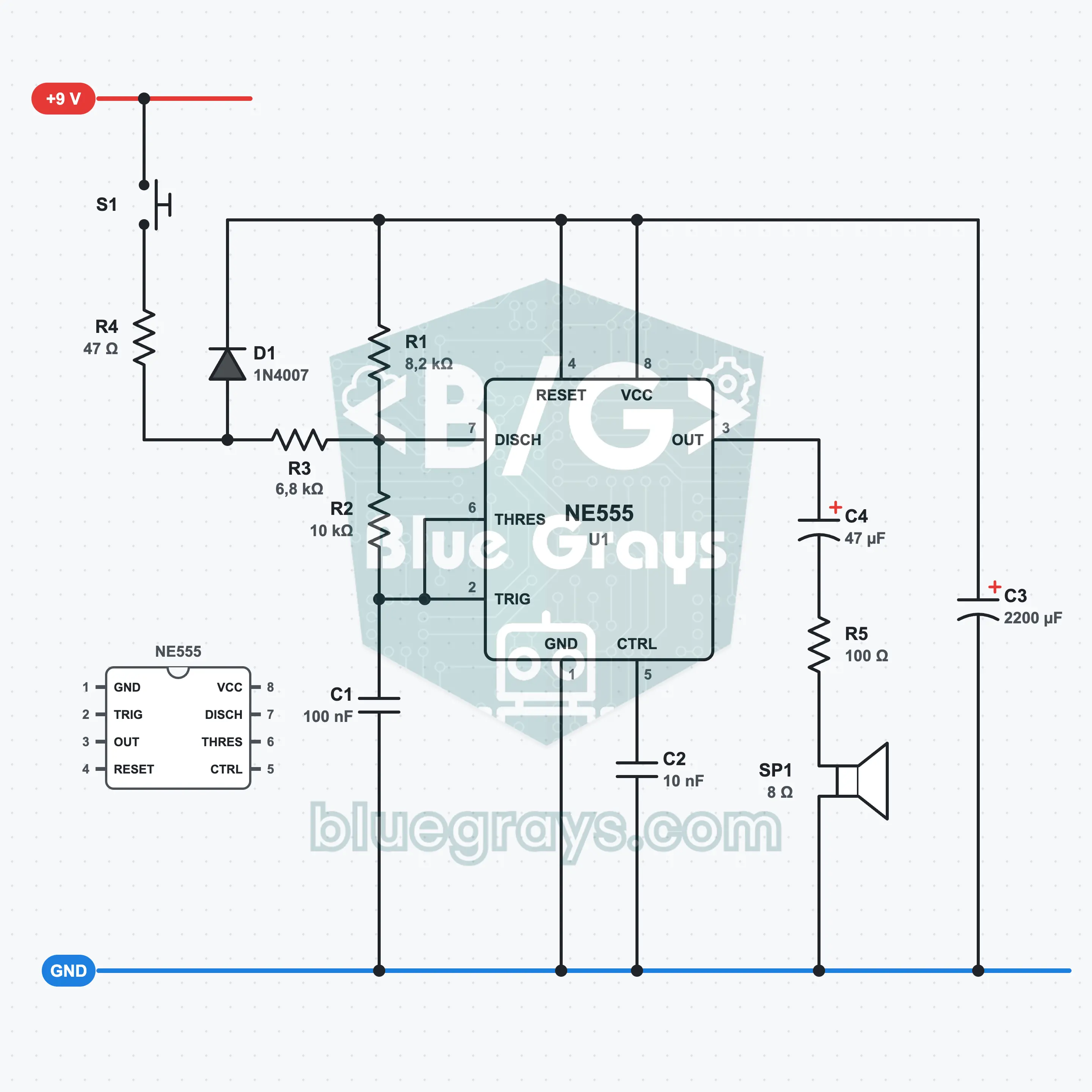
Two-Tone Doorbell: A Ding Dong Sound with the 555
Press the button: the speaker gives a high ding at about 640 Hz. Let go: the sound drops to 510 Hz, becomes the dong and fades out in about 1.3 seconds. A single NE555 makes both tones; the dong is played by the 2200 µF capacitor charged through the button. When the button is not pressed, the circuit draws no current at all from the battery, so it can stay connected.
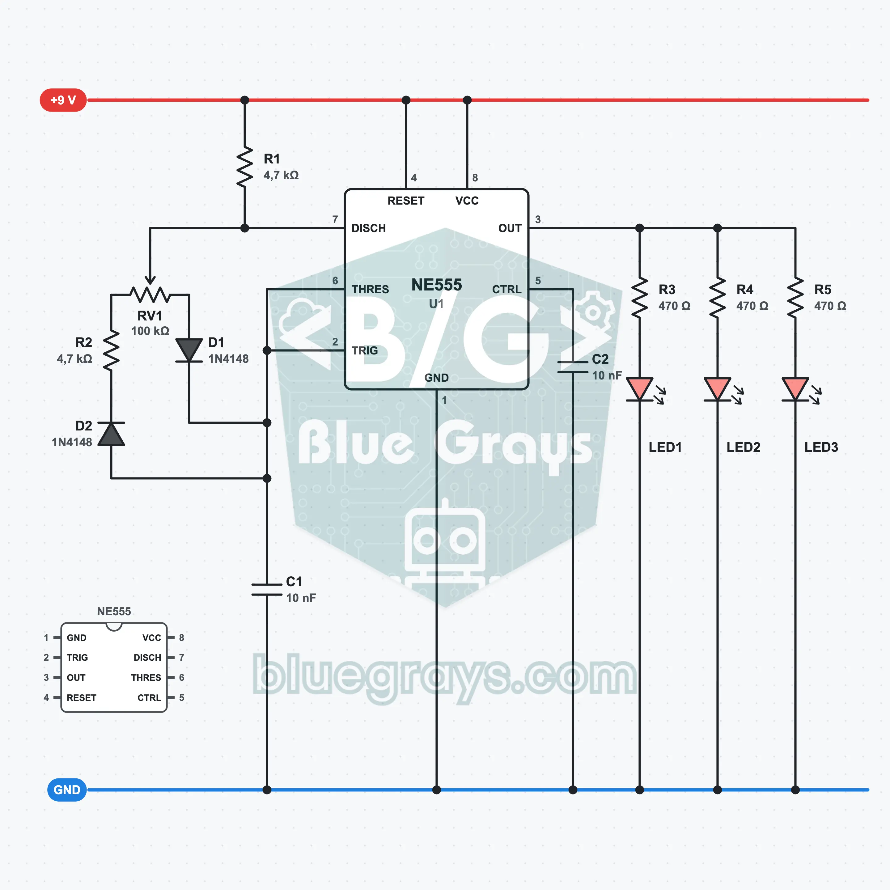
PWM LED Dimming: Brightness Control with a 555 and a Pot
Turn the pot and three LEDs go from almost off to fully bright. The NE555 switches on and off about 1200 times per second; the pot and two diodes keep the frequency almost constant while changing the share of each cycle it stays on, the duty, between about 4% and 95%. The LEDs always light with the same current, and your eye sees the average. This method is called PWM.
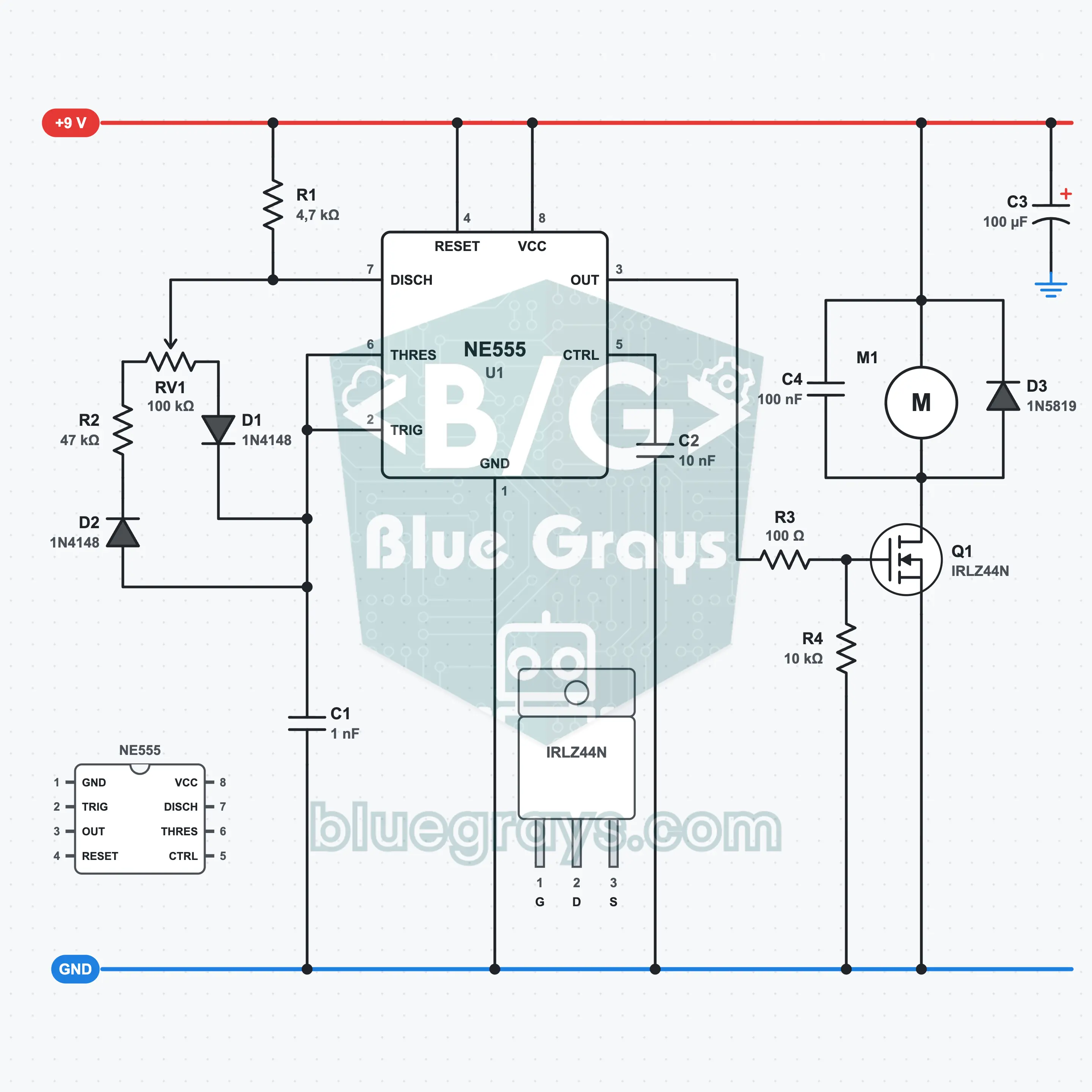
PWM Motor Speed: DC Motor Control with a 555 and a MOSFET
Turn the pot and the geared DC motor slows down or speeds up. The NE555 produces a signal that switches on and off about 8300 times per second; this signal turns the IRLZ44N MOSFET on and off like a switch, and the motor receives 9 V in short pulses. The average voltage grows with the duty and reaches about 6 V at most. The diode connected backwards across the motor safely absorbs the kick-back of the coil.
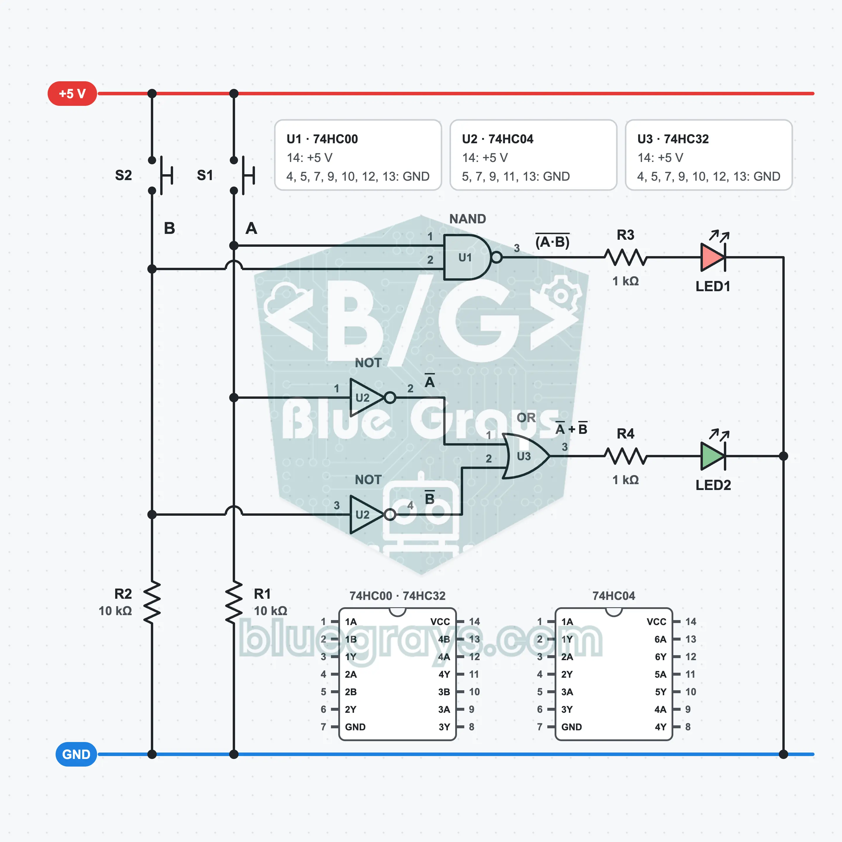
See De Morgan for Yourself: Two Circuits, the Same Table
Check De Morgan's law with your own eyes using two separate circuits. The same two buttons feed both circuits: one has a NAND from a 74HC00, the other has inversion with a 74HC04 and an OR from a 74HC32. The red and green LEDs blink together for all four input combinations, which means NOT (A · B) = NOT A + NOT B. In the task you build the second law too.
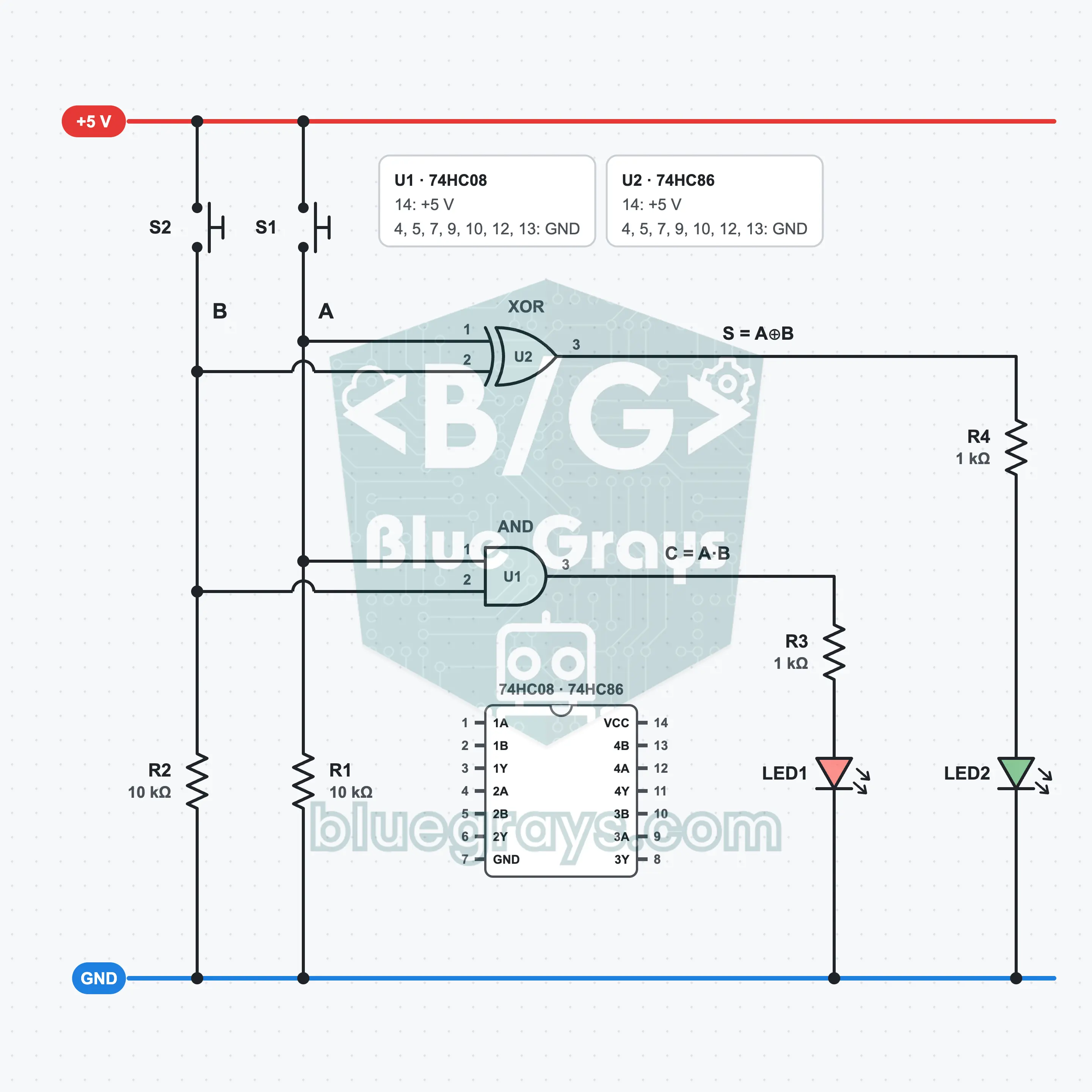
Half Adder
Build your first circuit that does arithmetic with two logic gates: the half adder adds two one-bit numbers. Two buttons are your numbers A and B; the 74HC86 (XOR) produces the sum bit and the 74HC08 (AND) the carry bit. The two LEDs are read side by side like a binary number: carry on the left, sum on the right. When you press both buttons together only the left LED lights, and you see the result 1 + 1 = 10 with your own eyes.
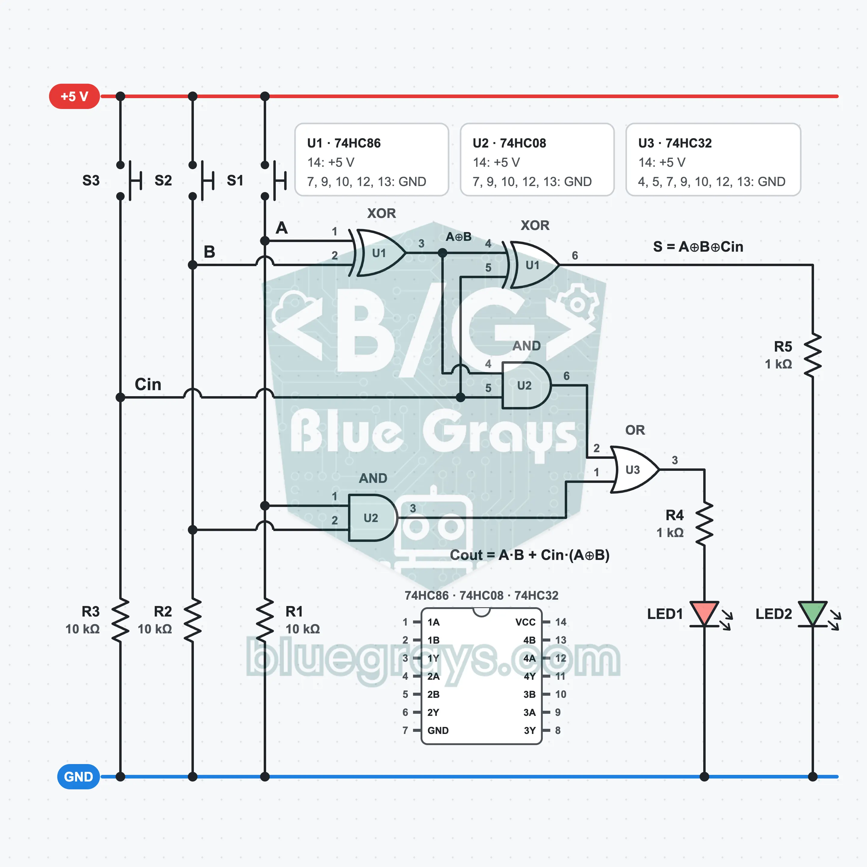
Full Adder
Go one step beyond the half adder: a full adder adds three bits at once. S1 and S2 are your numbers A and B; S3 is the carry from the digit on the right (Cin). The 74HC86, 74HC08 and 74HC32 produce the sum and carry bits together. Read the two LEDs side by side as a binary number: carry on the left, sum on the right. Press all three buttons together and both LEDs light, so you see 1 + 1 + 1 = 11 for yourself.
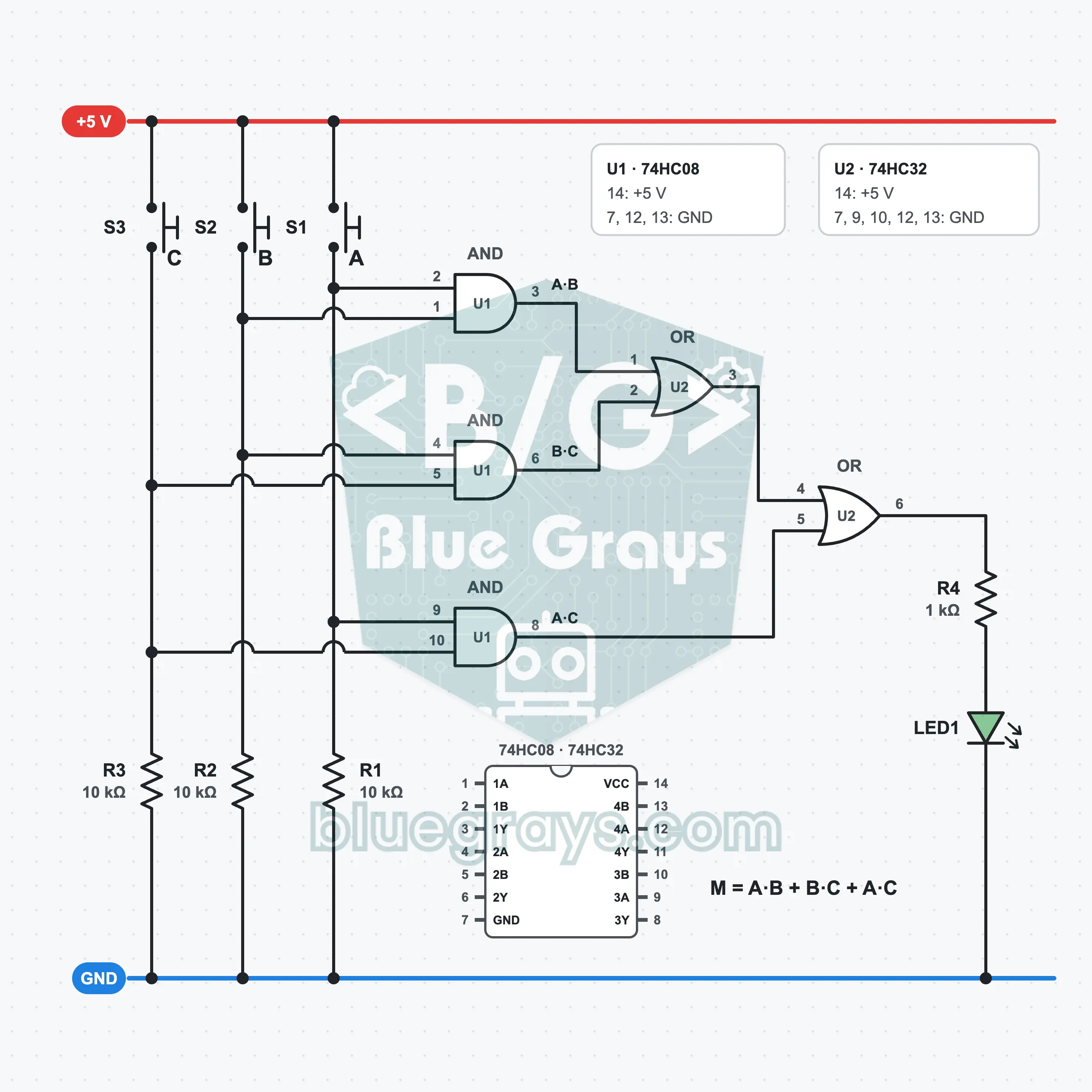
Majority Circuit: Three-Person Voting
Three people vote, and the green LED lights when at least two say yes. Three AND gates in the 74HC08 catch every pair of yes votes, and two OR gates in the 74HC32 add them together. You learn how to go from an eight-row truth table to a circuit: write down each row with a 1, then simplify and arrive at the expression M = A·B + B·C + A·C.
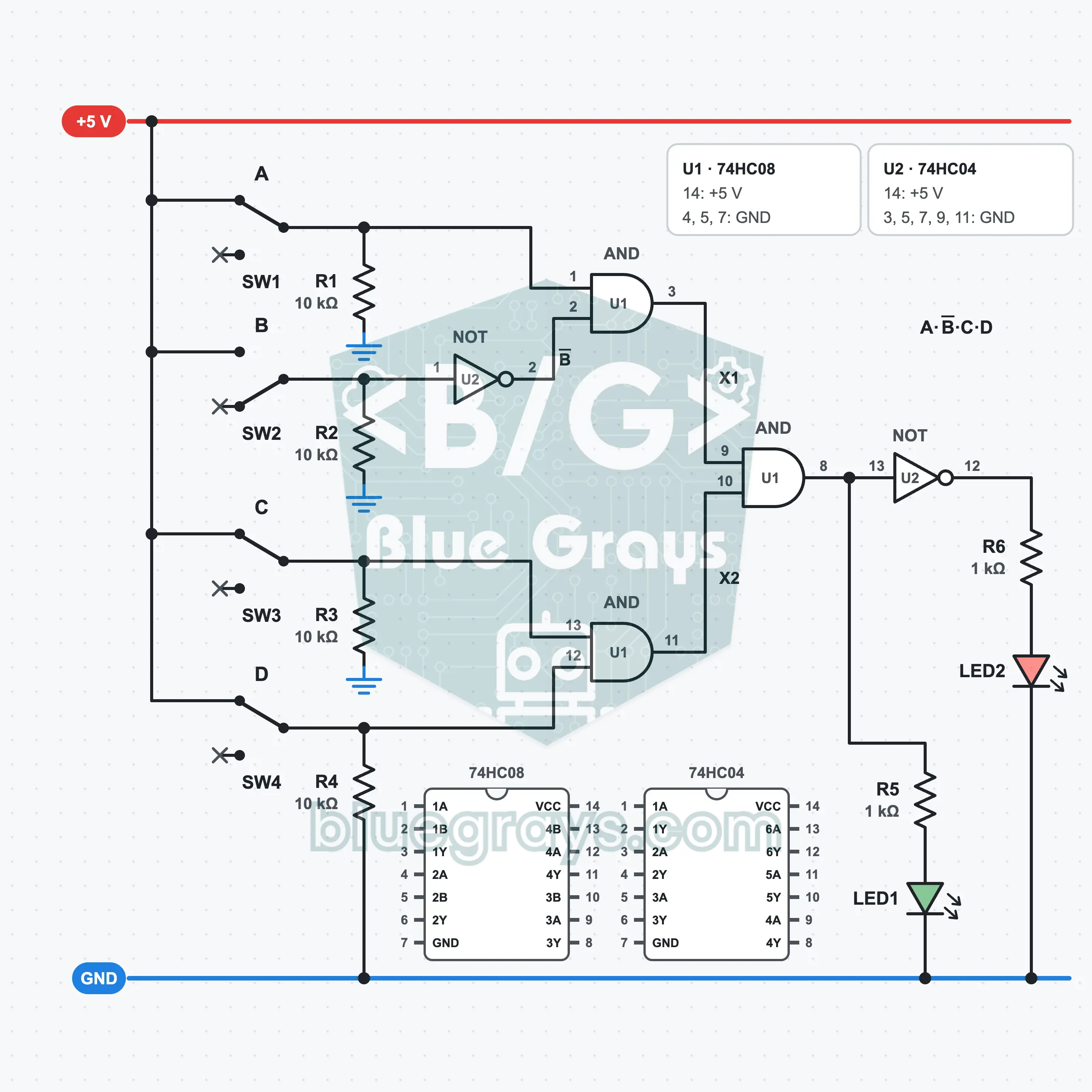
Combination Lock: A Code Circuit with Four Switches
Set a code with four slide switches: when the right combination (1-0-1-1) is entered, the green LED lights, and for the other 15 combinations the red LED does. The 74HC04 inverts the 0 in the code, and the 74HC08 ANDs the four bits in two stages. The red LED is the inverse of the lock output. In the task you also learn which NOT gate to plug in or remove to change the code.
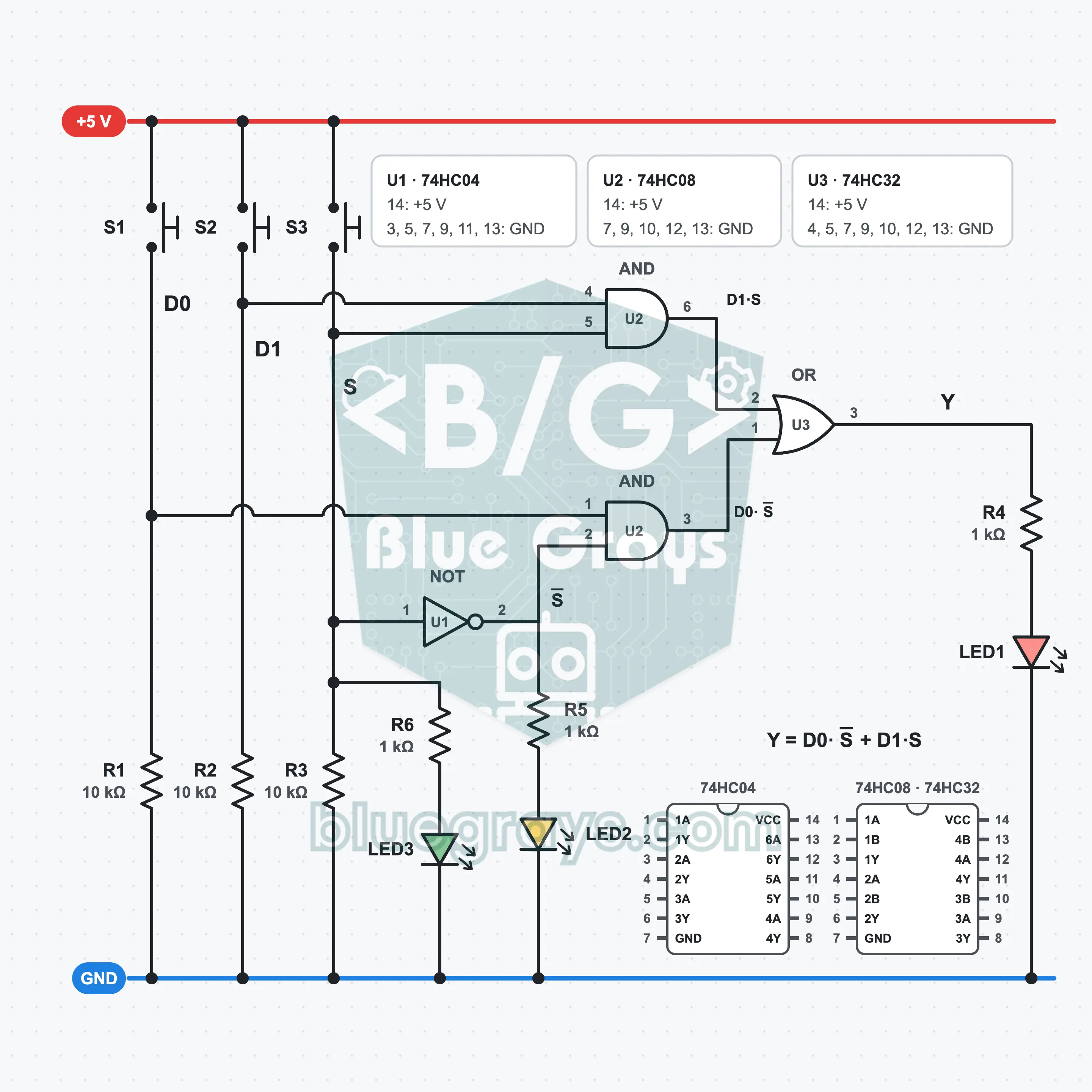
2-to-1 Multiplexer: Select One of Two Inputs
Let a single select input decide which of two data inputs reaches the output. In this 2-to-1 multiplexer, built with the 74HC04, 74HC08 and 74HC32, the red LED follows D0 while S3 is released and D1 while it is pressed. The yellow and green LEDs show which input is selected at that moment. This is the basis of circuits that choose one of two microphones or two sensors.
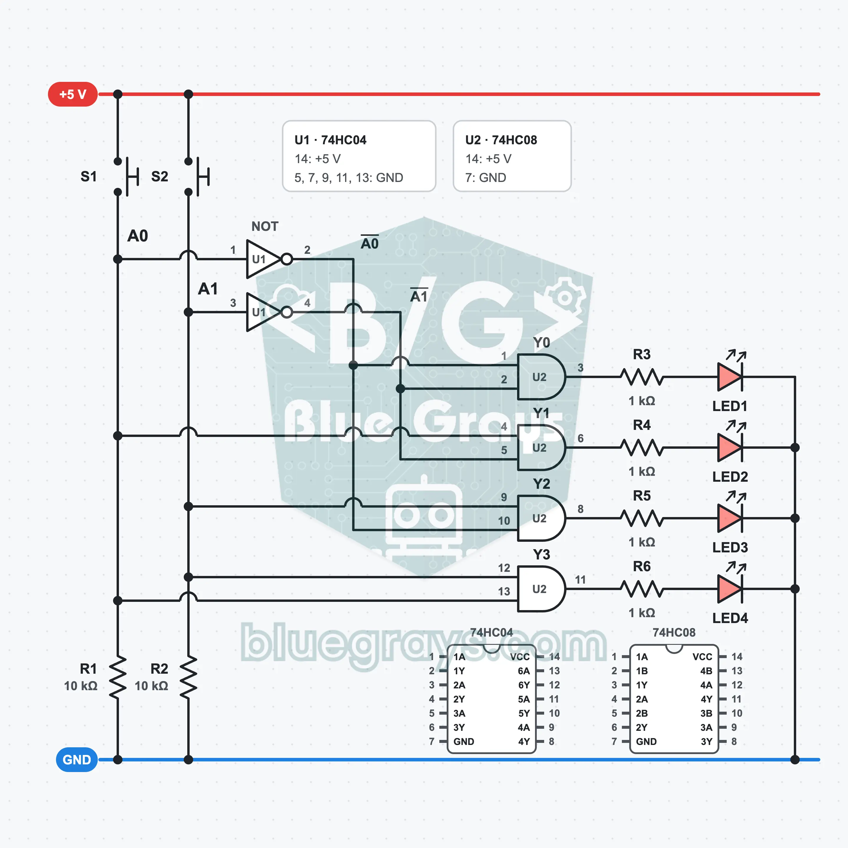
2-to-4 Decoder: Two Addresses, Four Outputs
Pick just one of four LEDs with two buttons. The 74HC04 inverts the two address inputs, and the four AND gates of the 74HC08 each open a separate output for one address: LED1 lights at 00, LED2 at 01, LED3 at 10, LED4 at 11. This address decoding method is the basis of how computers select the right memory cell and the right chip in a circuit.
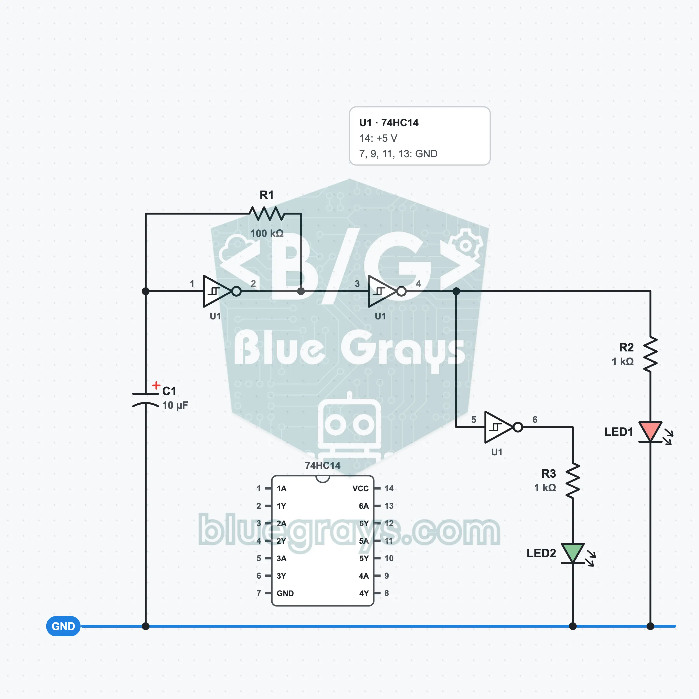
Gate Flasher: A Schmitt Oscillator with the 74HC14
Make your own clock signal with a single logic gate, one resistor and one capacitor. Thanks to its two separate thresholds, the Schmitt-trigger NOT gate inside the 74HC14 oscillates by itself as C1 charges and discharges; LED1 and LED2 blink in turn about once a second. You see hysteresis with your own eyes and learn why an ordinary NOT gate cannot do this job.
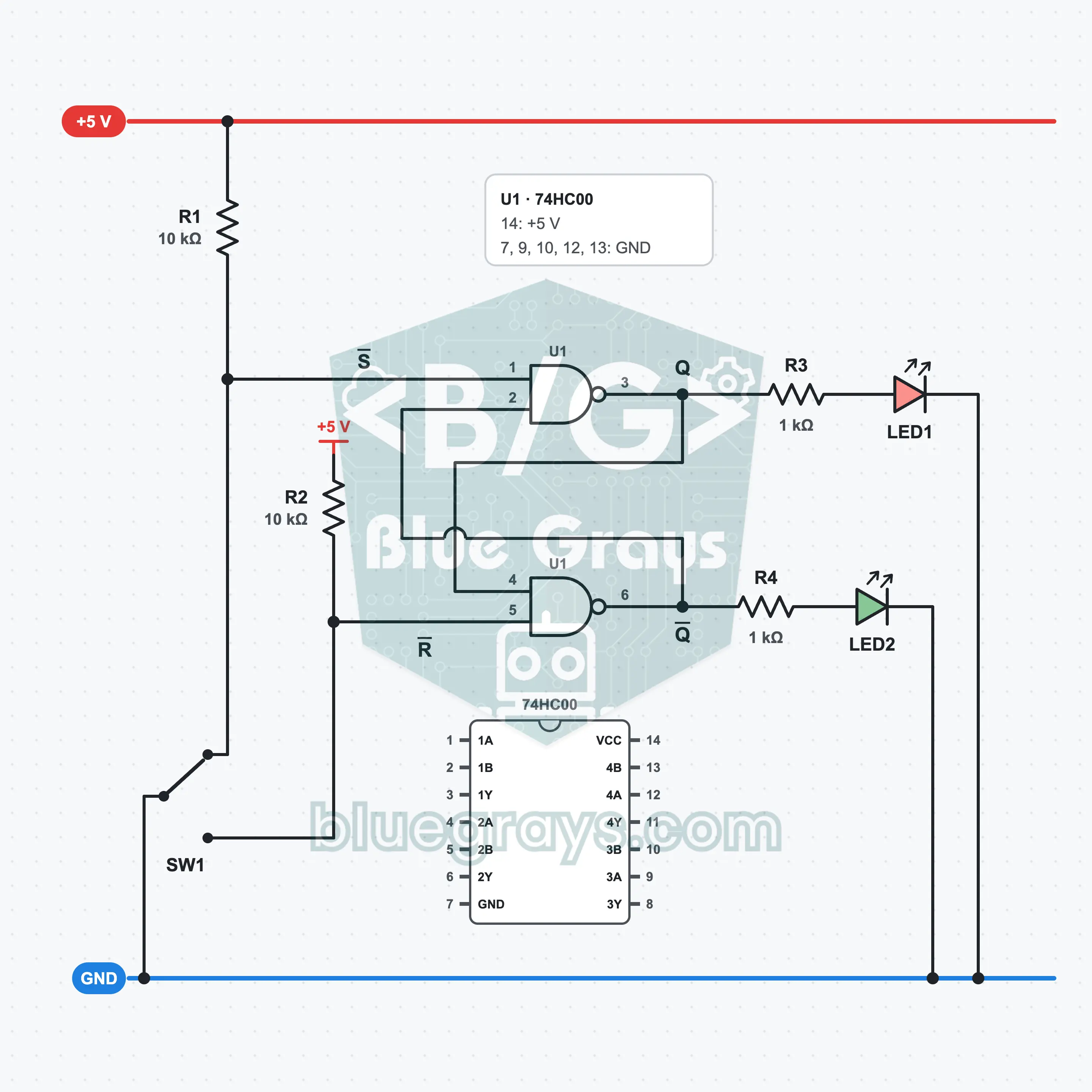
Switch Bounce Cleaner: A Debouncer with the 74HC00
When a switch closes, its contacts bounce several times within milliseconds, and a logic circuit thinks a single move is many pulses. This SR latch, built from two NAND gates of the 74HC00, changes once at the first touch of the SW1 slide switch and ignores the bounces after it. LED1 and LED2 show the clean output; you build the debounce logic yourself.
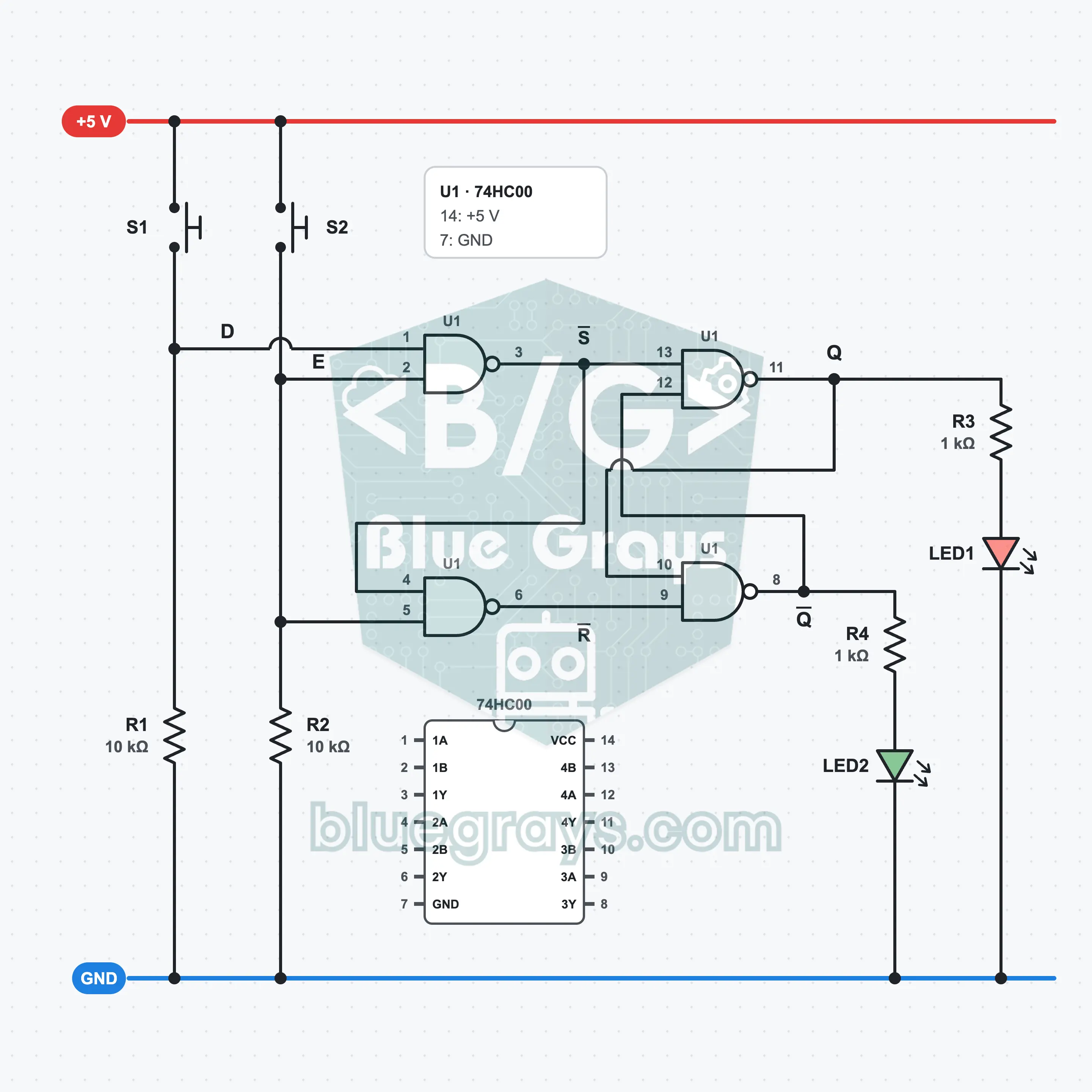
Gated D Latch: 1-Bit Memory with Four NAND Gates
Add a gate to a one-bit memory. The gated D latch you build from the four NAND gates of the 74HC00 sets the Q output equal to S1 (D) while S2 (E) is pressed, and keeps the last value when you let go of S2. LED1 shows Q and LED2 shows Q̄. One IC is enough, because one gate also works as an inverter at the same time. You see for yourself what level triggering means.
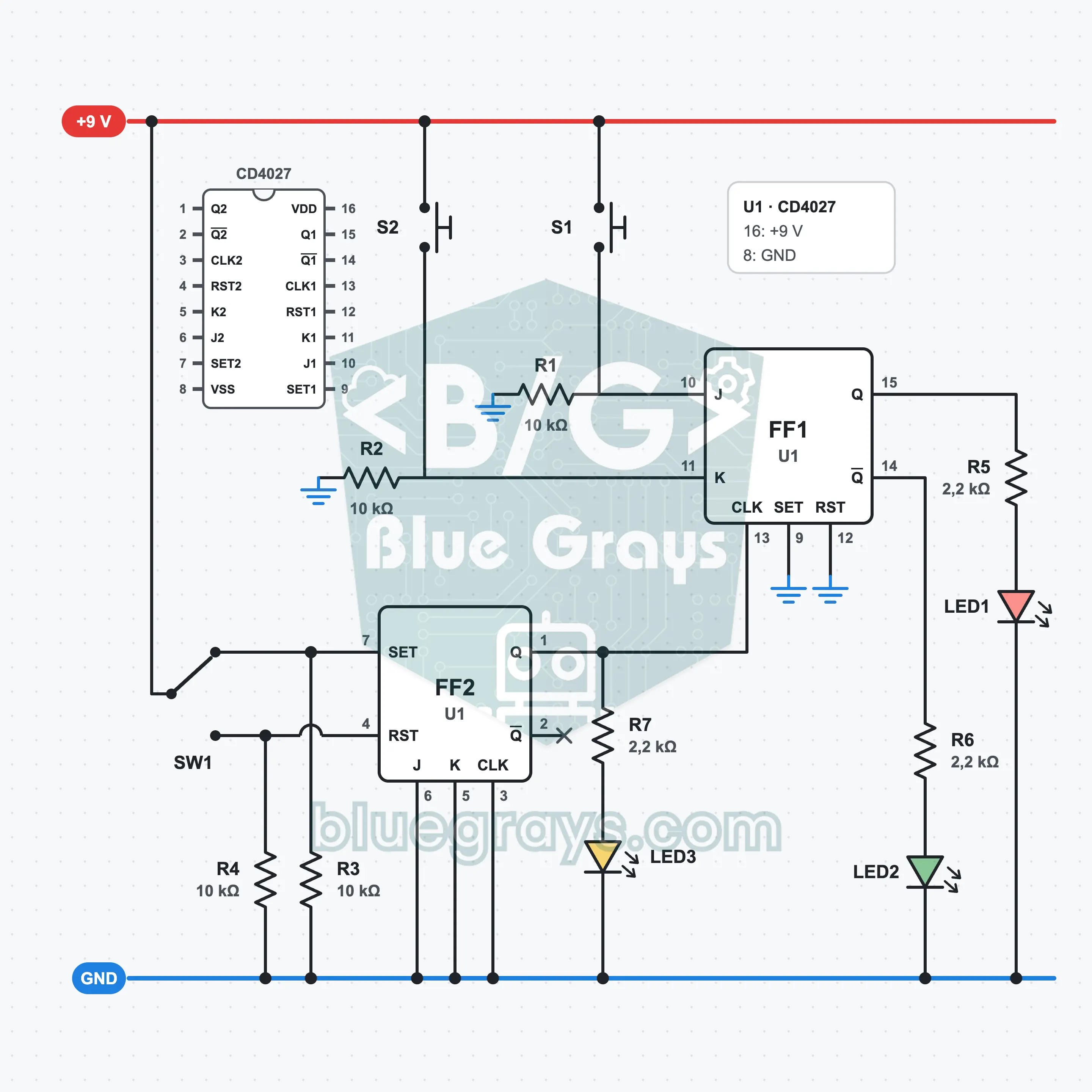
JK Flip-Flop: Four-Mode Memory with the CD4027
The JK flip-flop is the most capable member of the flip-flop family: with a single IC you try all of the hold, set, reset and toggle modes and read the truth table off the LEDs. In the circuit you build with the CD4027, you pick the mode with the J and K buttons and give the clock pulse with a slide switch. The yellow LED shows the clock, and the red LED shows the memory.
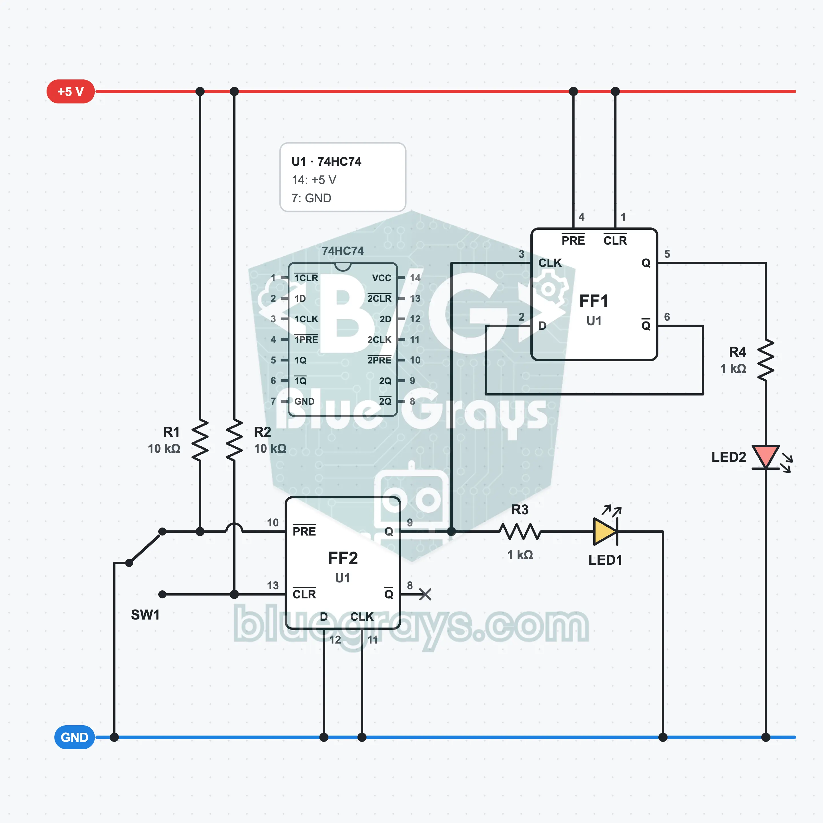
T Flip-Flop: Divide-by-Two Circuit with the 74HC74
Connect the output of a D flip-flop back to its own input and it becomes a T flip-flop: it changes state on every clock pulse. In the circuit you build with the 74HC74, the yellow LED shows the clock and the red LED shows the output, and the red one flashes at exactly half the speed. This divide-by-two stage is the first stage of every counter and digital clock.
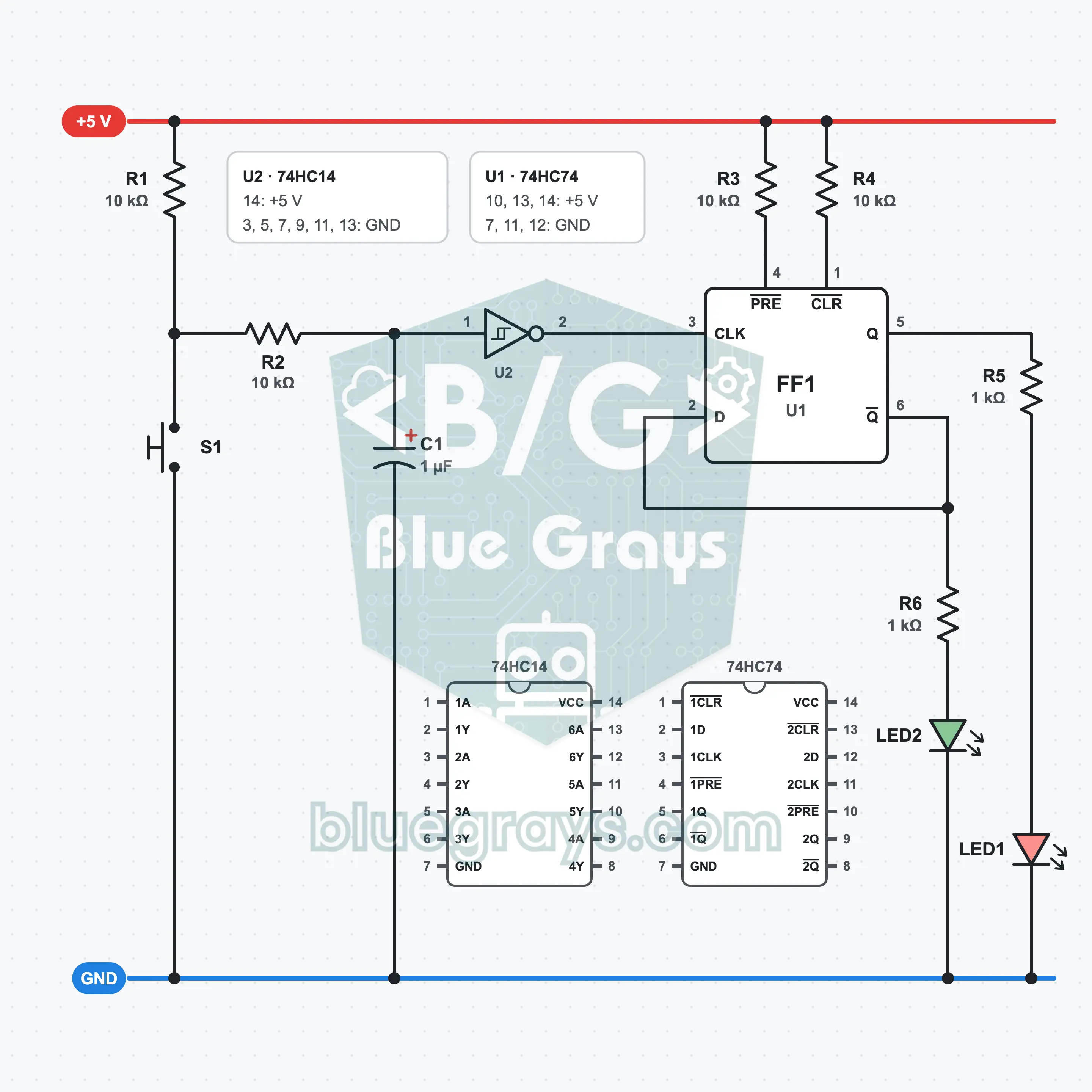
Toggle with a D Flip-Flop: A Debounced Single-Button Switch
Press the button once and the LED lights, press again and it goes out. When you connect the Q̄ output of the D flip-flop in the 74HC74 to its D input, it changes state on every clock pulse. S1 provides the clock pulse; the bounce of the button passes through an RC filter and the Schmitt gate of the 74HC14 and becomes a single clean edge. This way every press makes exactly one change.
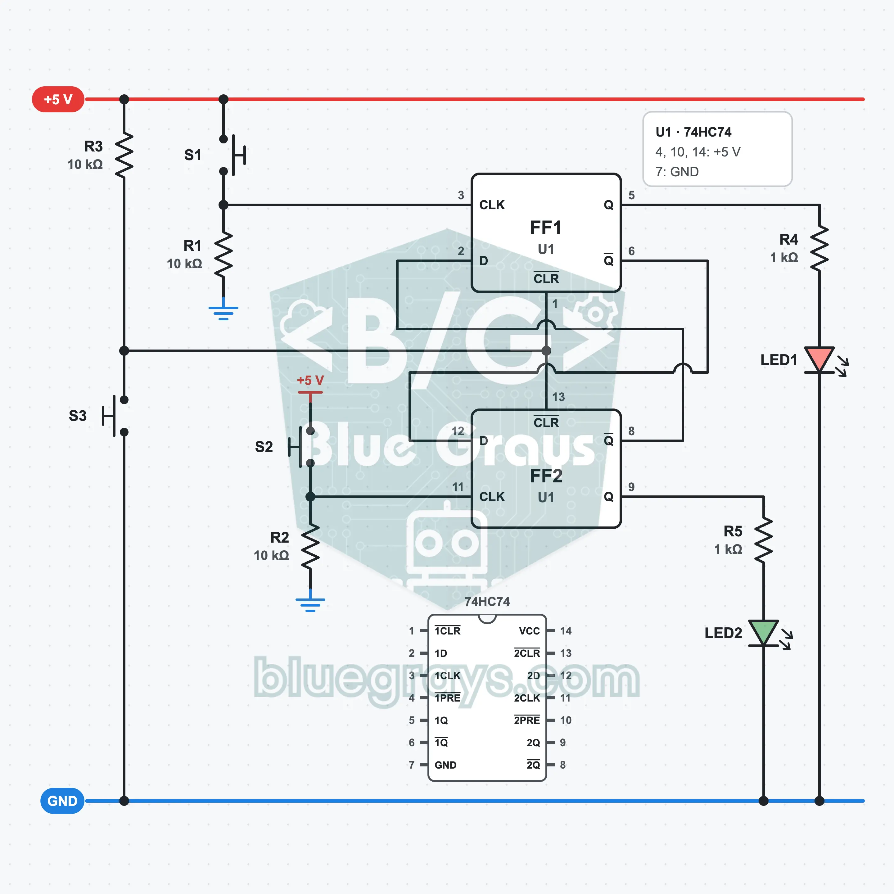
Who Pressed First? A Quiz Buzzer Circuit: Lockout with the 74HC74
Two contestants, two buttons: the LED of whoever presses first lights and locks, and it makes no difference how much the latecomer presses. The two D flip-flops in the 74HC74 hold each other's D input. The S3 reset button puts both out and a new round begins. Button bounce does not spoil the result, because every extra edge reloads the same value.
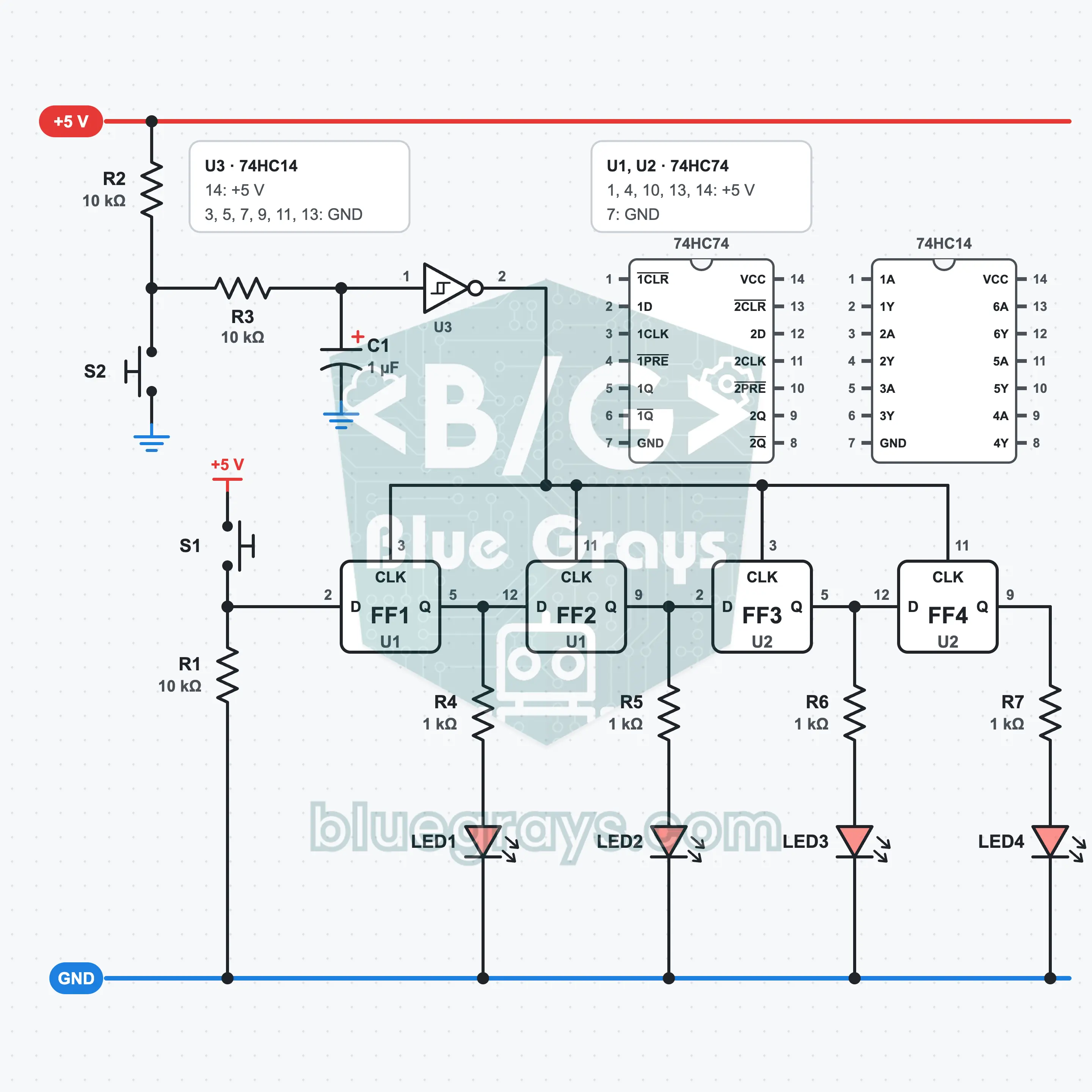
4-Bit Shift Register: Shift Bits with the 74HC74
Pick a bit with S1, press S2: the bit enters LED1 and the earlier bits shift one step to the right. The four D flip-flops in two 74HC74s are connected like a chain: each Q goes to the D input of the next. The clock pulse comes from the debounced S2 button via a 74HC14. Four bits entering on a single wire, serial, appear on four LEDs in parallel.
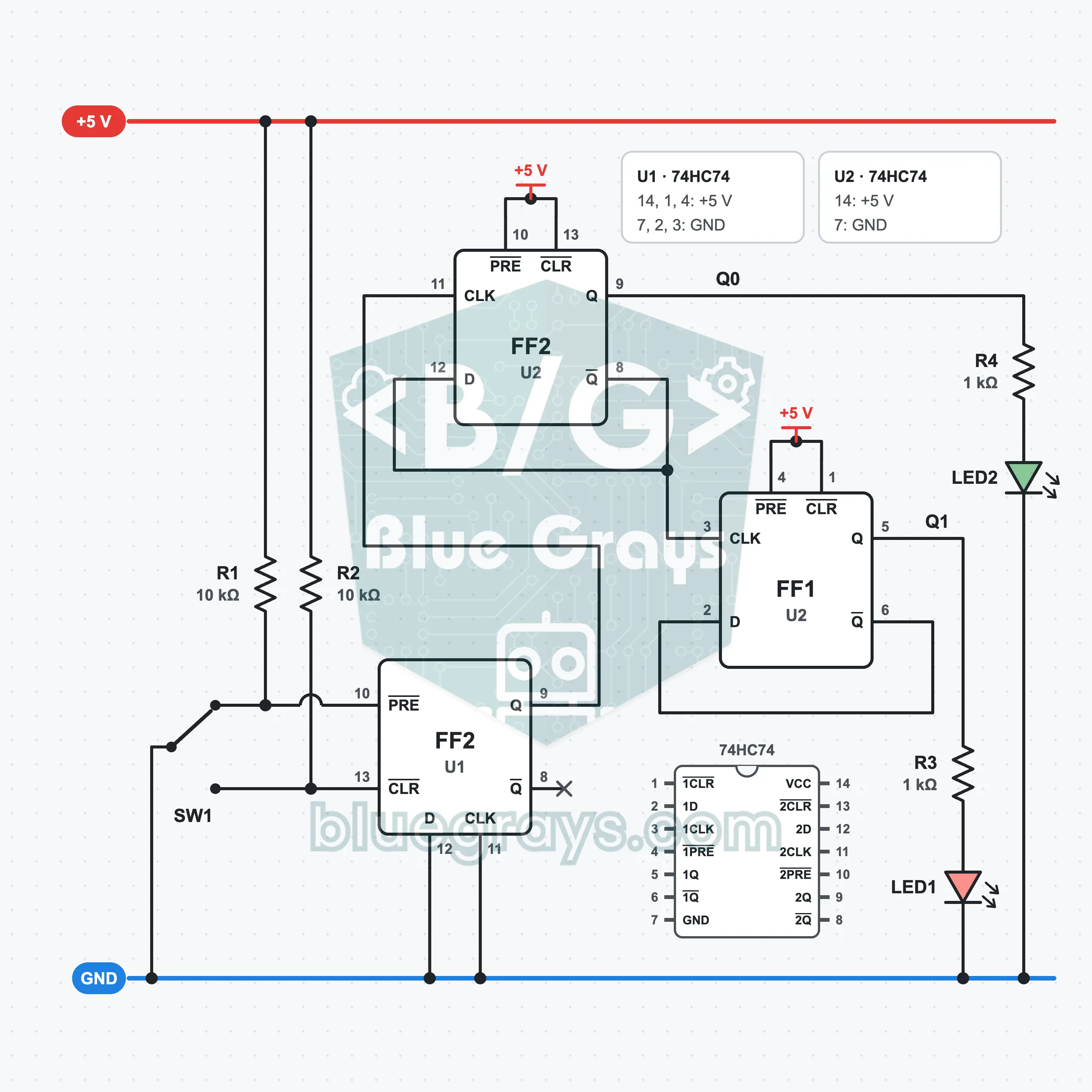
2-Bit Counter: Count from 0 to 3 with the 74HC74
Connect two flip-flops in a chain to build a counter that counts from 0 to 3. In this 74HC74 circuit, each slide of the switch to the 1 position gives a pulse: the green LED shows the 1s place and the red LED the 2s place, so the count goes 00, 01, 10, 11 and starts again. This asynchronous (ripple) counter is a basic building block of digital clocks and frequency dividers.
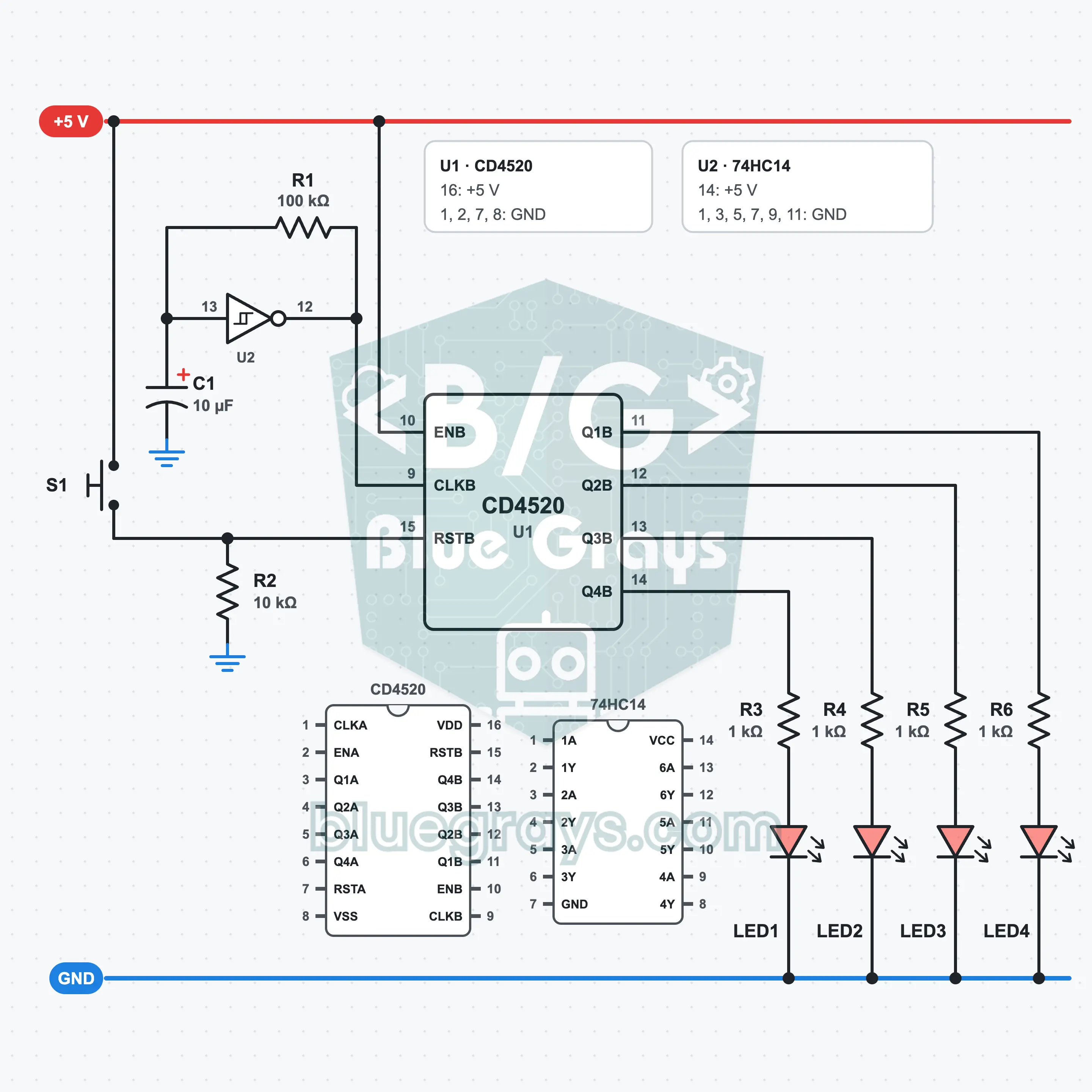
4-Bit Binary Counter: A Circuit That Counts from 0 to 15 with the CD4520
Four LEDs count in binary from 0 to 15: LED1 on the left is the 8s place and LED4 on the right is the 1s place. The four flip-flops inside the CD4520 (U1) run on the same clock, so it is a synchronous counter. The clock comes from an oscillator of about 1 Hz built with a 74HC14 (U2). After 15 the counter overflows and returns to 0. Press S1 and the four LEDs go out and counting restarts from 0.
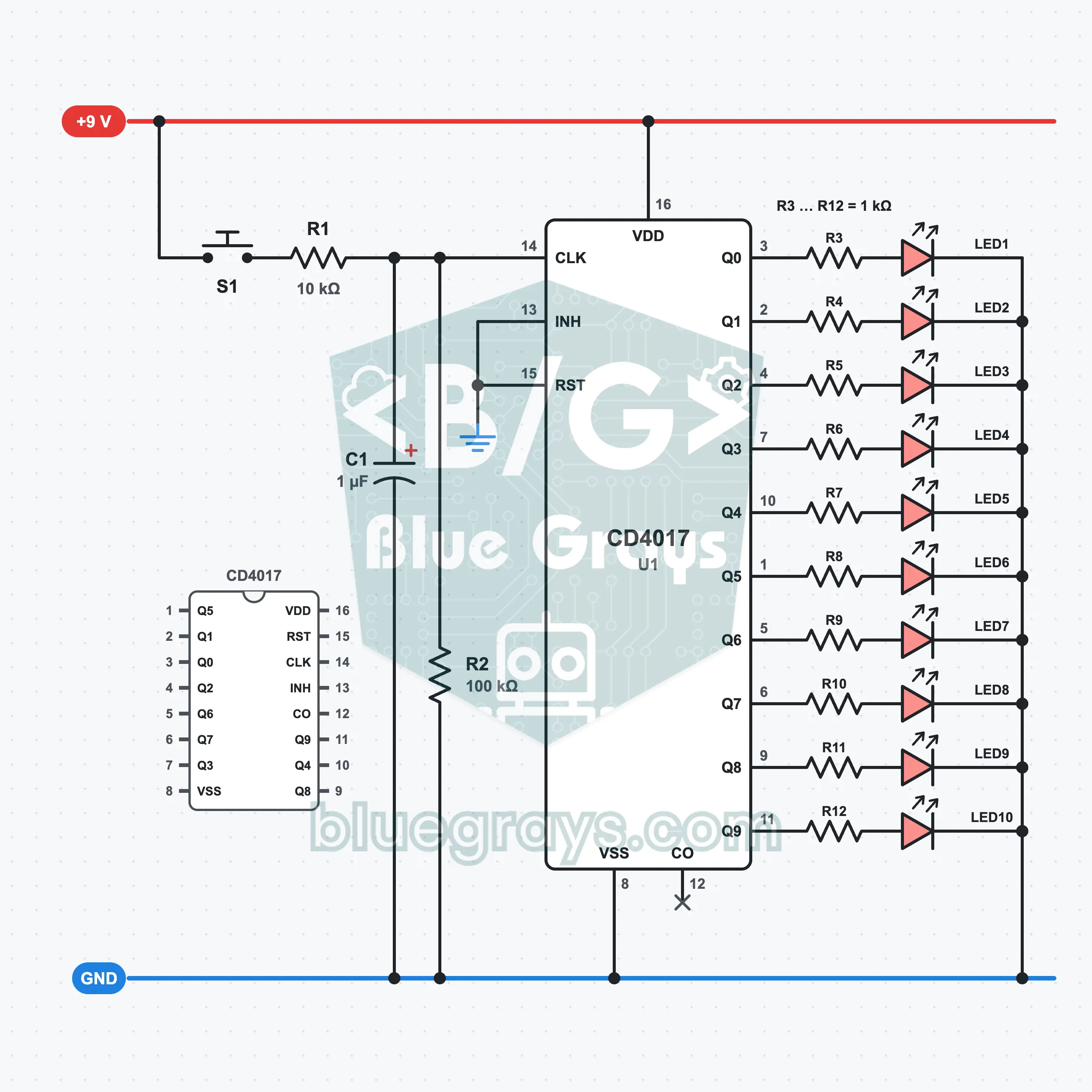
4017 Running Light: 10 LEDs Stepped by a Button
Make the light jump to the next LED every time you press the button. The CD4017 decade counter counts the incoming clock pulses and lights only one of its ten outputs; after the tenth pulse it goes back to the start. A small resistor and capacitor filter cleans up the bounce of the button. You learn counter logic, the basis of running light effects and the clock pulse concept.
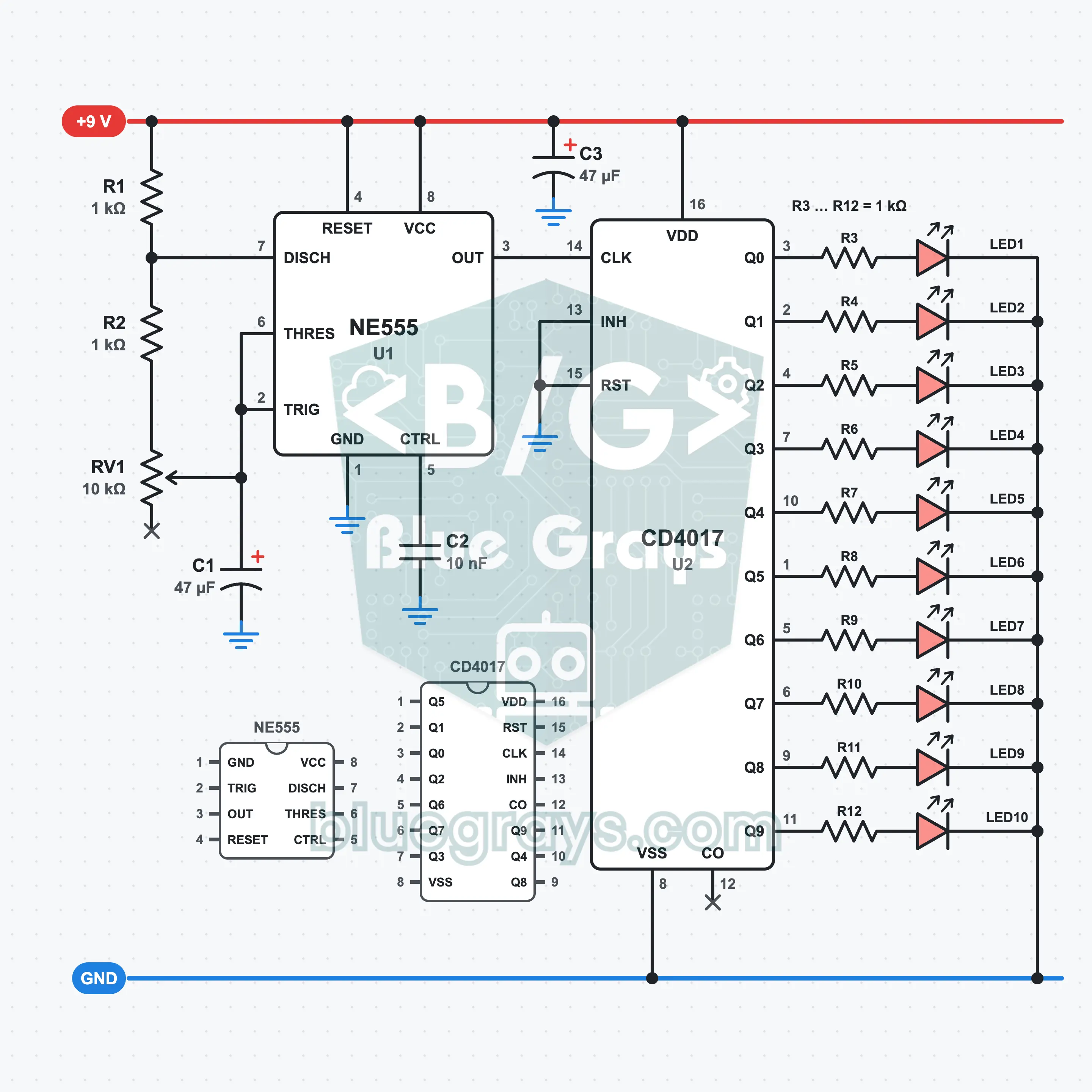
555 and 4017 Running Light: 10 LEDs with Adjustable Speed
Free the running light from the button: the NE555 produces the clock pulses itself, and the CD4017 counts these pulses and lights ten LEDs one after another. You set the speed with a potentiometer; the light completes one lap in about 1 second at the fastest setting and in 7.5 seconds at the slowest. You learn how to link two ICs with a clock line, how to change the frequency of an oscillator with a resistance and what a supply capacitor is for.
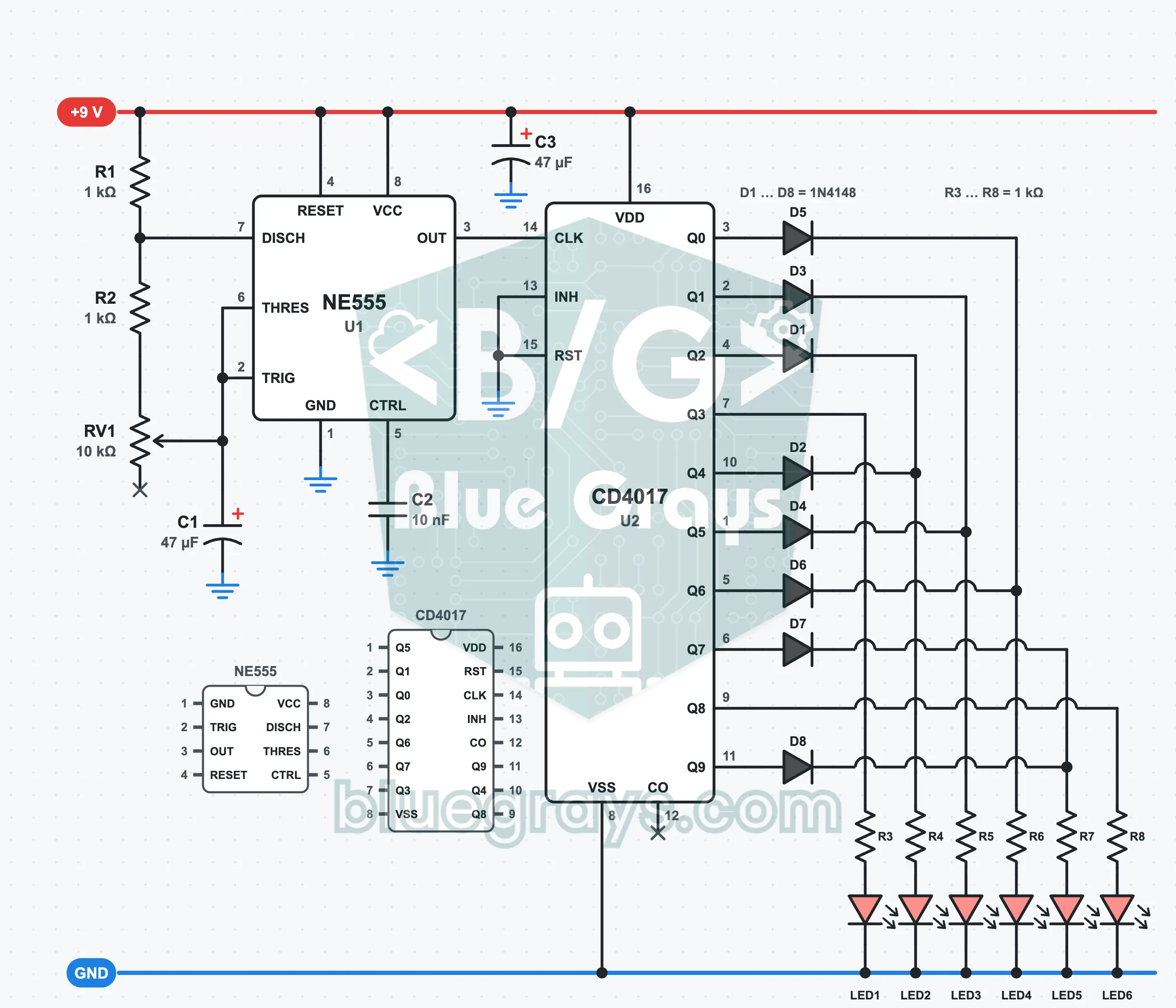
Back-and-Forth LED Scanner: A Sweeping Light with the 555 and 4017
On six LEDs, a light runs to one end and, once it gets there, turns around and comes back: a sweeping scanner light effect. The NE555 (U1) produces the clock pulses, the CD4017 (U2) counts ten steps and eight 1N4148 diodes (D1 to D8) spread those ten steps over six LEDs as a trip out and back. You set the speed with the RV1 potentiometer. You learn about the diode OR connection and how much current a CD4017 output can supply.
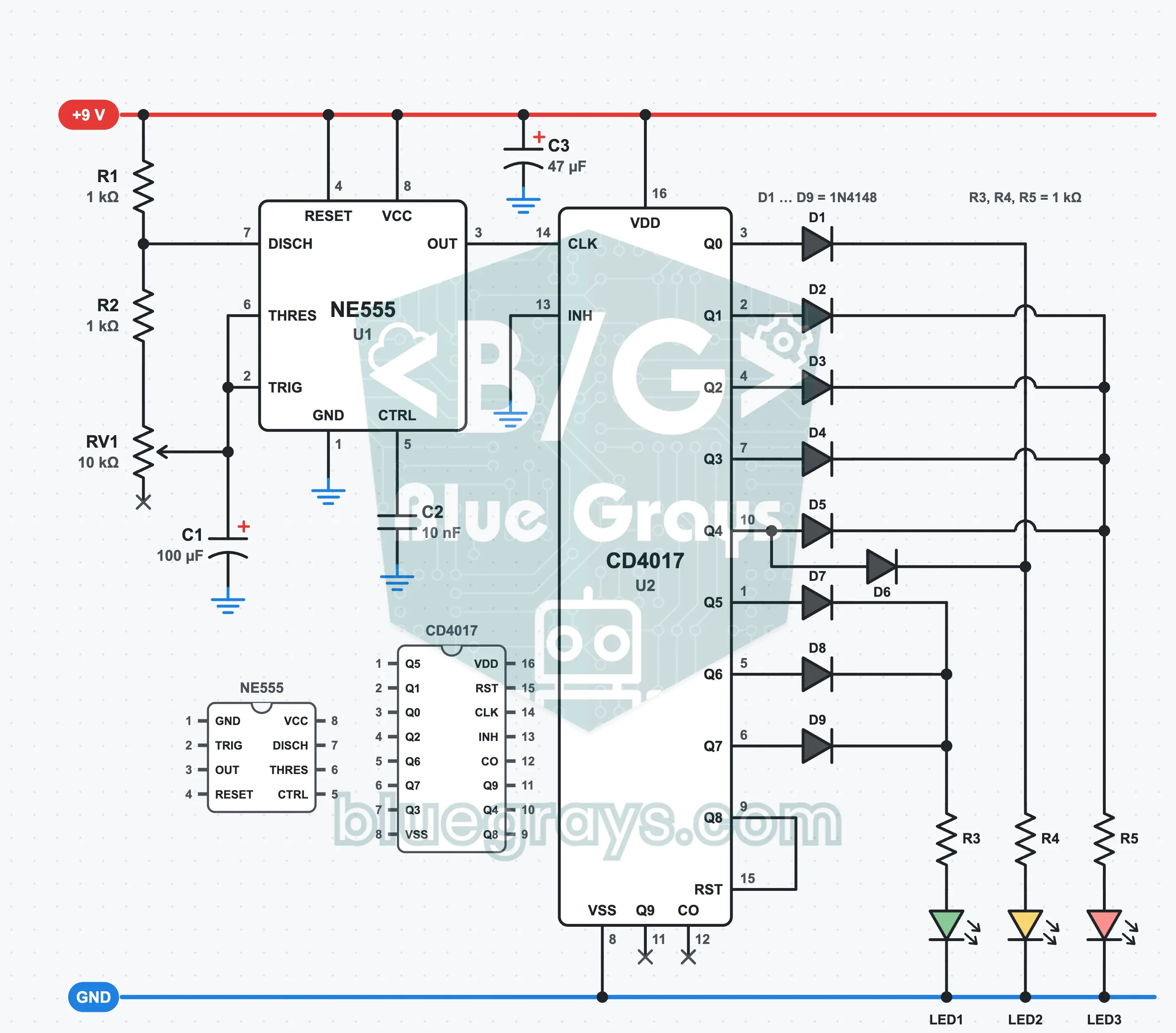
Traffic Light: Red, Yellow, Green with the 555 and 4017
Red, red with yellow, green and yellow: the traffic light sequence on your desk with three LEDs. The NE555 (U1) produces the step pulses, the CD4017 (U2) counts and nine 1N4148 diodes (D1 to D9) spread the steps over the colors: red 4 steps, green 3, yellow 1. Because Q8 is connected to reset, the cycle closes after 8 steps. You set the times with RV1. This is a learning circuit, not a real traffic light.
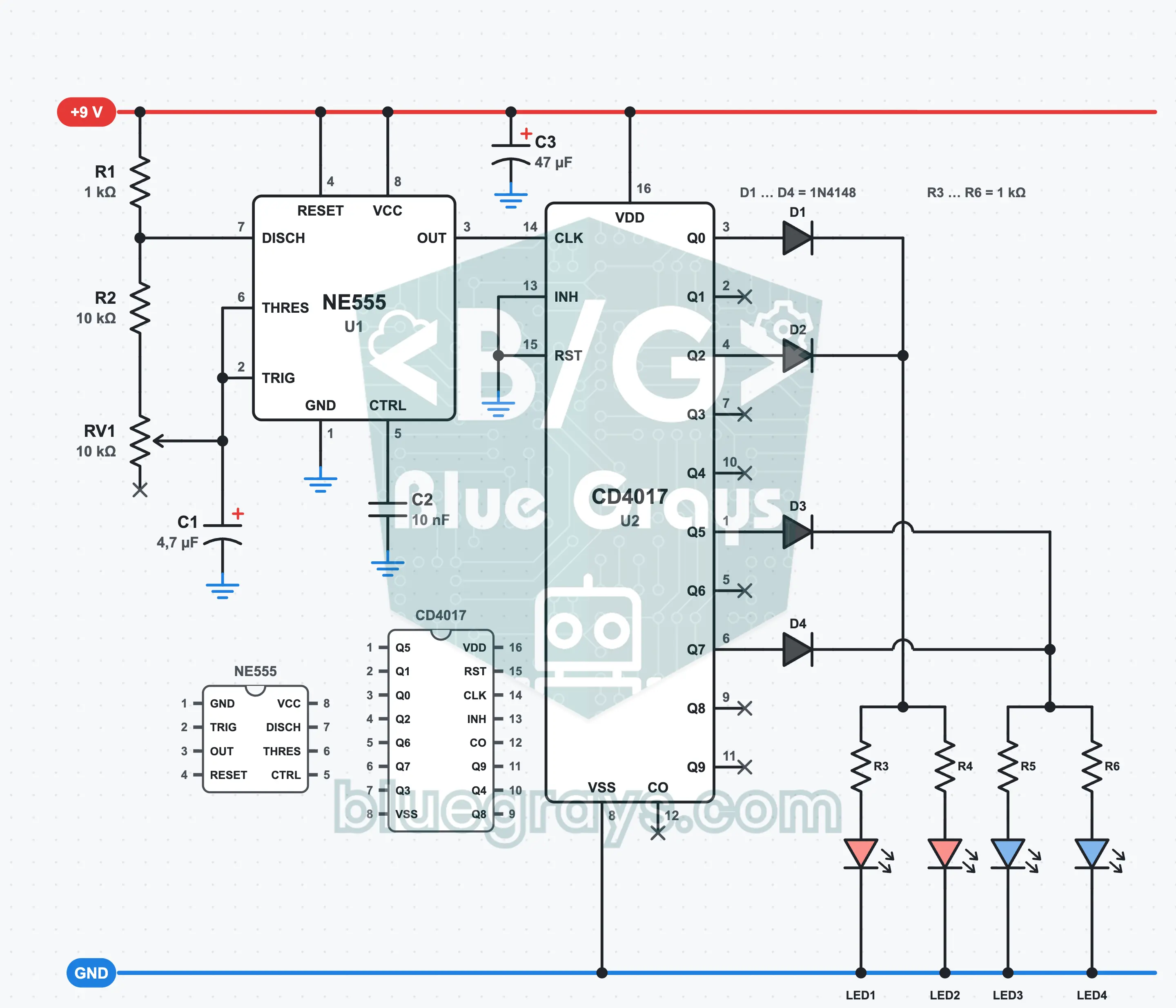
Police Light Bar: Red and Blue Double Flash with the 555 and 4017
The red LEDs flash twice, then the blues flash twice, like the roof light of a toy patrol car. The NE555 (U1) produces 7 to 15 pulses a second, the CD4017 (U2) counts ten steps and four 1N4148 diodes (D1 to D4) spread four steps over two colors. You set the speed with RV1. You learn about OR with diodes, the forward voltage of a blue LED and the current limit of a CD4017 output. For toys and models only.
Electronic Dice: Six-LED Dice with the 555 and 4017
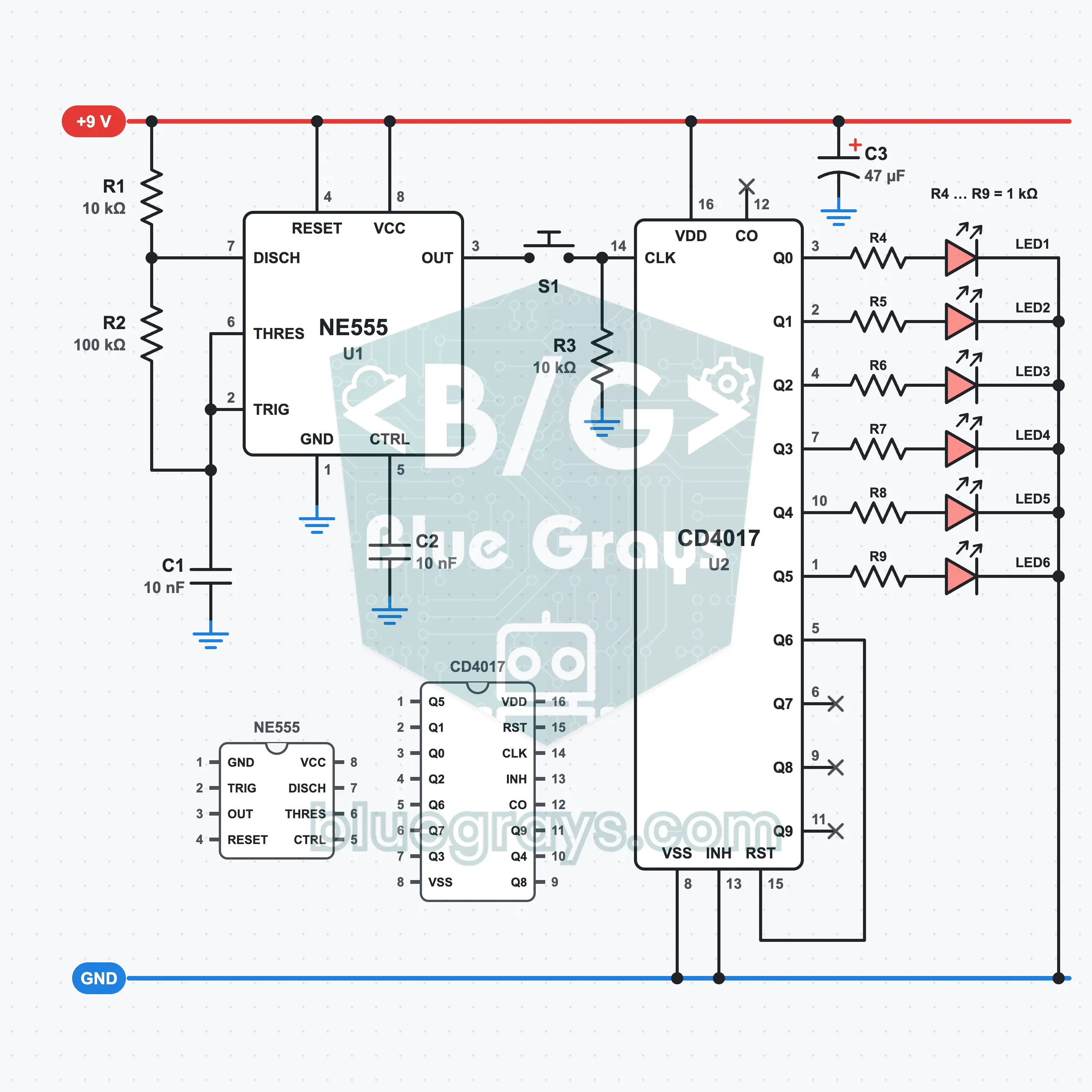
Press the button and all six LEDs glow at once; release it and only one stays lit. Its position from the left is your roll. The NE555 produces about 686 pulses a second, and with them the CD4017 counts from 1 to 6 and starts over. The count goes round so fast that you cannot control where it stops; that makes the result random. You learn how to reset a counter at any number you like, how to switch the clock line on and off with a button, and what a pull-down resistor is.
0 to 9 Counter: 7-Segment Display with the 555 and CD4026
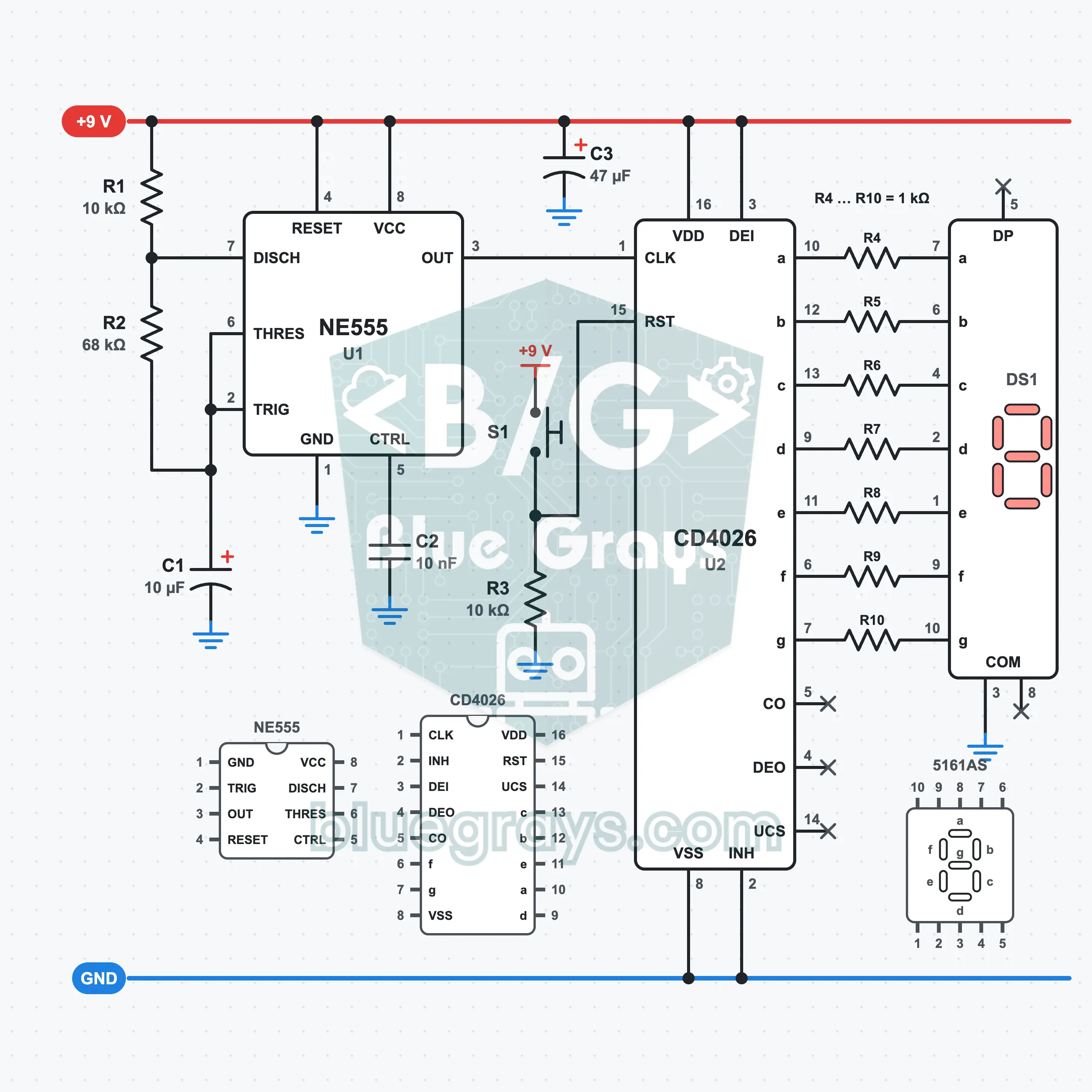
The single-digit display goes up once a second: 0, 1, 2 and so on up to 9, then back to 0. The NE555 produces a clock pulse of about 1 Hz, and the CD4026 counts these pulses and decides by itself which segments light for which digit; no separate decoder is needed in between. Press the button and the count returns to 0. You learn about the common cathode 7-segment display, why every segment needs its own resistor, and the reset input of a counter.
Push-Button Scoreboard: A Number That Goes Up with Each Press with the CD4026
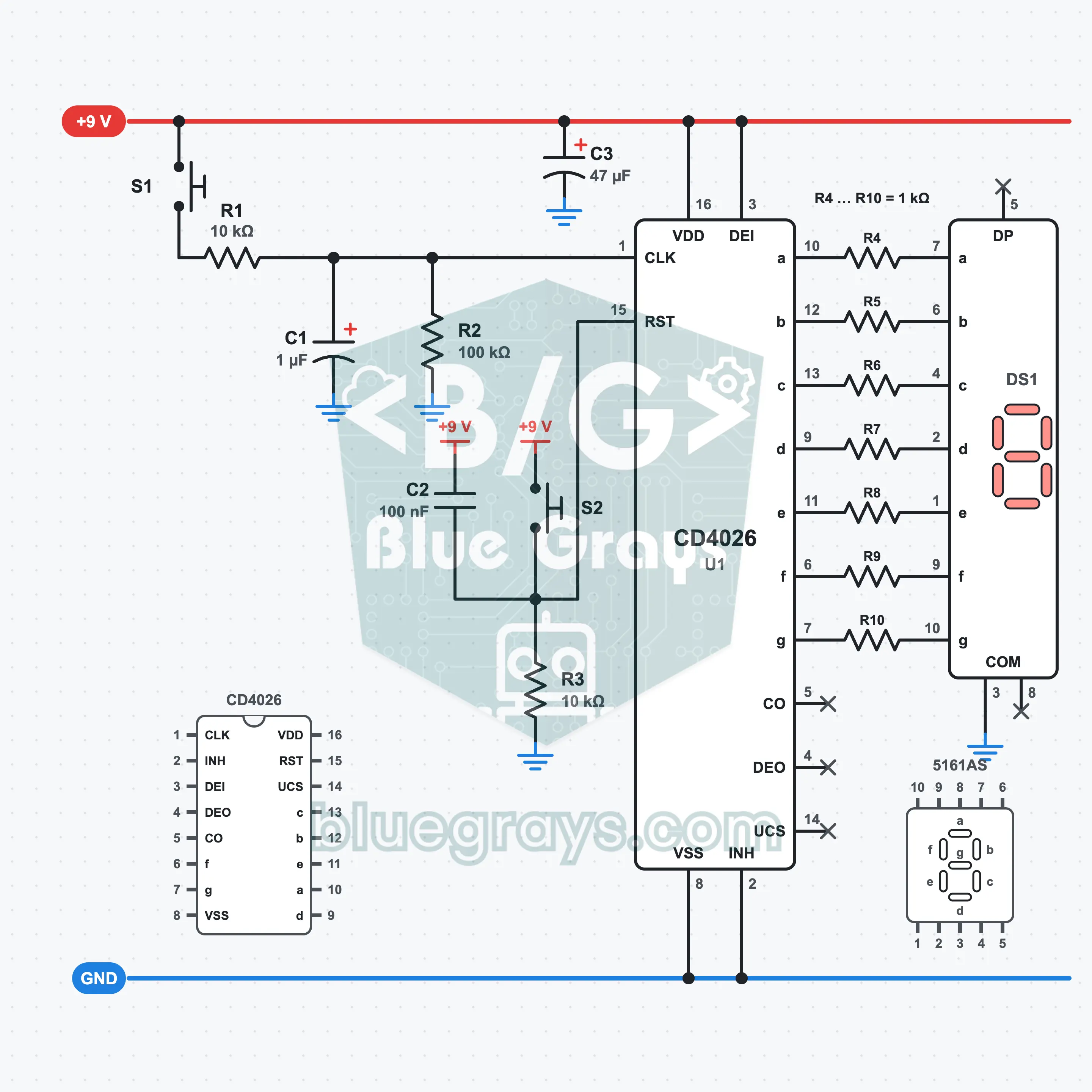
Each time you press S1, the single-digit display goes up by one: 0, 1, 2 up to 9, then back to 0. The CD4026 counts the presses and drives the digit on a common cathode 7-segment display by itself. Because the button contact bounces as it closes, one press could skip several numbers; an RC filter and the Schmitt input of the IC prevent this. S2 resets the score to 0.
Precision Dark Switch
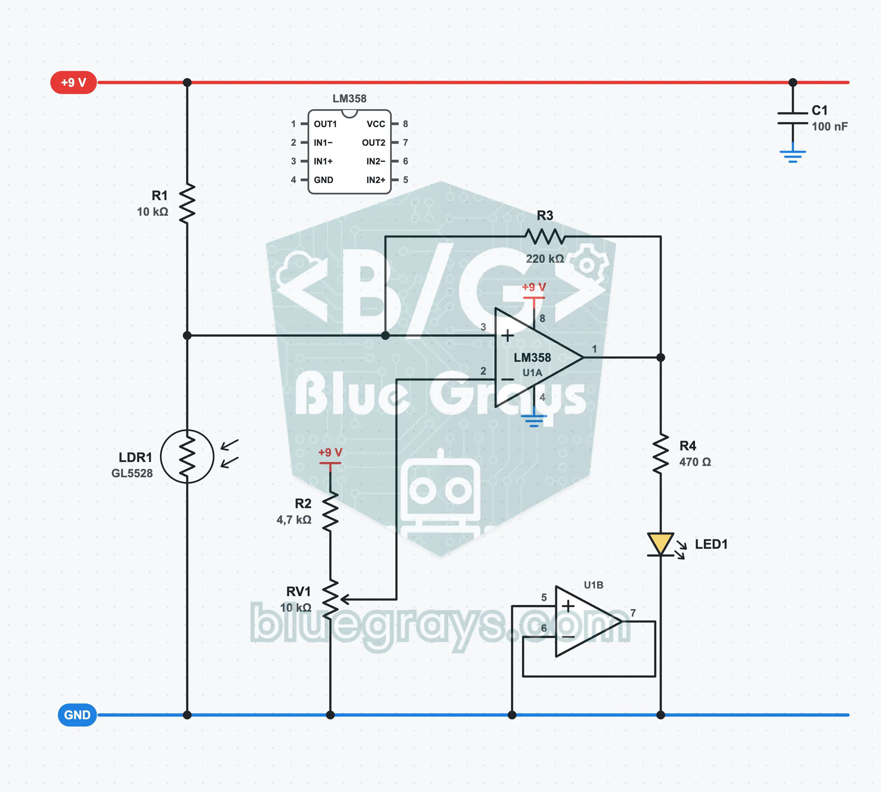
When the room gets dark, the yellow LED lights by itself, and when it gets bright again it goes out. The LDR turns light into a voltage, and the LM358 compares this voltage with a threshold you set with the pot. A 220 kΩ resistor fed back from the output adds hysteresis: the LED lights at about 9.3 lux and goes out at 10.5 lux, so it does not flicker even when the light changes slowly. You learn about the comparator, hysteresis and the lux calculation.
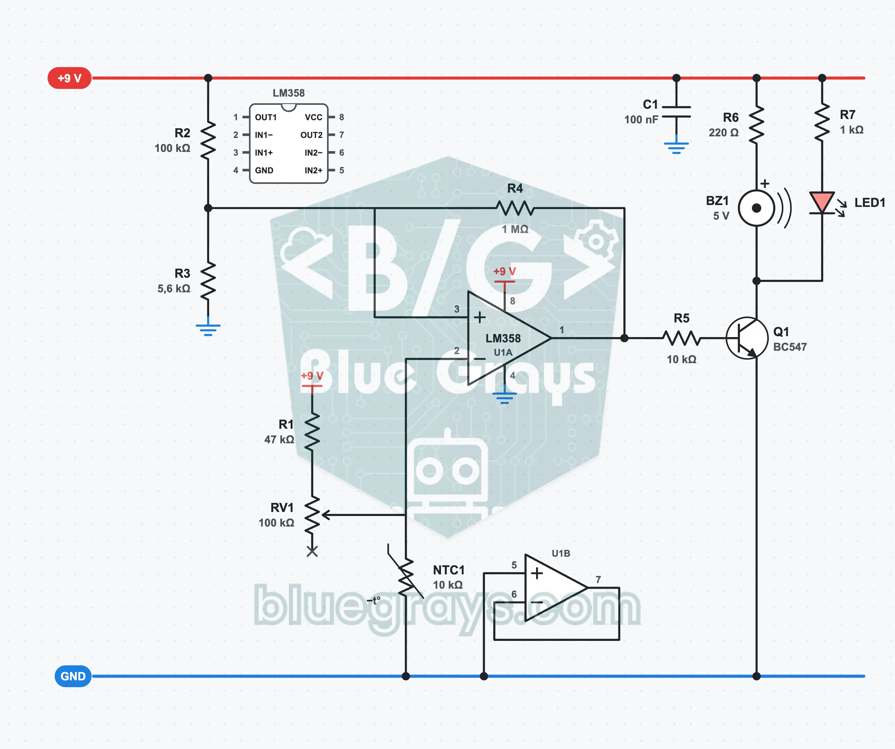
Op-Amp Temperature Alarm: LM358 and NTC
A temperature alarm that sounds when the surroundings heat up. A bridge made of NTC1, RV1 and three resistors feeds voltages to the two inputs of the LM358; when the NTC heats up and passes the threshold, the output turns on the buzzer and the LED through Q1. You set the threshold with RV1 between about 30 and 59 °C, and R4 adds about 2 °C of hysteresis. Thanks to the bridge, the threshold does not drift even when the battery weakens.
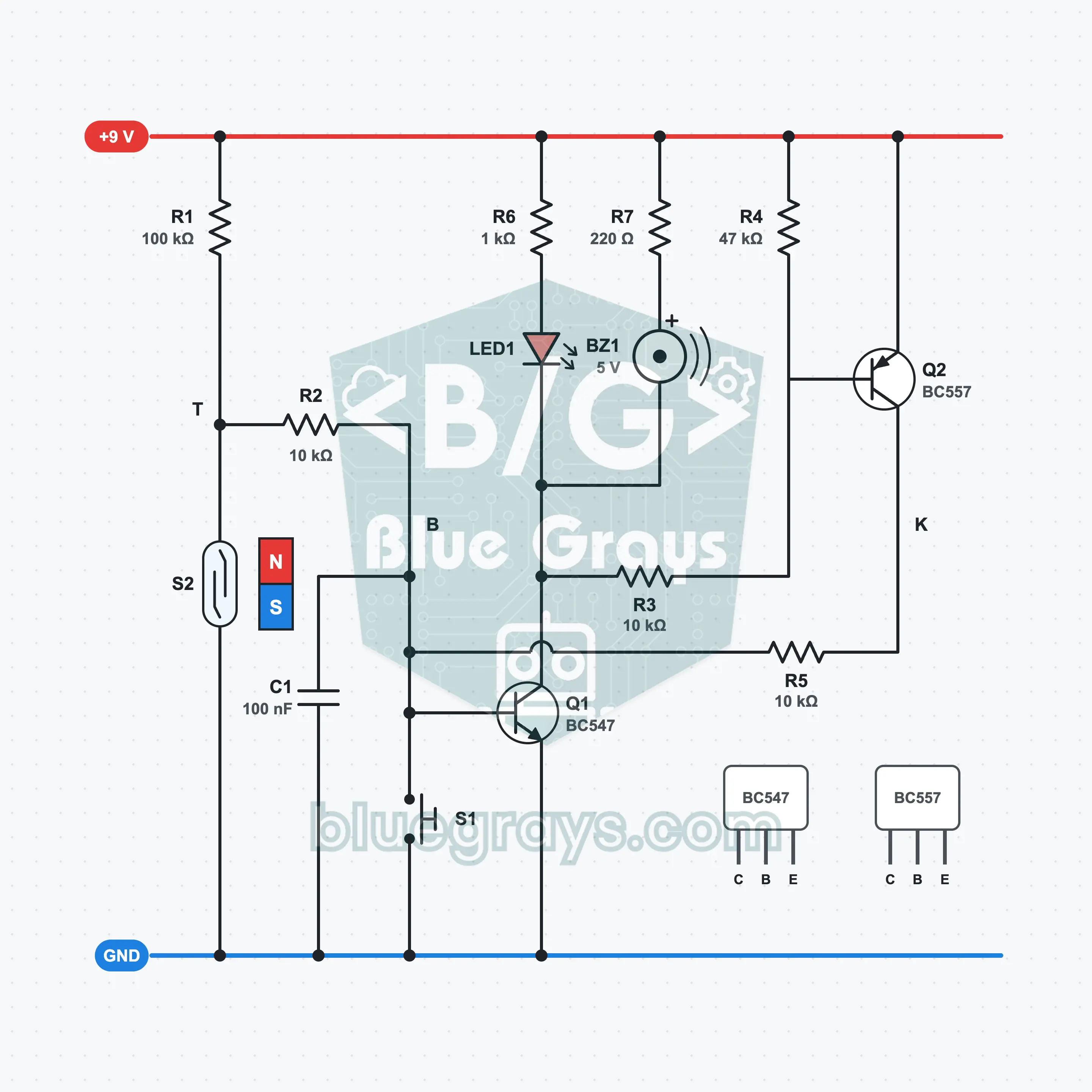
Magnetic Door Alarm: A Latching Alarm with a Reed Switch
Put a reed switch (S2) on the frame and a magnet on the door: the moment the door opens, the buzzer sounds and the LED lights. Closing the door again does not silence the alarm; only the reset button (S1) does. A BC547 (Q1) and a BC557 (Q2) hold each other on and latch like a thyristor. While waiting, it draws only about 0.09 mA from the battery.
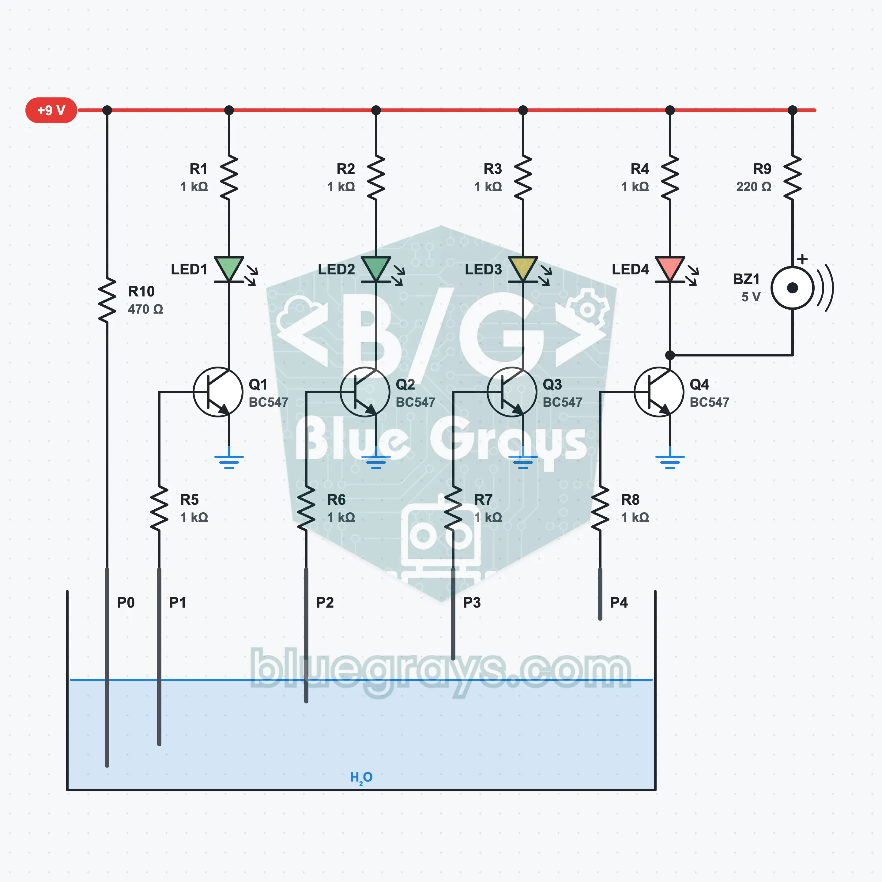
Water Level Indicator (4 Levels)
A level indicator that shows the height of the water in a glass with four LEDs. Five wires hang into the water: one is common, four sit at different heights. When the water reaches a wire, that wire's BC547 transistor turns on and its LED lights: first two green, then yellow, and red at the top. Along with the red LED the active buzzer sounds too and tells you the container is full. You try out how tank gauges work, the conductivity of water and switching with a transistor.
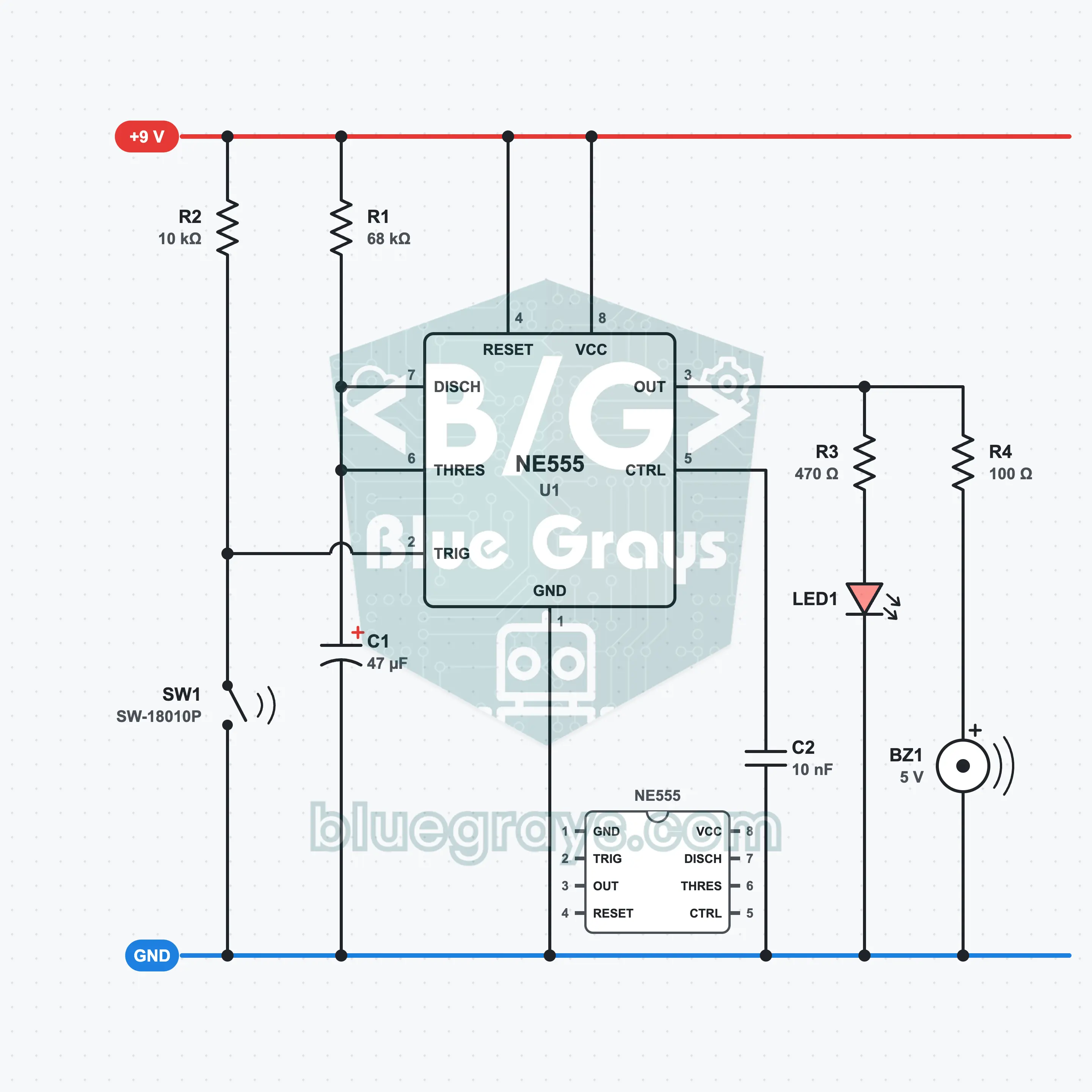
Earthquake Alarm: A Circuit That Sounds When Shaken
Tap the table lightly: the buzzer sounds, the LED lights and after about 3.5 seconds the circuit goes silent by itself. A vibration sensor with a thin spring inside picks up the shaking; an NE555 in one-shot (monostable) mode holds the time. The sensor's contact lasts only the blink of an eye, and the 555 stretches it into a warning that lasts seconds. This is not an earthquake warning system; it is an educational circuit that announces shaking.
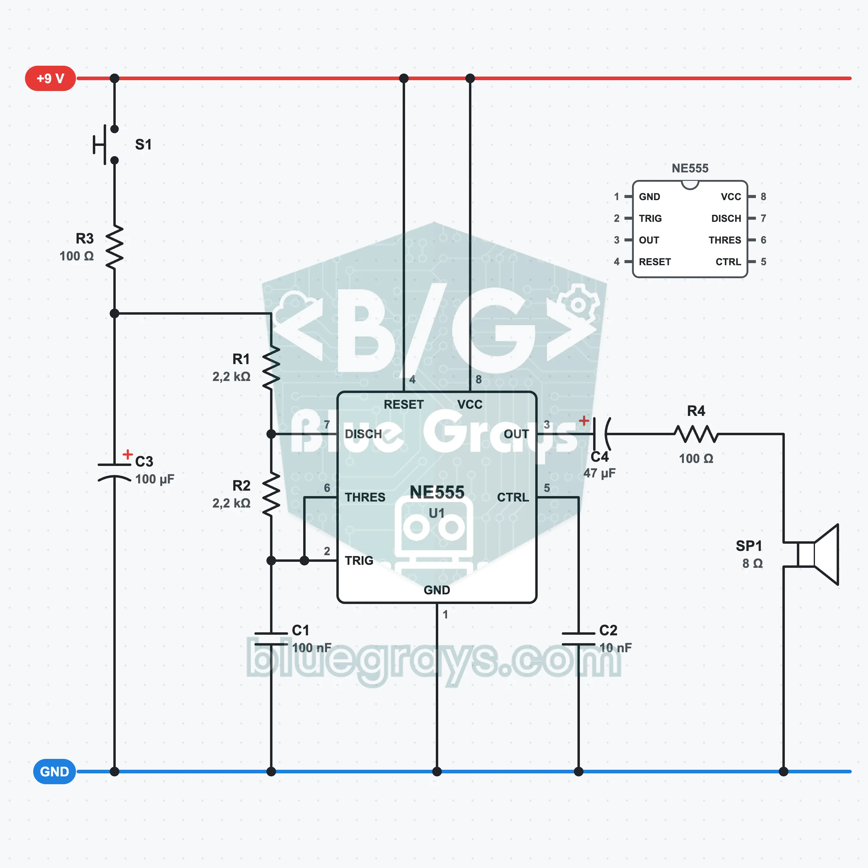
Laser Gun Sound
Press the button and let go: the speaker gives a sliding "pew" sound like in science fiction films. The sound starts at about 2.1 kHz and fades out within a quarter of a second, dropping in pitch as it goes. The tone comes from a single NE555; the slide is made by a 100 µF capacitor that starts discharging the moment you release the button. The speaker is not connected straight to the output, but through a capacitor and a resistor. This circuit is just a sound effect.
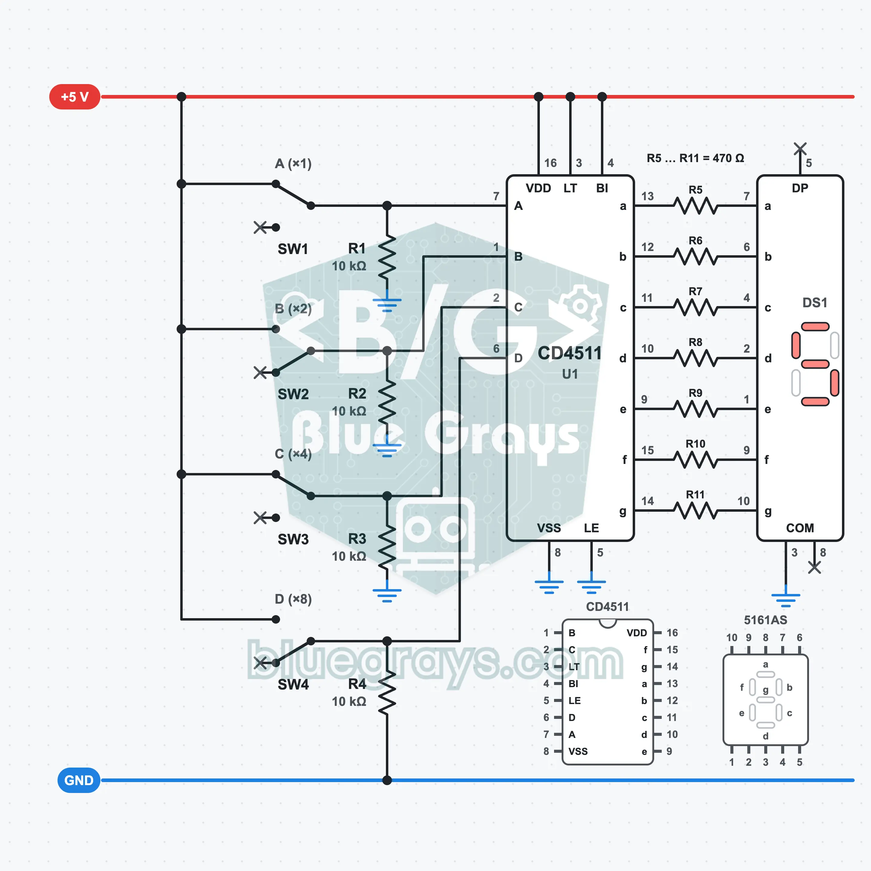
Binary to 7-Segment: CD4511 Decoder
Set a binary number with four slide switches and see it as a digit on the display: 0101 gives 5, 1001 gives 9. The CD4511 does the conversion; it looks at its four inputs and decides which bars light on the common cathode 7-segment display. For numbers from 10 to 15 the display goes blank on purpose. You learn the 8, 4, 2, 1 place values, what a decoder does and why the inputs are held steady with pull-down resistors.
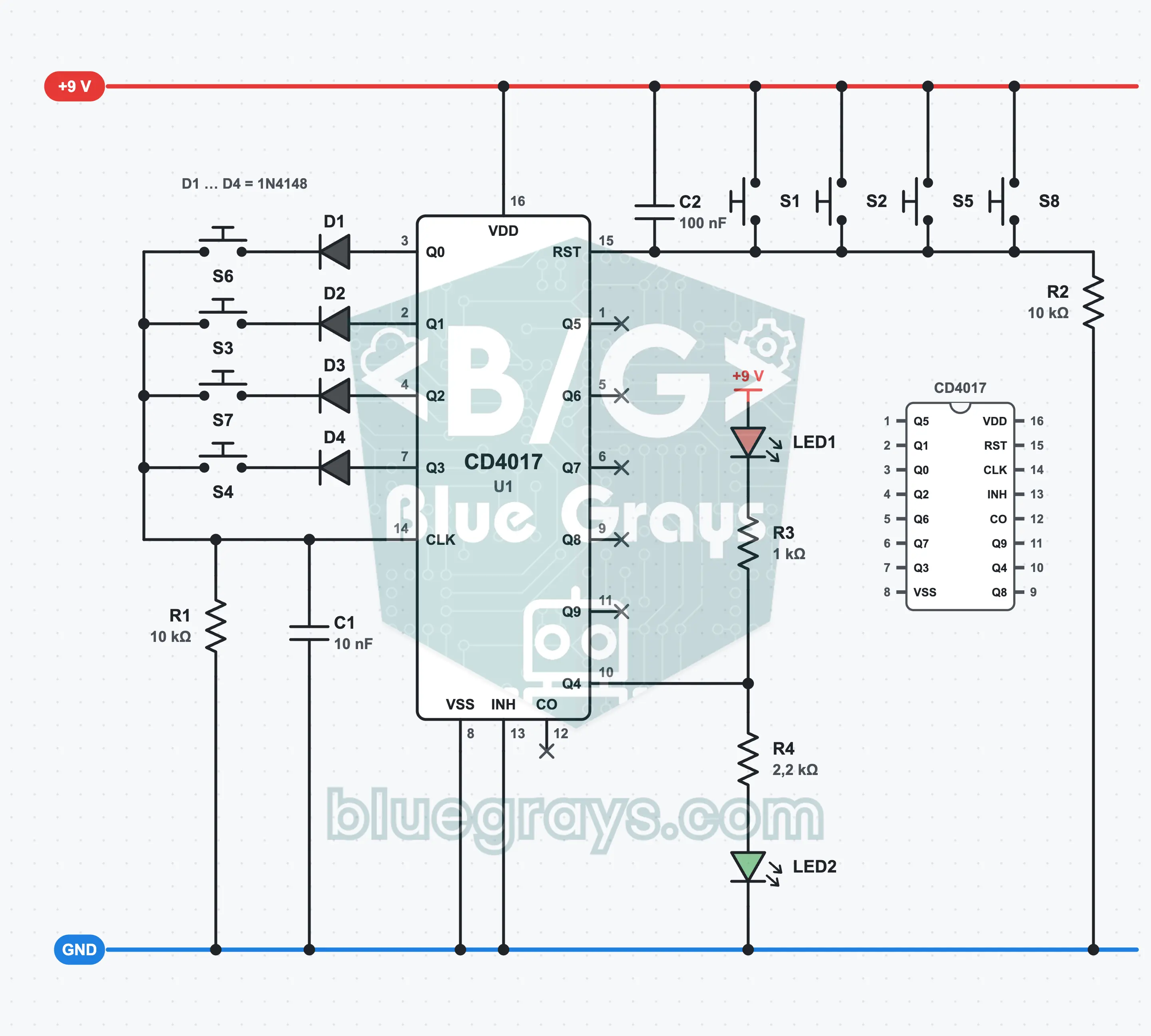
Sequential Code Lock: Push-Button Code with the CD4017
Press four buttons in the right order: the red LED goes out, the green LED lights and the lock stays open. Touch one of the trap buttons in between and everything starts over. The order is kept by the CD4017 counter: only the button connected to whichever output is 1 at that moment can move the counter on by one step. Four diodes keep the buttons apart from each other. This is a game and learning circuit, not a real security lock.
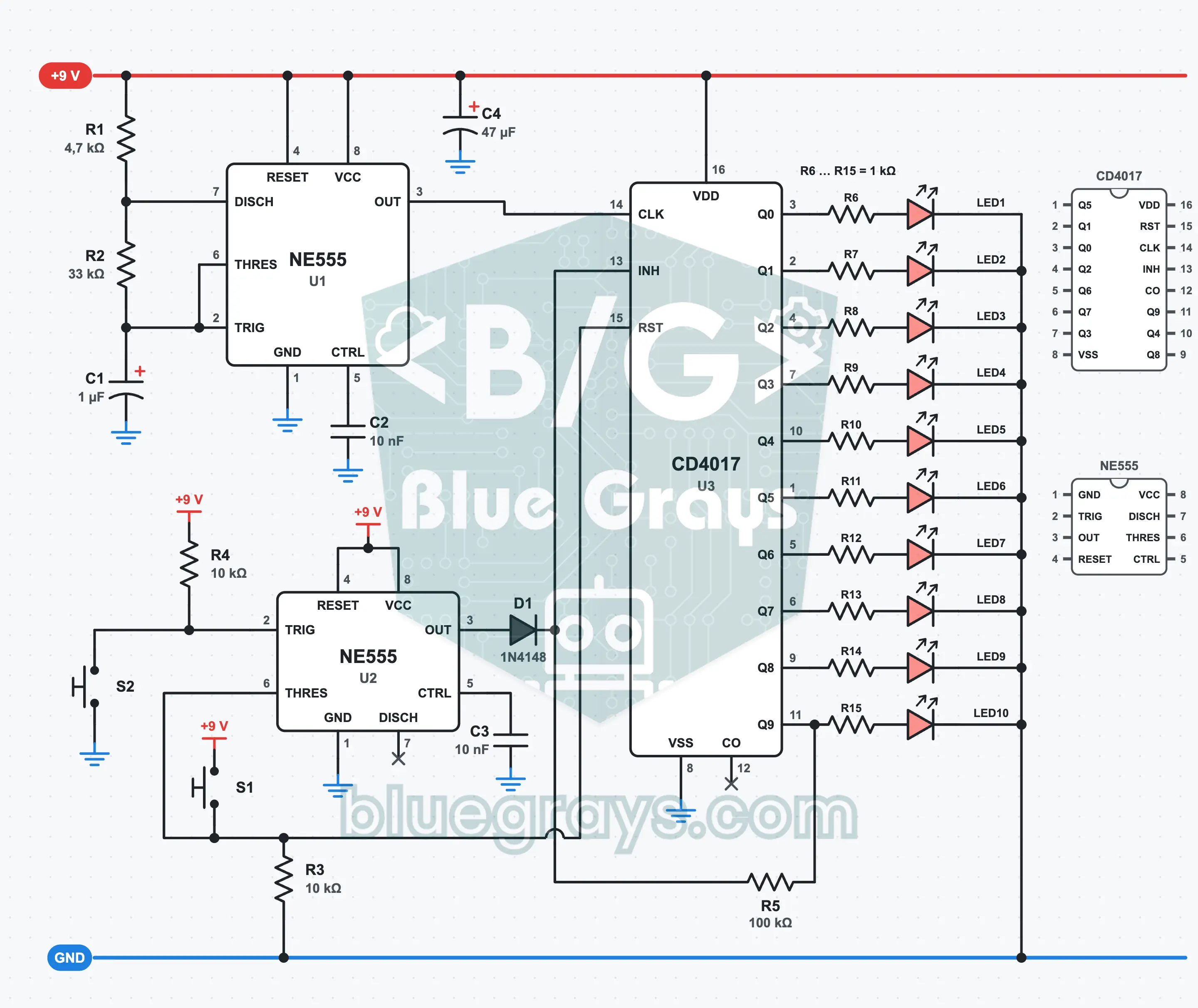
Reaction Time Tester: How Fast Can You Stop the Light?
Your friend holds START down and lets go whenever they like: the light starts running along ten LEDs. You press STOP as soon as you see it move; the LED where the light stops shows your reaction time. The NE555 clock lights each LED for about 49 ms, the CD4017 counts the steps, and a second NE555 remembers START and STOP. If you are too late, the light stops at the last LED.
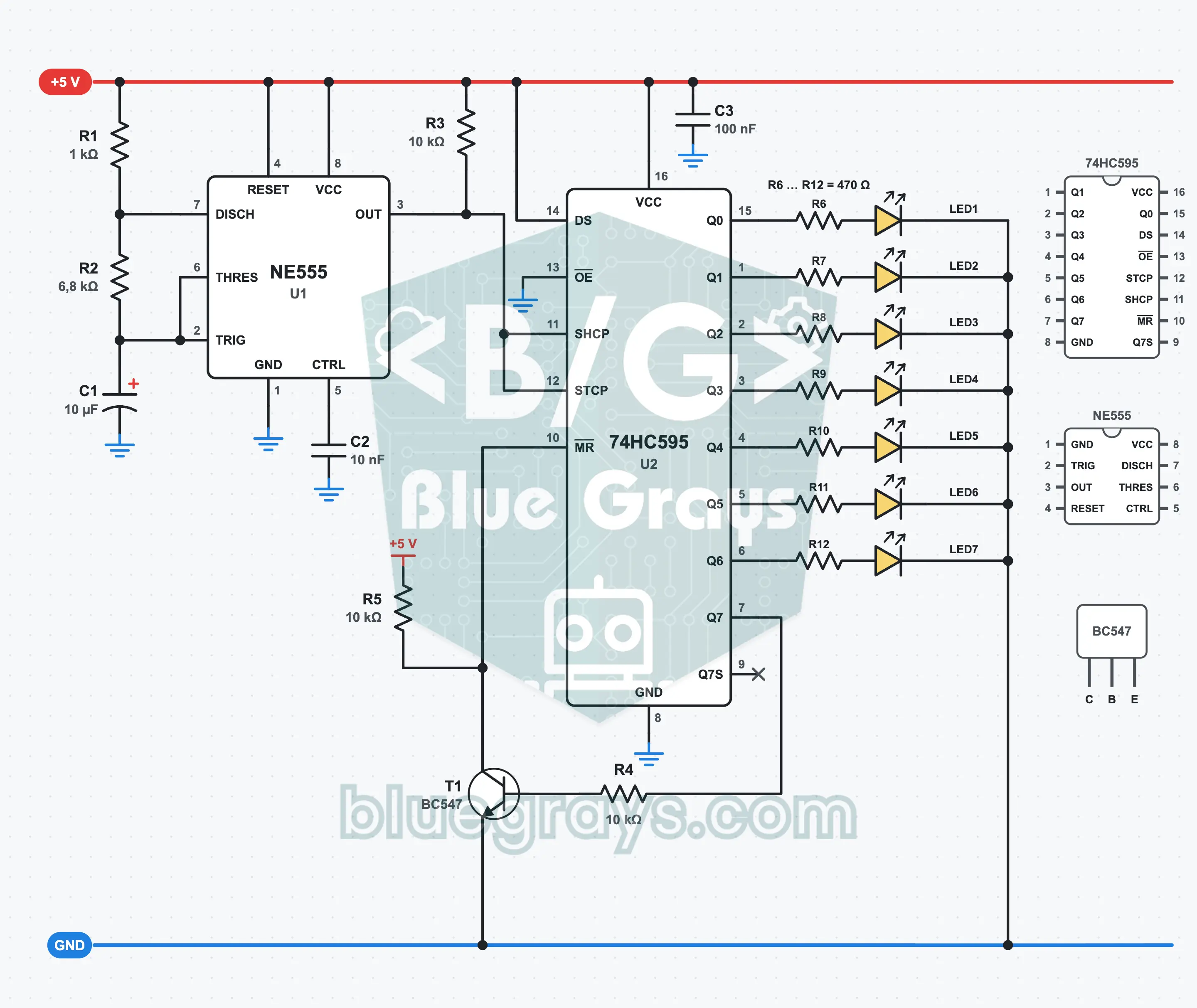
Sequential Turn Signal: A Filling Light Bar
Like the turn signal on new cars: seven yellow LEDs light up one at a time, adding to the bar, the lit ones stay lit, and once the bar is full they all go out and it starts over. An NE555 provides the clock and a 74HC595 shift register keeps the sequence. The eighth output of the shift register drives its own reset pin through a BC547; the bar empties itself. You learn about the shift register, what joining the two clock inputs does and the self-resetting counter.
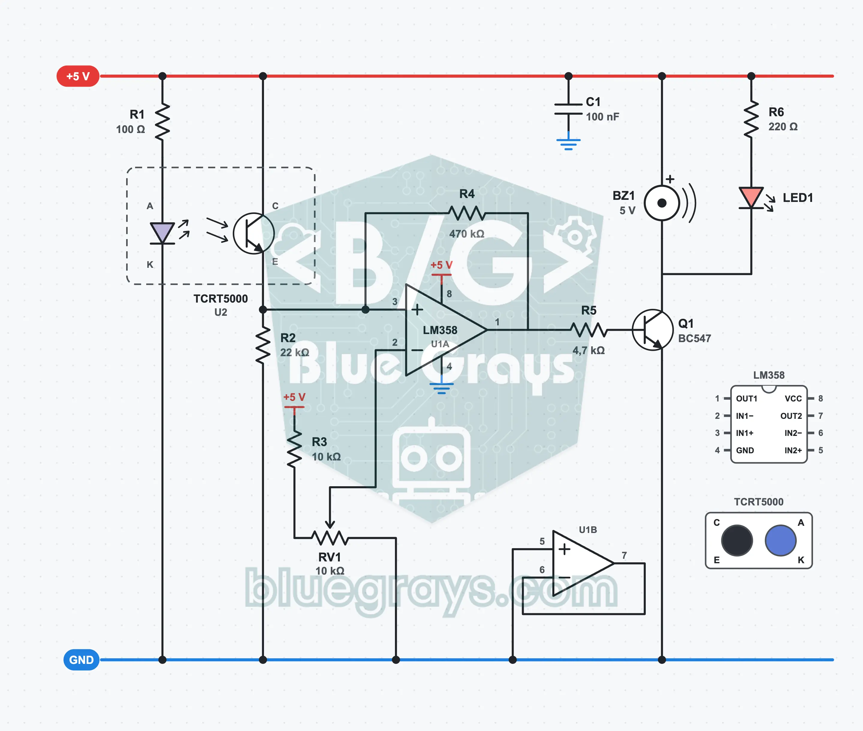
Infrared Obstacle Detector
Bring your hand a few centimeters above the sensor: the red LED lights and the buzzer sounds. The TCRT5000 sends out invisible infrared light and measures what is reflected back; the LM358 compares this with a threshold you set on the potentiometer. A BC547 drives the buzzer and the LED, and a 470 kΩ resistor stops flickering at the threshold. You learn about the comparator, sensing distance by reflected light and hysteresis. The range is only a few centimeters.
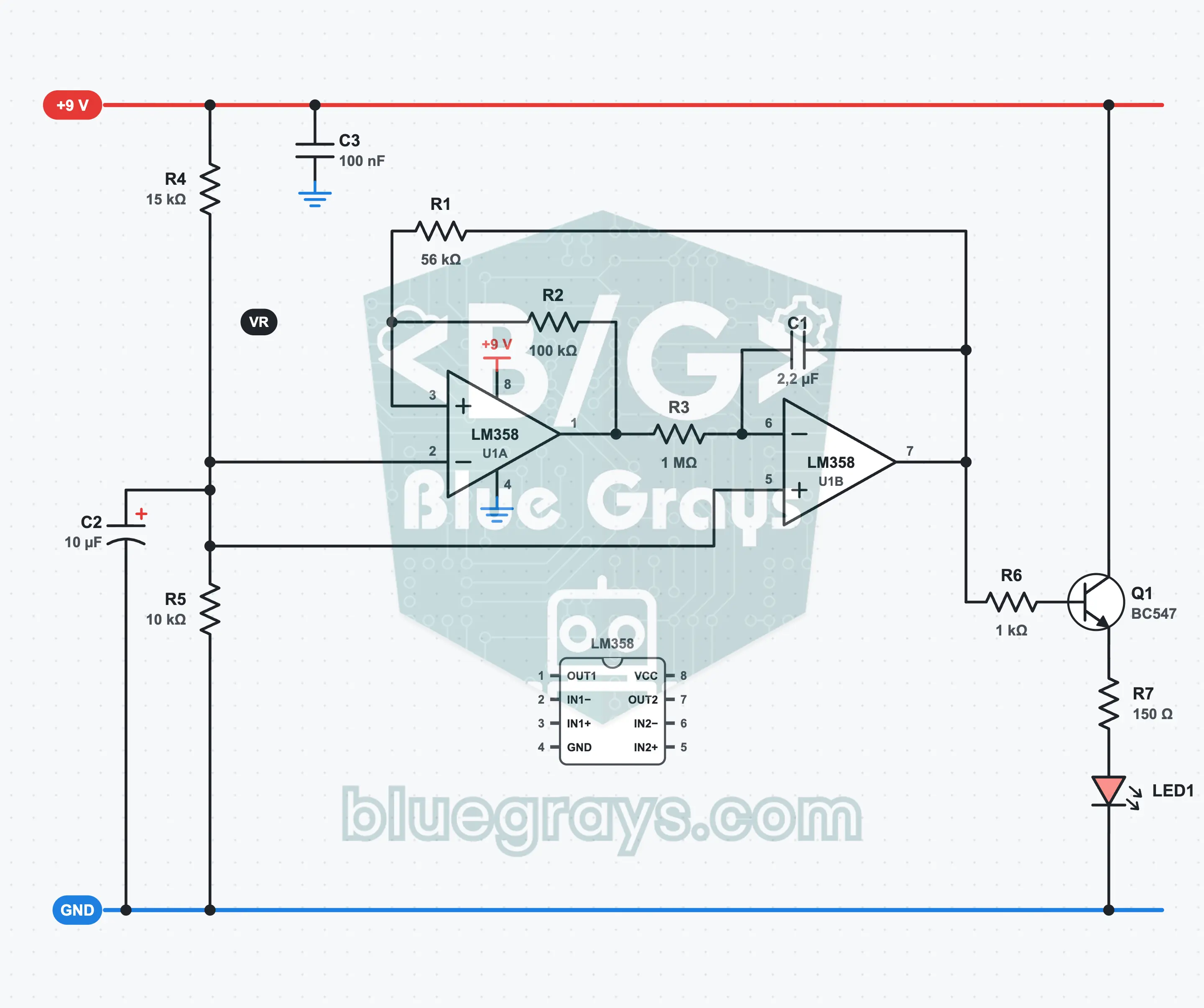
Breathing LED (Triangle Wave)
The red LED slowly brightens over a few seconds, then slowly fades out, like the breathing of someone asleep. The two halves of the LM358 work together: one is a Schmitt trigger, the other an integrator. Together they produce a triangle wave of about 5 seconds. A BC547 follows this wave and drives the LED current from zero up to 18 mA. You learn about the virtual ground, a linear ramp made with a constant current, and the emitter follower.
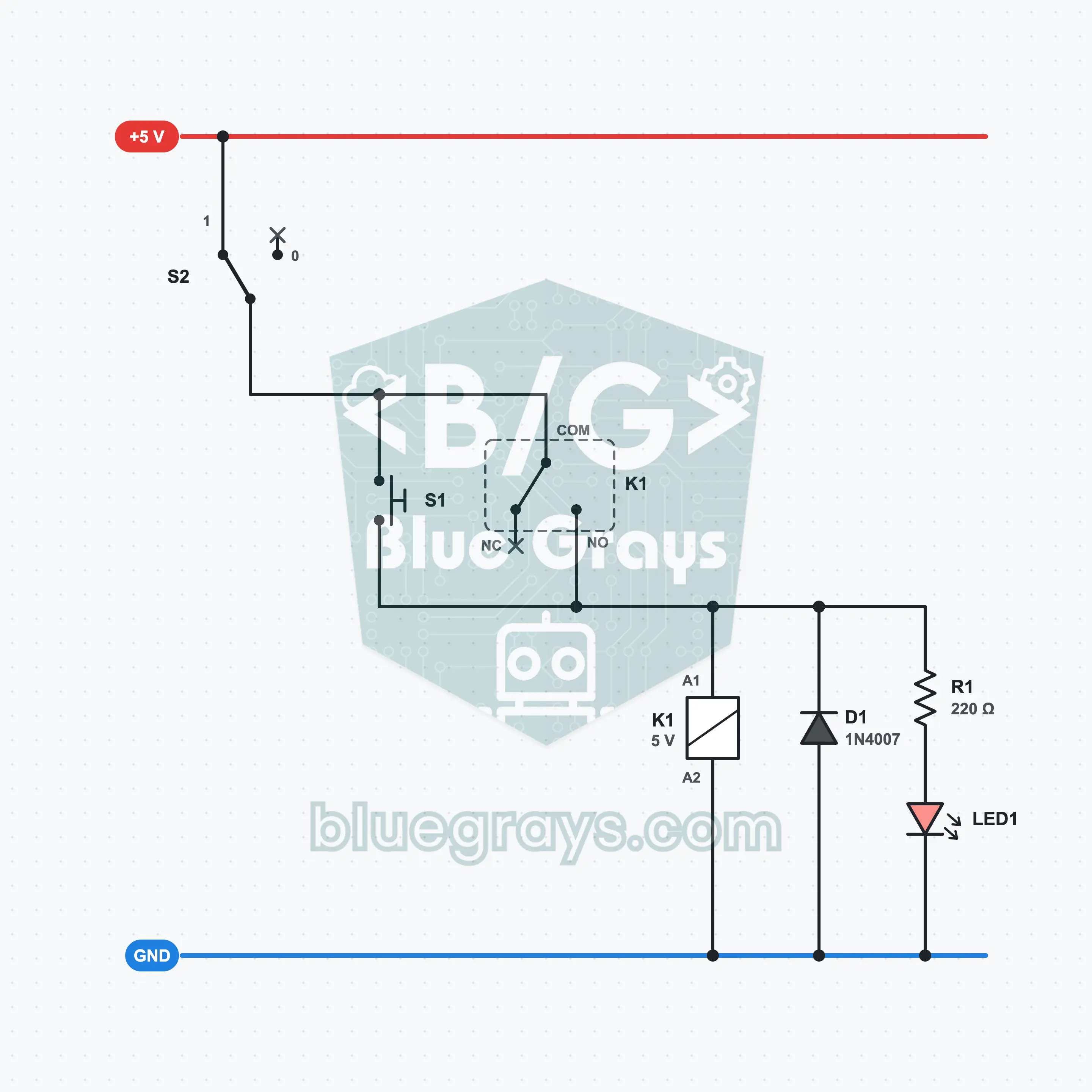
Relay Self-Holding Circuit: Start and Stop
You press the Start button once, the relay pulls in, and it stays pulled in even after you let go of the button; sliding the Stop switch releases it. The secret is the relay's own NO contact: the contact bridges the start button and keeps feeding the coil by itself. This is called self-holding; it is the first circuit in any control wiring course. The 1N4007 diode connected in reverse across the coil protects the switch from the reverse voltage spike.
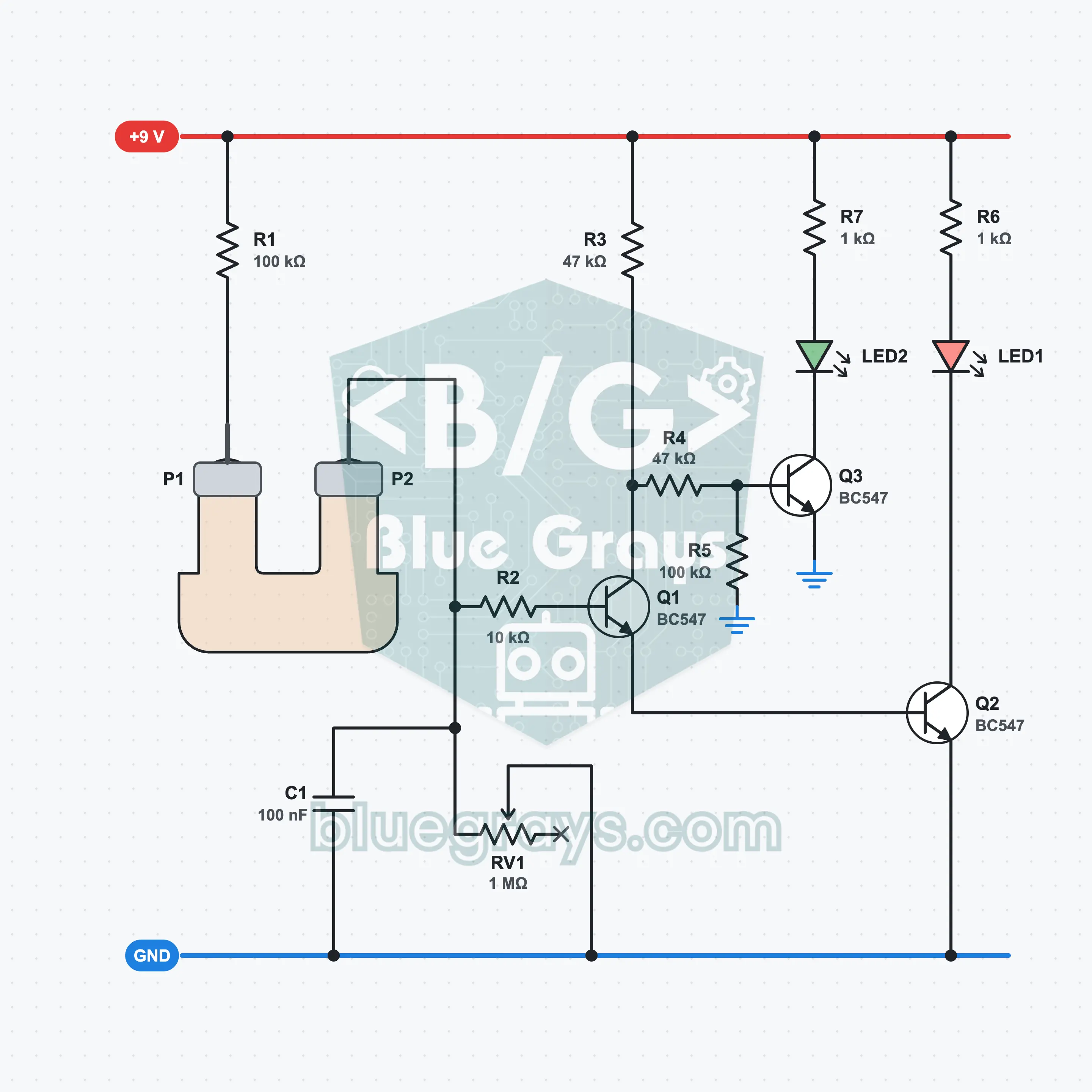
Lie Detector: A Party Game That Measures Skin Resistance
A party game that puts the green LED out and lights the red one when your fingers sweat. Foils on two fingers of one hand measure skin resistance; excitement means sweat, so the resistance drops. Three BC547s amplify this tiny current, and the RV1 pot sets the threshold to your own calm value. It is not a real lie detector: it shows excitement and moisture, not lies. Results vary a lot. You explore skin conductivity, the voltage divider and a Darlington pair.
Yuqori daraja10 ta sxema
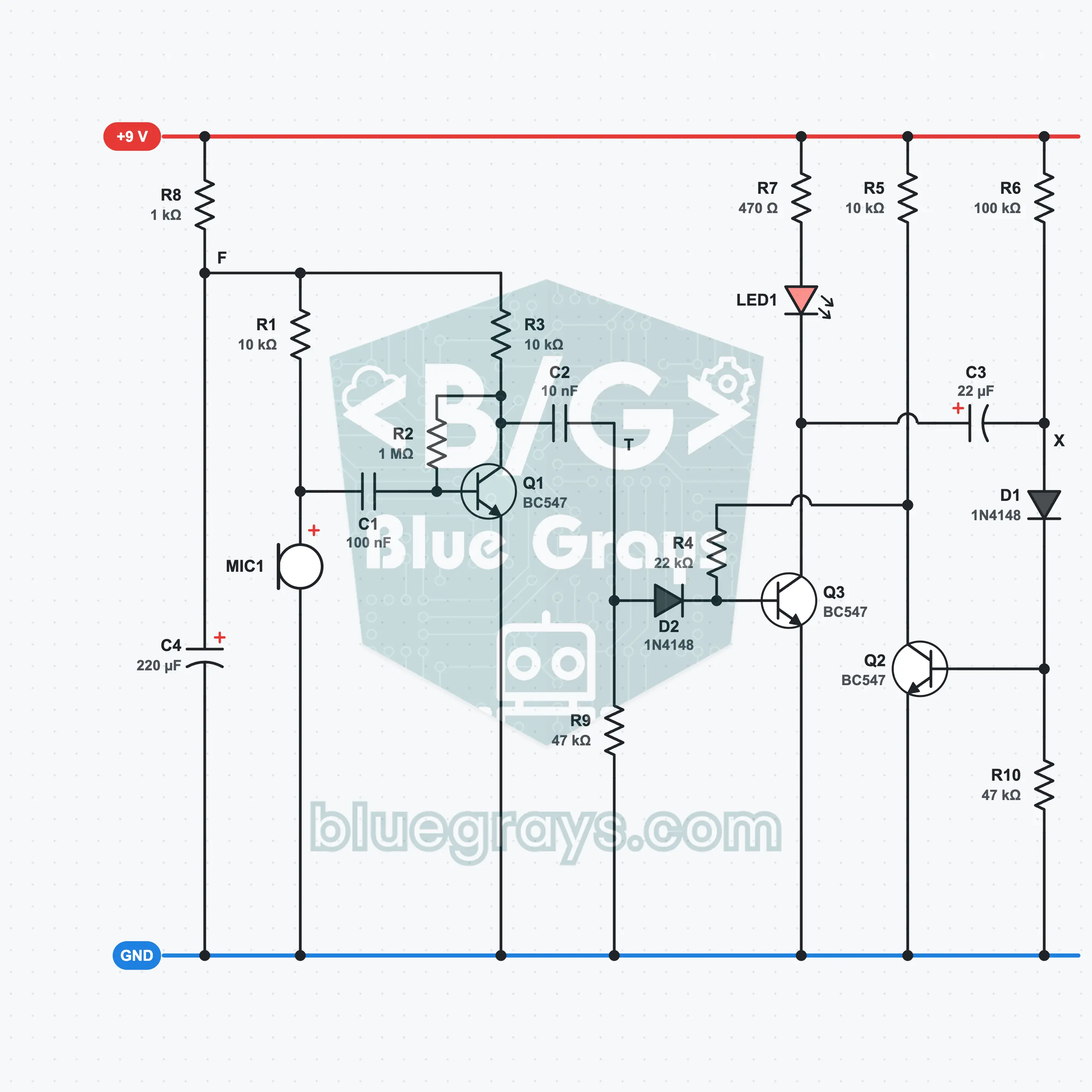
Clap-Activated LED: A Sound Detector with Three BC547s
Clap your hands: the red LED lights, stays on for about 1.6 seconds and goes out by itself. There is no IC: an electret microphone picks up the clap, a BC547 amplifier lifts the few-millivolt signal to the volt level, and a one-shot circuit built with two BC547s keeps the time. You learn amplifying a small signal, coupling with a capacitor, choosing direction with a diode and filtering the supply.
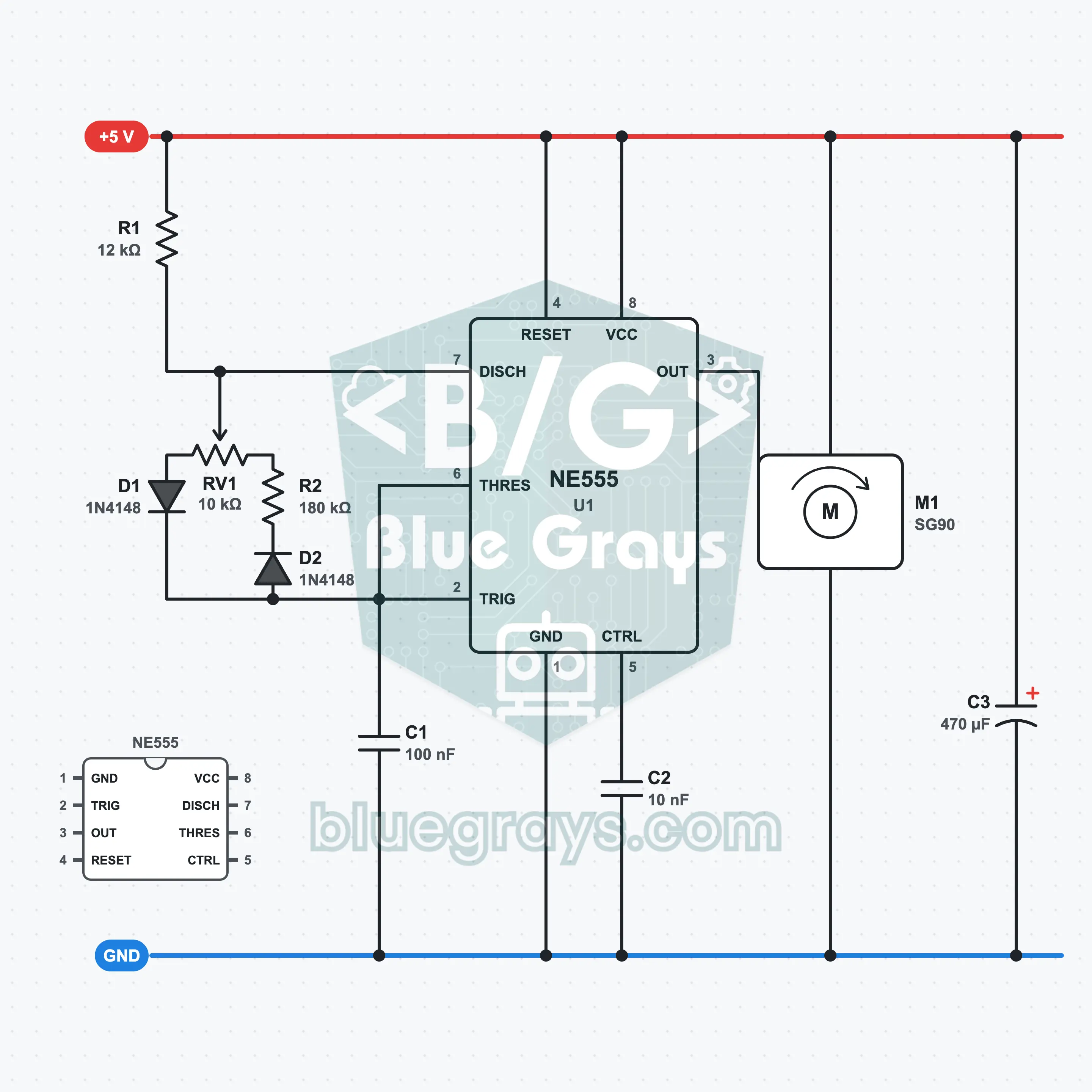
Servo Tester with a 555: Angle Control with a Pot
Turn the pot and the servo arm follows it. The NE555 produces a pulse about every 19 ms, and the pot sets its length: at 1.1 ms the arm goes to one end, at 2 ms to the other. Two 1N4148 diodes separate the charging and discharging paths; because the pot is shared between the two paths, the period does not change while the pulse gets longer. The SG90 needs 4.8 to 6 V, so the circuit is powered with 5 V from the MB102.
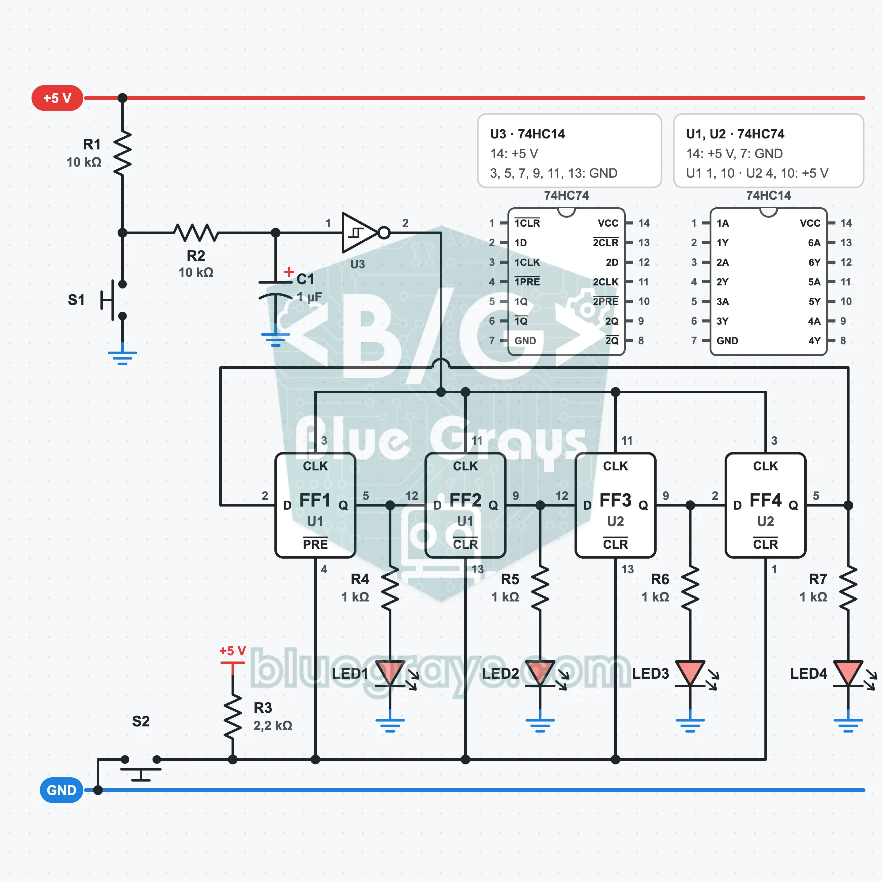
Ring Counter: A Rotating Light on Four LEDs with the 74HC74
Press S2: LED1 lights and the other three go out. Then each press of S1 moves the single light one LED along, and after LED4 it returns to LED1. The four D flip-flops in two 74HC74s (U1, U2) are connected like a ring: the Q output of the last flip-flop comes back to the D input of the first. S2 loads the starting pattern through the set and reset inputs. The clock comes from S1, debounced with a 74HC14 (U3).
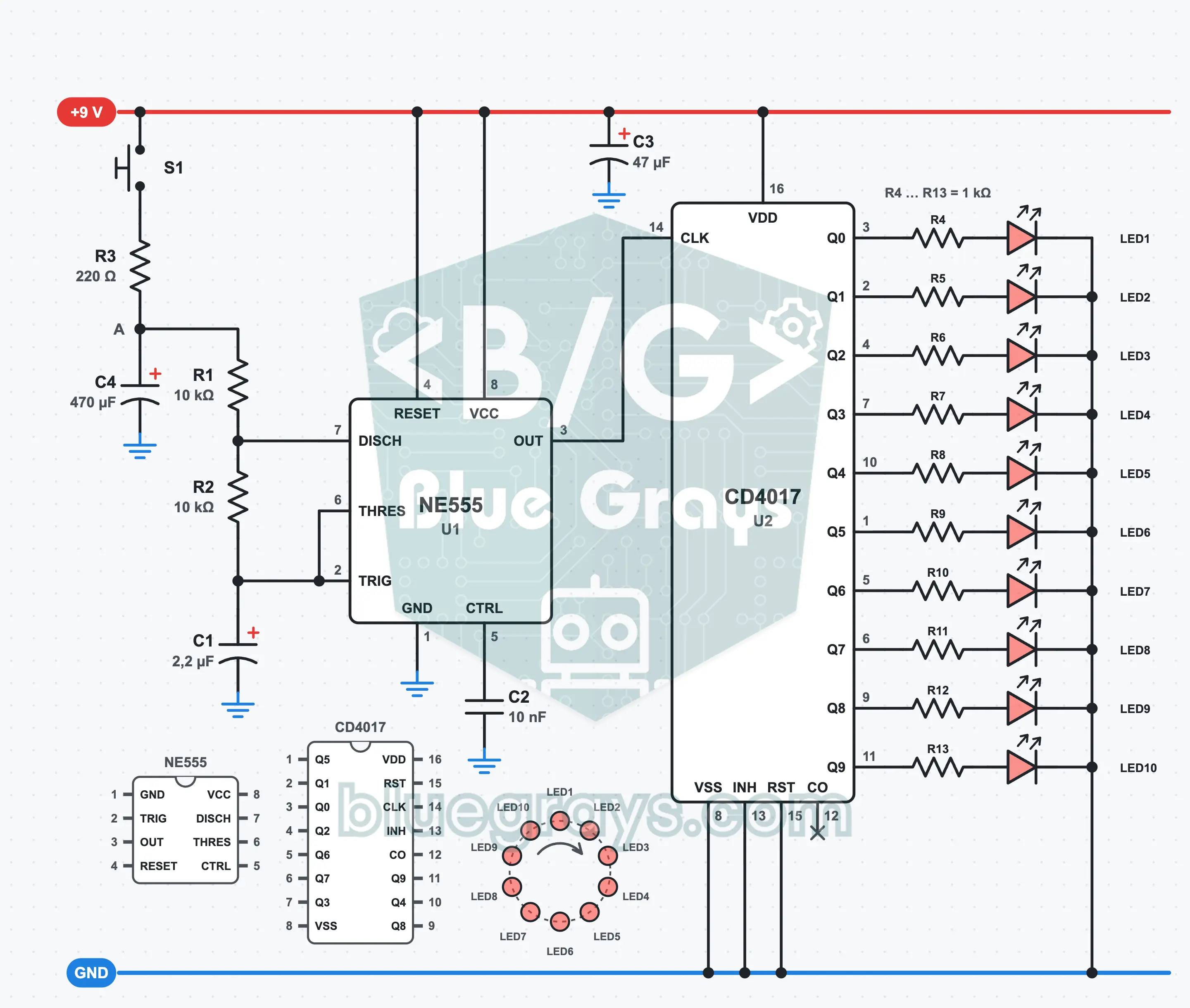
Wheel of Fortune: A Light That Slows Down and Stops with the 555 and 4017
Press the button and a light spins fast around a ten-LED wheel; let go and it slows down and stops on one LED. While the button is held, the NE555 (U1) takes about 21 steps a second; once S1 is released, the clock slows as C4 discharges and stops in about 6 seconds. The CD4017 (U2) lights the ten LEDs in turn. You learn about the 555 threshold voltage, the charge stored in a capacitor and why the result cannot be known in advance.
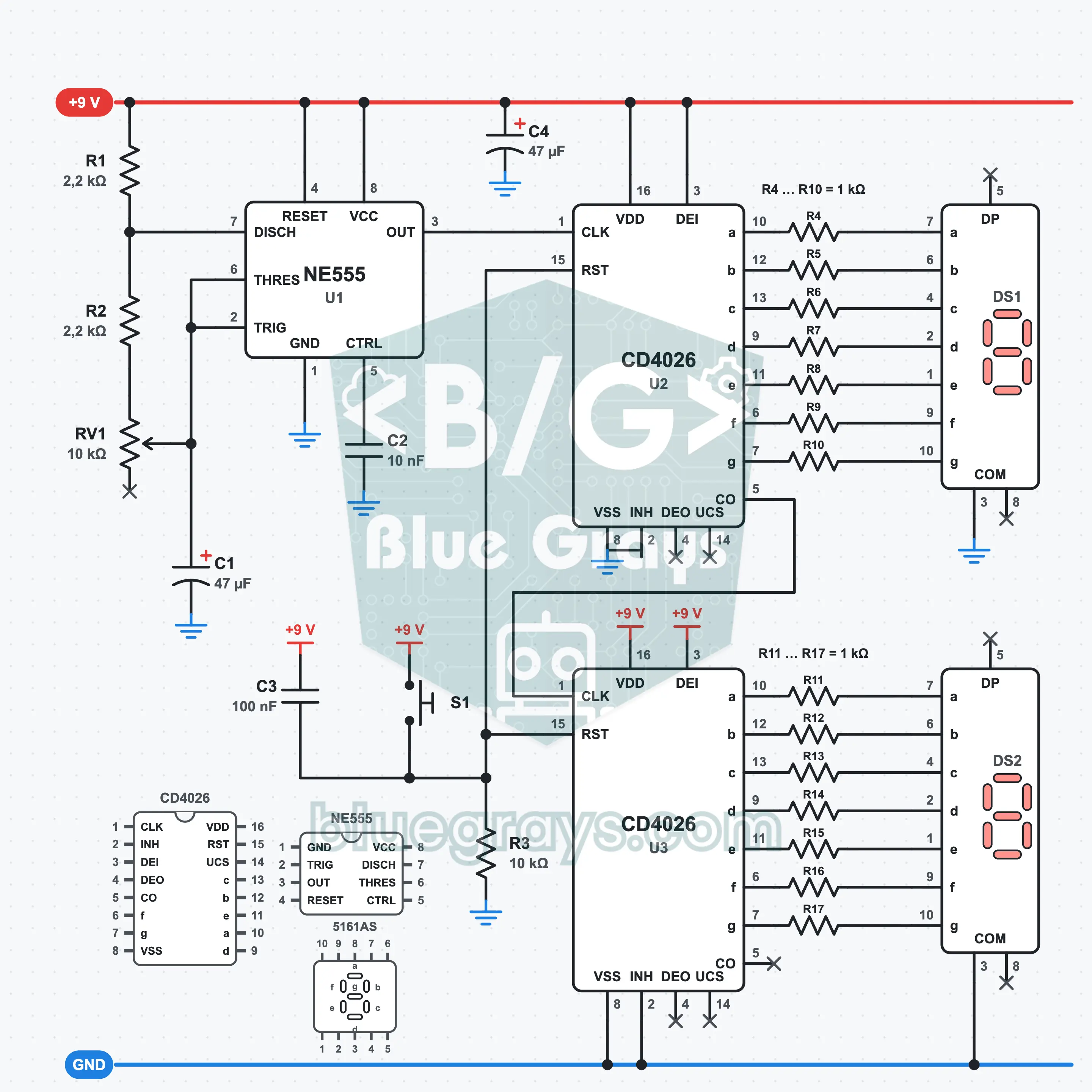
00-99 Counter: A Two-Digit Display with Two CD4026s
The two-digit display counts from 00 to 99, then returns to 00. U1 (NE555) produces pulses at 1.2 to 4.6 per second, set with RV1; the ones counter U2 goes up by one on every pulse. The carry output of U2 (pin 5) rises as it passes from 9 to 0 and advances the tens counter U3 by one step. S1 pulls both digits to 00 at once.
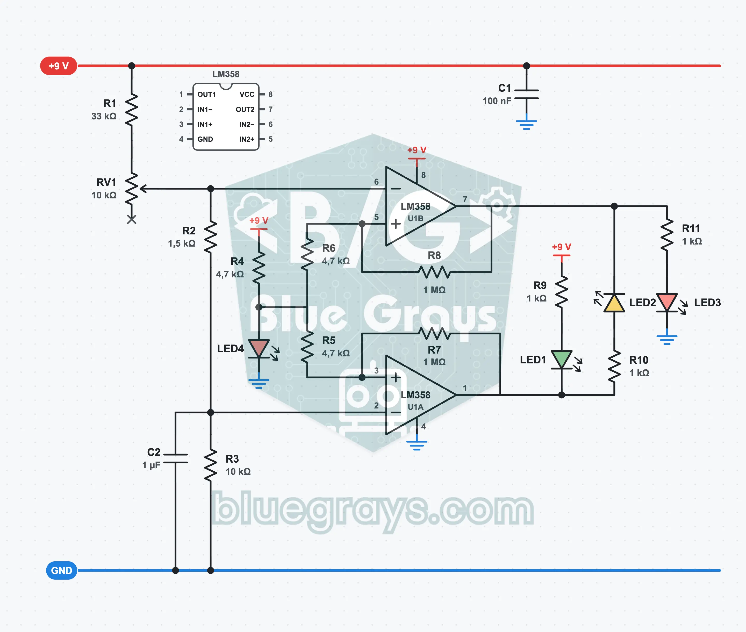
Battery Level Indicator: LM358 and Three LEDs
A battery level indicator that shows how full a 9 V battery is with three LEDs: green above 8.4 V, yellow down to 7.25 V, red below that. The circuit is powered by the battery it measures. That is why the forward voltage of LED4 becomes a reference that does not depend on the battery. The two halves of the LM358 compare this reference with voltages from the resistor ladder, and you calibrate once with RV1.
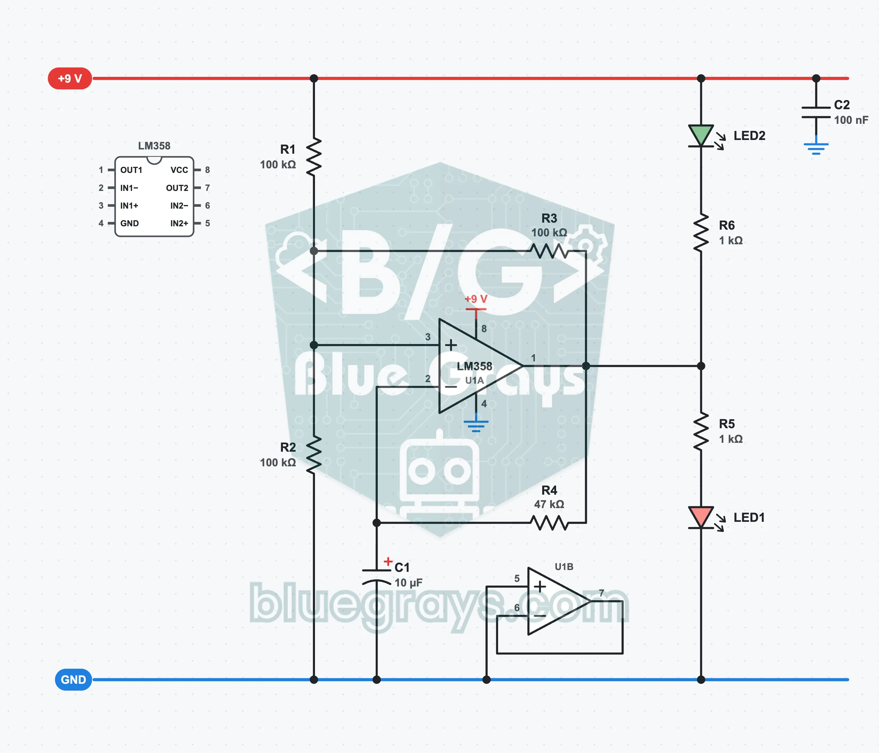
Op-Amp Flasher: Two LEDs Lighting in Turn with the LM358
With a single LM358, a few resistors and one capacitor, you make your own clock signal: the red and green LEDs light in turn about 1.5 times a second. R3, fed back from the output to the + input, sets two separate thresholds, and C1 charges and discharges between them. You learn about the relaxation oscillator, hysteresis and how the output limits of an op-amp on a single supply affect the speed.
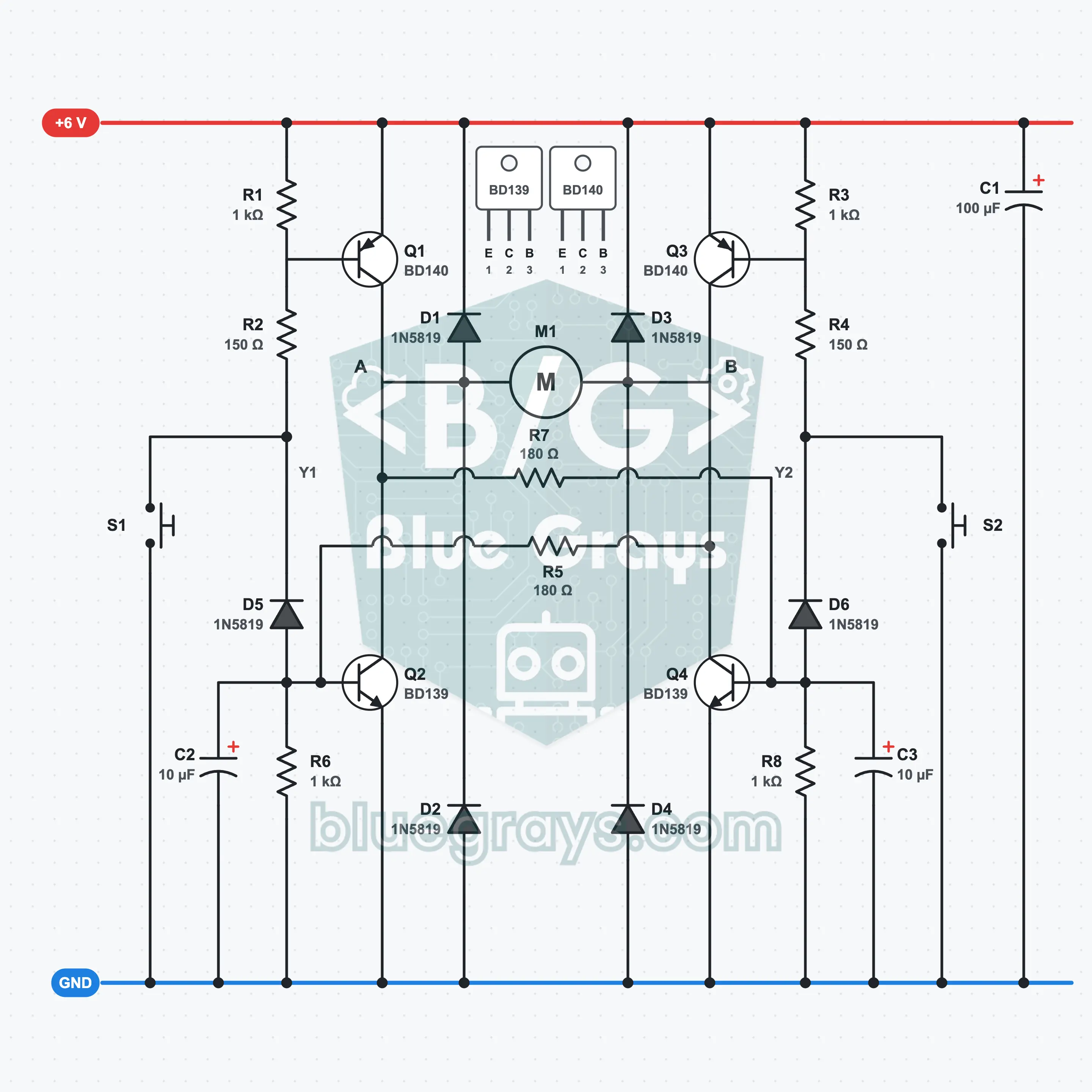
Two-Button Motor Direction: A Four-Transistor Mini H-Bridge
Press S1 and the motor runs forward; press S2 and it runs in reverse. Four transistors connect the two motor terminals to + and GND in turn; this is called an H-bridge. Each button turns on two diagonal transistors: S1 turns on Q1 and Q4, S2 turns on Q3 and Q2. When you press both, D5 and D6 keep the lower transistors off, the motor stops safely, and no short circuit flows through the same branch.
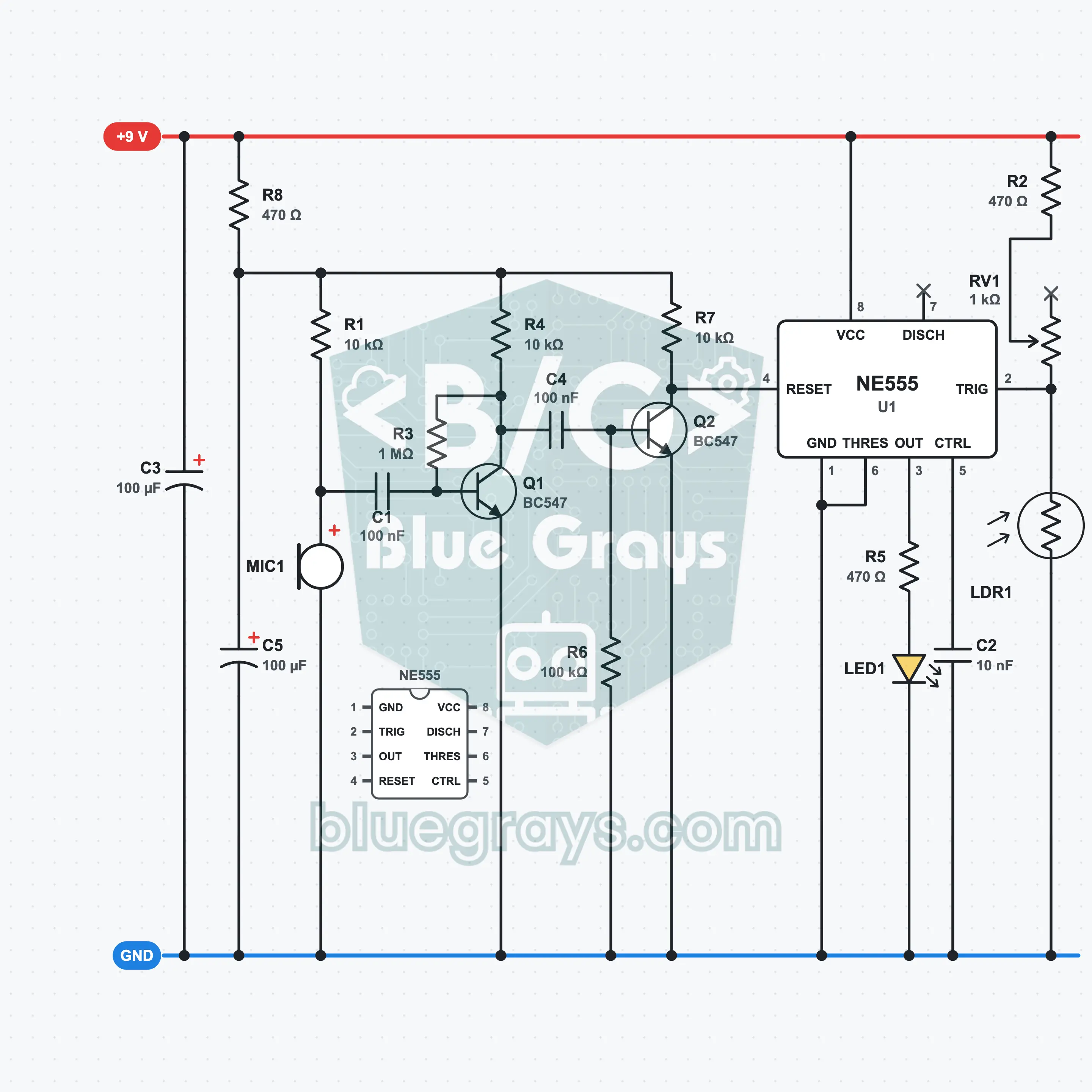
Electronic Candle: An LED You Blow Out
Hold your phone's light over the LDR: the yellow LED lights and stays lit even after you take the light away. Blow on the microphone from close up: it goes out. Whether it is lit or out is remembered by an NE555 working in bistable mode; the blow is picked up by an electret microphone and an amplifier with two BC547s. The microphone cannot tell a blow from a sound: a clap or a loud sound close by can also put the LED out. This is a toy circuit; there is no real flame.
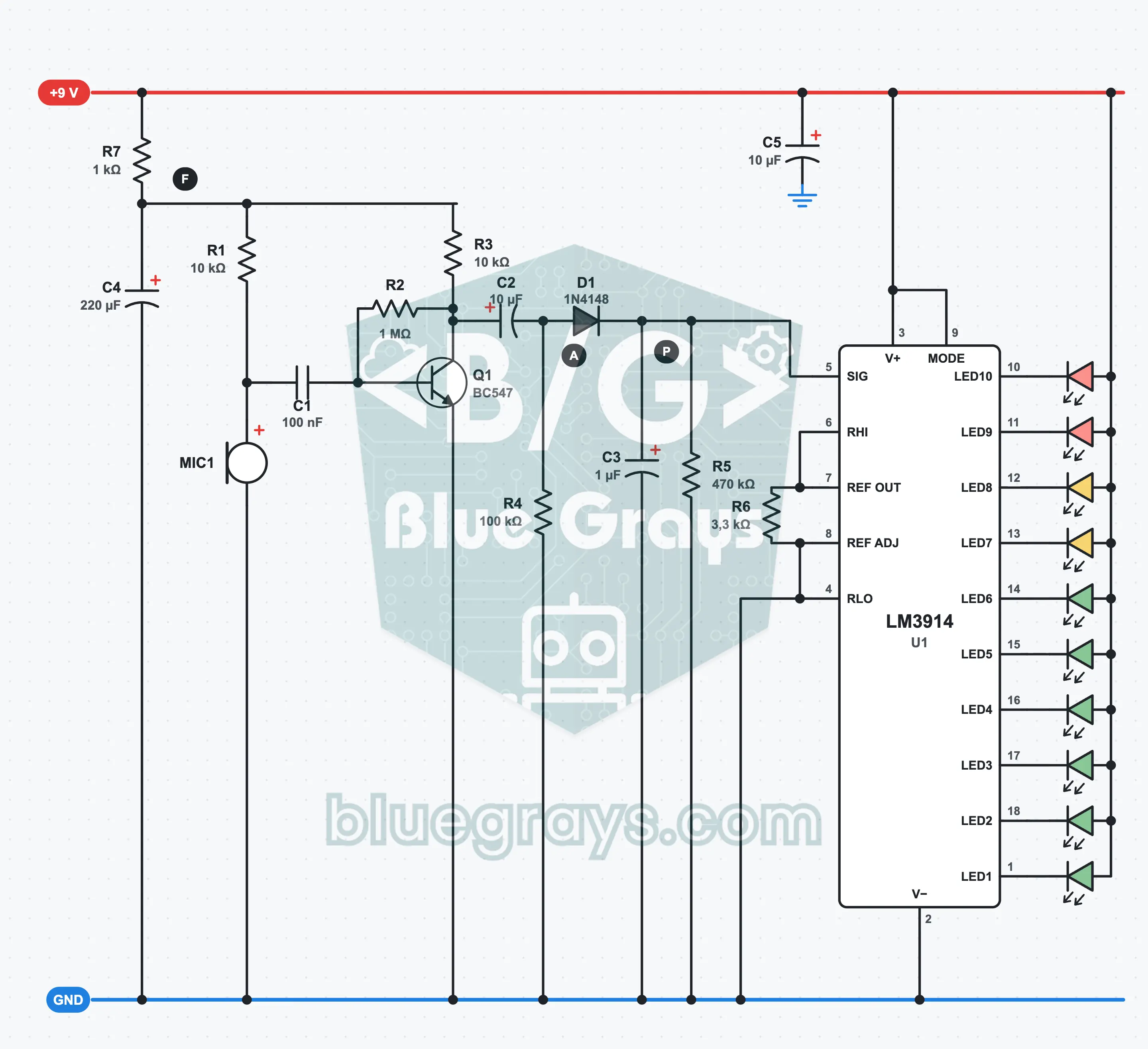
LED VU Meter: A Light Bar That Rises with Sound
Talk into the microphone, clap or bring a speaker close: the ten-LED bar rises with the loudness of the sound and drops back in about a second when it goes quiet. A BC547 amplifies the microphone signal, a diode and a capacitor hold the peak value of the sound, and the LM3914 divides this voltage into 10 steps and lights the LEDs with a current set by a single resistor. You learn about half-wave rectification, the peak detector and the linear-scale bar graph display.
Mavzu bo‘yicha sxemalar
Asosiy sxemalar(10)
Tranzistor sxemalari(22)
- Transistor as a Switch: Lighting an LED with a Small Current
- Touch Switch: A Finger-Activated LED with a Darlington Pair
- LED That Lights in the Dark: LDR and Transistor Night Light
- Broken-Beam Alarm: A Light Barrier with an LDR and Buzzer
- Water Level Alarm: Two-Transistor Water Detector
- Thirsty Plant Indicator: An LED That Lights When the Soil Dries Out
- Temperature Alarm: Two-Transistor Heat Warning with an NTC
- Driving a Relay: Relay Control with a Transistor and Diode
- Transistor Flip-Flop: Two-LED Flasher Circuit
- Transistor Memory: Two-Button Flip-Flop Circuit
- Transistor Timer: Press the Button, Light for 3 Seconds
- Delayed-Off Light: Transistor Staircase Timer
- Logic Gates with Transistors: NOT, NOR and NAND
- Broken Wire Alarm: A Two-Transistor Latching Alarm
- Two-Transistor Beep Circuit: A Tone with the BC547 and BC557
- Clap-Activated LED: A Sound Detector with Three BC547s
- Magnetic Door Alarm: A Latching Alarm with a Reed Switch
- Two-Button Motor Direction: A Four-Transistor Mini H-Bridge
- Water Level Indicator (4 Levels)
- Static Electricity Detector
- Remote Control Tester: See the Invisible Light
- Lie Detector: A Party Game That Measures Skin Resistance
555 taymer sxemalari(20)
- 555 Flasher: Blinking LED Circuit
- Adjustable-Speed Flasher: 555 Circuit with a Potentiometer
- Two LEDs Lighting in Turn: Source and Sink with the 555 Output
- 555 Timer: Press the Button, Light for 5 Seconds
- 555 Flip-Flop: Two-Button Memory Circuit
- One-Button On/Off: Press to Light, Press to Switch Off with the 555
- Touch Timer: A Finger-Triggered 555
- Buzzer Tone Generator: Audio Frequency with the 555
- Mini Piano: An Eight-Key Octave with the 555
- Metronome: Adjustable Tempo and Click Sound with the 555
- Police Siren: A Rising and Falling Sound with Two 555s
- Two-Tone Doorbell: A Ding Dong Sound with the 555
- PWM LED Dimming: Brightness Control with a 555 and a Pot
- PWM Motor Speed: DC Motor Control with a 555 and a MOSFET
- Darkness Alarm: A 555 Circuit That Sounds When the Light Goes Out
- Servo Tester with a 555: Angle Control with a Pot
- Steady Hand Game
- Earthquake Alarm: A Circuit That Sounds When Shaken
- Laser Gun Sound
- Electronic Candle: An LED You Blow Out
Mantiqiy element sxemalari(13)
- Basic Gates: AND, OR and NOT Circuit
- NAND and NOR: Inverting Gates
- Every Gate from NAND: One IC, Three Operations
- XOR: The Gate That Spots the Difference
- See De Morgan for Yourself: Two Circuits, the Same Table
- Half Adder
- Full Adder
- Majority Circuit: Three-Person Voting
- Combination Lock: A Code Circuit with Four Switches
- 2-to-1 Multiplexer: Select One of Two Inputs
- 2-to-4 Decoder: Two Addresses, Four Outputs
- Gate Flasher: A Schmitt Oscillator with the 74HC14
- Binary to 7-Segment: CD4511 Decoder
Trigger sxemalari(10)
- SR Latch: 1-Bit Memory with Two NOR Gates
- Switch Bounce Cleaner: A Debouncer with the 74HC00
- Gated D Latch: 1-Bit Memory with Four NAND Gates
- D Flip-Flop: 1-Bit Memory with the 74HC74
- JK Flip-Flop: Four-Mode Memory with the CD4027
- T Flip-Flop: Divide-by-Two Circuit with the 74HC74
- Toggle with a D Flip-Flop: A Debounced Single-Button Switch
- Who Pressed First? A Quiz Buzzer Circuit: Lockout with the 74HC74
- 4-Bit Shift Register: Shift Bits with the 74HC74
- Ring Counter: A Rotating Light on Four LEDs with the 74HC74
Sanagich sxemalari(15)
- 2-Bit Counter: Count from 0 to 3 with the 74HC74
- 4-Bit Binary Counter: A Circuit That Counts from 0 to 15 with the CD4520
- 4017 Running Light: 10 LEDs Stepped by a Button
- 555 and 4017 Running Light: 10 LEDs with Adjustable Speed
- Back-and-Forth LED Scanner: A Sweeping Light with the 555 and 4017
- Traffic Light: Red, Yellow, Green with the 555 and 4017
- Police Light Bar: Red and Blue Double Flash with the 555 and 4017
- Electronic Dice: Six-LED Dice with the 555 and 4017
- Wheel of Fortune: A Light That Slows Down and Stops with the 555 and 4017
- 0 to 9 Counter: 7-Segment Display with the 555 and CD4026
- Push-Button Scoreboard: A Number That Goes Up with Each Press with the CD4026
- 00-99 Counter: A Two-Digit Display with Two CD4026s
- Sequential Code Lock: Push-Button Code with the CD4017
- Reaction Time Tester: How Fast Can You Stop the Light?
- Sequential Turn Signal: A Filling Light Bar
Operatsion kuchaytirgich sxemalari(8)
Quvvat va ta’minot sxemalari(3)
Komponentlar va asboblar
Sxemalarda eng ko‘p ishlatiladigan komponentlar, sxema yig‘ishda asqotadigan hisoblash asboblari va qo‘llanma maqolalar.


Ko‘p so‘raladigan savollar
Arduinosiz elektron sxema yig‘ish mumkinmi?
Ha. Tranzistor, 555 taymer va mantiqiy mikrosxemalar o‘zi ishlaydi; mikrokontroller ham, kod ham kerak emas. Bu sahifadagi sxemalarning hammasi platasiz va kodsiz: komponentlarni breadboard ga joylashtirasan, batareyani ulaysan va natijani darhol ko‘rasan.
Asosiy elektron sxemalar uchun qanday komponentlar kerak?
Breadboard, 9 V batareya va klemma, jumper simlar, turli qiymatli rezistorlar, LED lar, tugma, bir nechta kondensator va BC547 tranzistor bilan dastlabki sxemalarning ko‘pini yig‘asan. Keyingi sxemalarda NE555, 74HC seriyali mantiqiy mikrosxemalar va CD4017 sanagich qo‘shiladi.
Elektronikani qaysi sxemadan boshlashim kerak?
LED va rezistor sxemasidan boshla: tok, kuchlanish va qarshilik o‘rtasidagi bog‘liqlikni bitta LED bilan ko‘rasan. Keyin tugma bilan LED yoqish, ketma-ket va parallel LED lar va kuchlanish bo‘lgich keladi. Bu to‘rt sxema tranzistor va 555 sxemalarining asosi.
555 taymer bilan qanday sxemalar yig‘iladi?
NE555 uch rejimda ishlaydi. Astable rejimda o‘zi impuls hosil qiladi: miltillagich, ton generatori yoki sanagichning soat signali bo‘ladi. Monostable rejimda tugma bosilgandan keyin ma’lum vaqt yoniq turadigan taymerga aylanadi. Bistable rejimda ikki tugmali oddiy xotira kabi harakat qiladi.
Trigger (flip-flop) sxemasi nima va nimaga kerak?
Trigger 1 bitlik ma’lumotni saqlaydigan sxema; yangi signal kelguncha chiqishi o‘zgarmaydi. U sanagichlar, registrlar va kompyuter xotirasining qurilish bloki. Bu sahifada NOR elementlaridan SR tutqich, keyin D, T va JK triggerlarni yig‘asan.
Mantiqiy elementlarni breadboard da qanday sinab ko‘riladi?
74HC08 (AND), 74HC32 (OR), 74HC04 (NOT) yoki 74HC86 (XOR) kabi mikrosxemani breadboard ga joylashtir, kirishlarga tugma, chiqishga rezistor orqali LED ula. Tugmalarni bosganingda haqiqat jadvalining har bir qatorini LED da ko‘rasan. Ishlatilmayotgan kirishlarni bo‘sh qoldirma; GND ga yoki ta’minot shinasiga ula.