
Knight Rider LED Effect with Adjustable Speed

Video
Elektr sxemasi

Manba kodi
1// ─────────────────────────────────────────
2//   BlueGrays · bluegrays.com
3//   Knight Rider LED Effect with Adjustable Speed
4// ─────────────────────────────────────────
5// A potentiometer sets the speed of the Knight Rider (back and forth) LED
6// effect. A0 is read at every step and its 0-1023 value becomes the delay
7// time (ms).
8//
9// Pins:
10//   D2, D3, D4, D5, D6, D7 -> 6 LEDs (in order)
11//   Each LED with a 330 ohm resistor
12//   A0 -> Potentiometer wiper
13//   (outer legs to 5V and GND)
14
15int ledPins[] = {2, 3, 4, 5, 6, 7};   // LED pins in lighting order
16int potValue;                         // Pot value = delay (ms)
17
18void setup() {
19  // Set all LED pins as outputs
20  for(int i = 0; i < 6; i++) {
21    pinMode(ledPins[i], OUTPUT);
22  }
23}
24
25void loop() {
26  // Forward: D2 to D7
27  for(int i = 0; i < 6; i++) {
28    potValue = analogRead(A0);        // Read the speed (0-1023)
29    digitalWrite(ledPins[i], HIGH);
30    delay(potValue);                  // Wait as many ms as the pot value
31    digitalWrite(ledPins[i], LOW);
32  }
33
34  // Backward: D6 to D3. The end LEDs are skipped so the bounce looks seamless
35  for(int i = 4; i > 0; i--) {
36    potValue = analogRead(A0);
37    digitalWrite(ledPins[i], HIGH);
38    delay(potValue);
39    digitalWrite(ledPins[i], LOW);
40  }
41}
42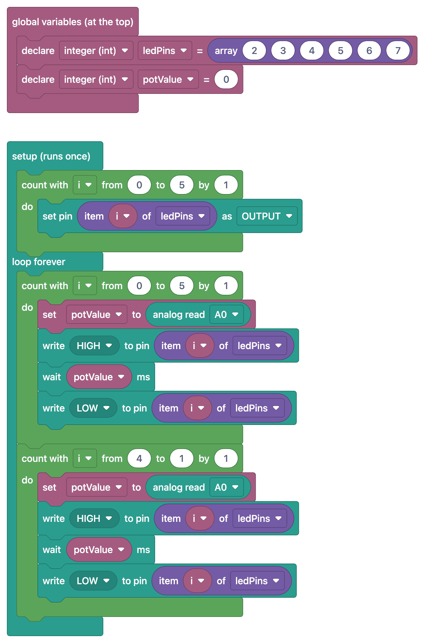
Ko‘p so‘raladigan savollar
What does this project teach that is different from previous ones?
It combines the analog input (potentiometer) with a bidirectional loop: as the light moves back and forth, the potentiometer is read at each step and updated at the moment of delay. This is the basis for changing behavior based on the sensor value.
The reading is fluctuating—how do I stabilize it?
Minor fluctuations in analog readings are normal. Averaging several readings or using the `map()` function to divide the value into coarser intervals (e.g., 10-millisecond intervals) masks the fluctuations.
Can I use a different sensor instead of a potentiometer?
Yes, you can use an LDR, but an LDR does not produce a voltage output on its own. Build a voltage divider with the LDR and a fixed resistor between 5 V and GND, and connect their junction to A0. Then you can use `map()` in the code to convert the measured range to your desired delay range.
Which analog pin should I use?
On the Uno, all pins from A0 to A5 can be used for analog readings. Make sure the pin you use in your code matches the connection in your circuit; since A4 and A5 are also used for I2C, choose A0 if you plan to add a display later.