
Raspberry Pi Pico: Controlling an External LED (Breadboard)
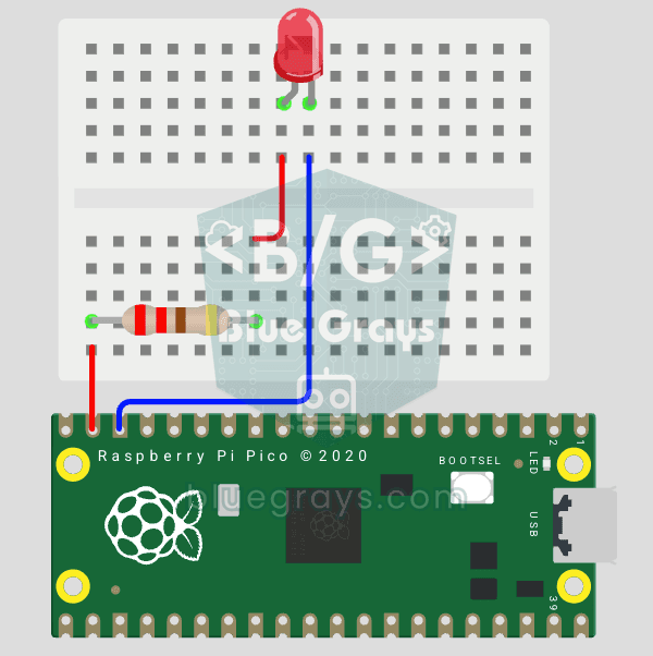
The next step after the Pico's built-in LED: connect an external LED on a breadboard and control it through pin GP14. You'll learn how to use any of the Pico's GPIO pins as an output, the LED's polarity (long leg = anode/+, short leg = cathode/–) and why a current-limiting resistor (220Ω) is a must. Without the resistor, too much current flows through the LED and it can burn out.
Video
Elektr sxemasi
Manba kodi
1# ─────────────────────────────────────────
2#   BlueGrays · bluegrays.com
3#   Raspberry Pi Pico: Controlling an External LED (GP14 + Breadboard)
4# ─────────────────────────────────────────
5# An external LED on a breadboard blinks every 0.5 s. Shows how to use any
6# Pico GPIO pin as an output.
7#
8# Pins:
9#   GP14 -> 220 ohm resistor -> LED (+, long leg)
10#   Red LED (-, short leg) -> GND
11
12from machine import Pin
13import time
14
15# ============ PIN / PIN ============
16LED_PIN = 14                    # Any free GPIO
17led = Pin(LED_PIN, Pin.OUT)
18
19print("== BlueGrays: Pico External LED Blink ==")
20print("LED pin: GP" + str(LED_PIN))
21print("500ms on 500ms off")
22
23# ============ MAIN LOOP ============
24while True:
25    led.on()                    # Turn the LED on
26    print("[LED] ON")
27    time.sleep(0.5)
28
29    led.off()                   # Turn the LED off
30    print("[LED] OFF")
31    time.sleep(0.5)
32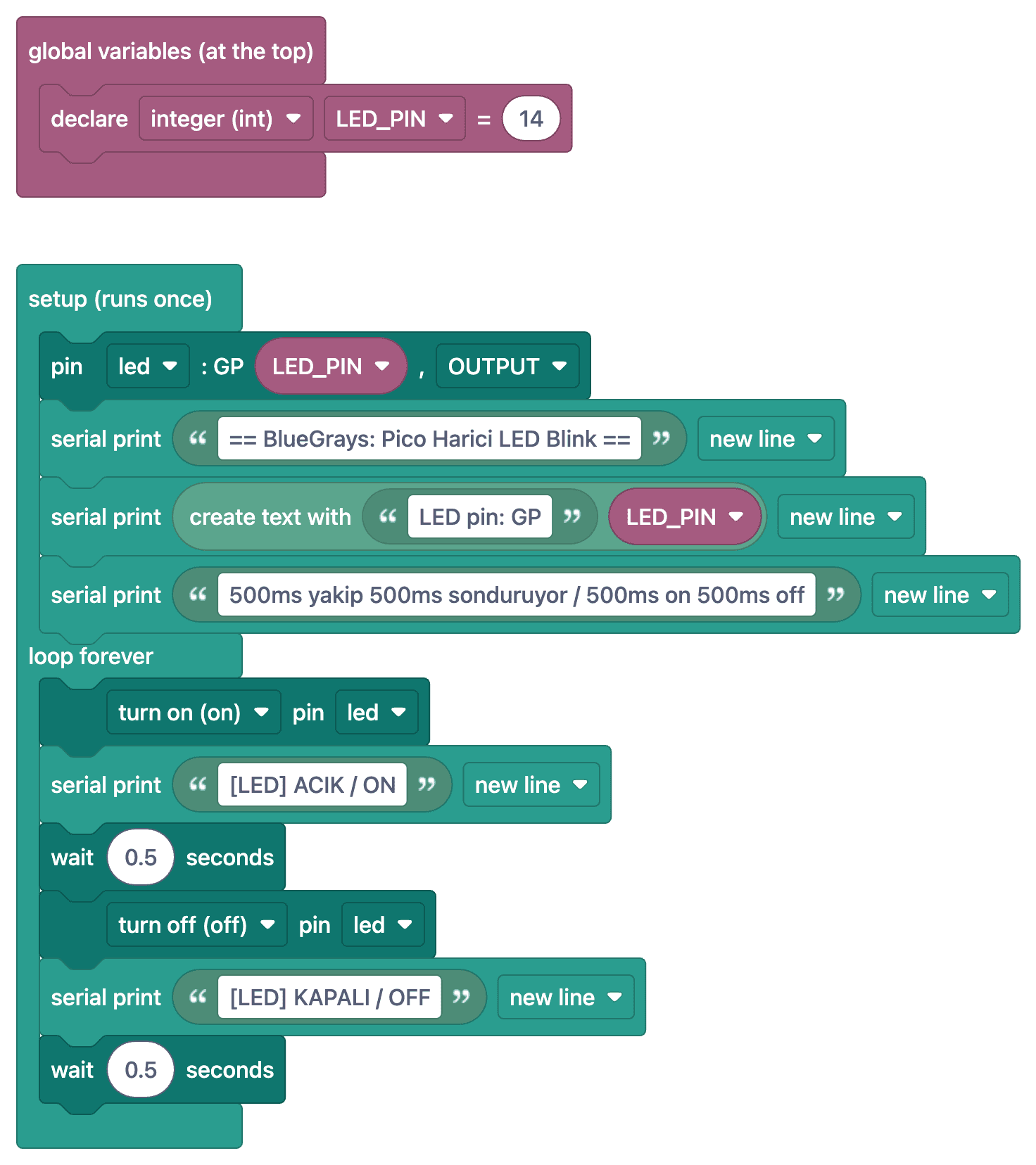
Ko‘p so‘raladigan savollar
What is the voltage output of the Pico's pins?
The Pico's GPIO pins operate on a 3.3 V logic level. Applying a 5 V signal directly to a Pico pin can damage the pin; a level shifter or voltage divider must be used for 5 V sensors.
How much current can I draw from a Pico pin?
The GPIO drive strength setting does not make the pin a constant-current source or a current limiter. LED current depends on the output voltage, the LED's forward voltage, and the series resistor: with a 3.3 V output, a forward voltage of approximately 2 V, and a 220 Ω resistor, the estimated current is (3.3 V - 2 V) / 220 Ω = 5.9 mA. Use a suitable driver for more powerful loads.
Can I use a different pin instead of GP14?
Yes, all pins between GP0–GP22 and GP26–GP28 can be used as outputs. When you change the pin number, be sure to update the line Pin(14, Pin.OUT) in the code as well.
Are the physical pin number and the GP number the same?
No. The code uses a GP number (e.g., GP14), which corresponds to the 19th physical pin on the card. The text on the back of the card and the pinout diagram show the GP numbers.