
Adjustable Power Supply with the LM317
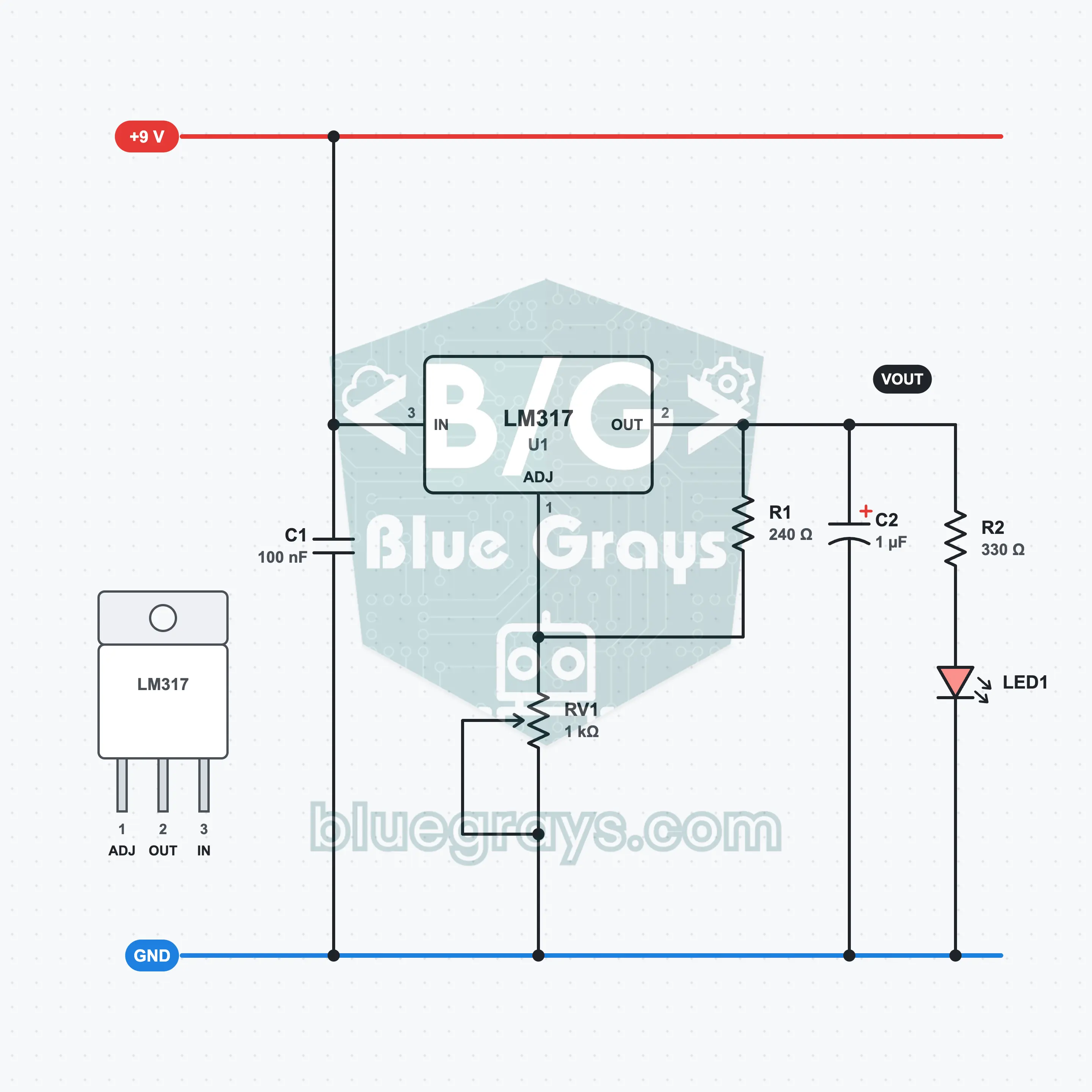
As you turn the pot, the output voltage changes between 1.25 V and about 6.5 V, and the red LED goes from off to bright. The LM317 always keeps 1.25 V between its output and its adjust pin; the ratio of two resistors sets the output. Even if the battery drops a little below 9 V, the voltage you set stays steady. You learn about the linear regulator, the adjustment formula, the dropout voltage and how excess voltage turns into heat.
Video
Elektr sxemasi
Breadboard joylashuvi
O‘rnatish qadamlari
- 1
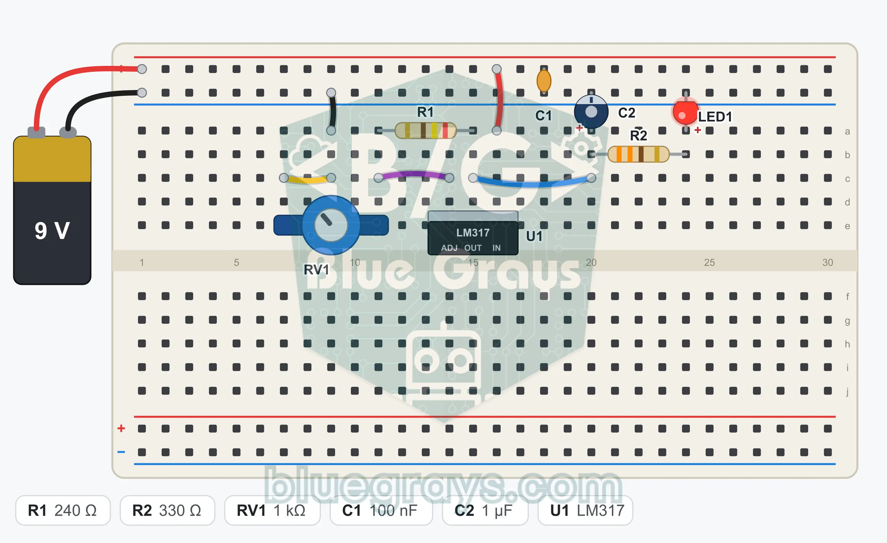
Plug the red wire of the battery clip into the top + rail and the black wire into the top GND rail at row 1. Do not connect the battery yet. This circuit uses only the top half of the breadboard and the top rails.
- 2
Take the LM317 (U1) in your hand with its printed face toward you, its metal back facing away and its legs pointing down. From left to right, pin 1 is ADJ (adjust), pin 2 is OUT (output) and pin 3 is IN (input). The metal back is connected to pin 2; it must not touch any wire or leg.
- 3
Holding U1 this way, plug it into column e with its printed face toward the center gap: pin 1 goes into e14, pin 2 into e15 and pin 3 into e16. The legs are thick; if they resist, press gently while keeping them straight.
- 4
Connect the input: plug a jumper wire from hole a of row 16 (pin 3) to the top + rail. Fit C1 (100 nF, marked 104) in row 18 between the top + rail and the top GND rail; it has no polarity.
- 5
Plug R1 (240 Ω; red, yellow, brown) into column a between row 15 (pin 2) and row 11. Plug a jumper wire from hole c of row 14 (pin 1) to hole c of row 11. This connects R1 between OUT and ADJ.
- 6
Plug RV1 (1 kΩ pot) in with its legs in column e: left leg into e7, middle leg (wiper) into e9, right leg into e11. In row 11 the right leg meets R1 and the jumper wire from pin 1.
- 7
Plug a jumper wire from hole c of row 7 to hole c of row 9 (the wiper is connected to the left leg). Plug another jumper wire from hole a of row 9 to the top GND rail. The pot now works as an adjustable resistor between ADJ and GND.
- 8
Carry the output over: plug a jumper wire from hole c of row 15 (pin 2) to hole c of row 20. From here on, row 20 carries the output voltage (VOUT).
- 9
Plug C2 (1 µF, electrolytic) with its long leg into hole a of row 20 and its short leg (the striped side of the body) into the top GND rail right above it.
- 10
Plug R2 (330 Ω; orange, orange, brown) into column b between row 20 and row 24. Plug the long leg of LED1 into hole a of row 24 and its short leg into the top GND rail right above it.
- 11
Compare the connections with the schematic: you should count 5 jumper wires, 2 resistors, 1 pot and 2 capacitors. Make sure the metal back of U1 is not touching anything, then connect the battery.
Maslahat: ulanishlarni qilayotganda batareya yoki quvvat manbaini ulama.
Sinov qadamlari
- 1
Connect the battery and slowly turn the pot from one end to the other. At one end the LED must be completely off; as you turn, it should first appear faintly and then get steadily brighter. When you turn it back, it should go out again. Which direction makes it brighter can depend on how the pot is made.
- 2
If you have a multimeter, set it to DC voltage and hold the black probe on the GND rail and the red probe on row 20. With the pot at one end you should see about 1.25 V, and at the other end about 6.5 V; in between, the voltage changes smoothly.
- 3
Move the red probe to row 16 (pin 3, IN): you see the battery voltage, between 9 V and 9.5 V with a fresh battery. Set the output to its highest value and note the difference between the two readings. If the difference falls below about 1.7 V, the output can no longer be held steady.
- 4
After running it for a few minutes, touch the body of U1: it should be slightly warm at most. In this circuit the regulator dissipates about 0.06 W at the worst setting.
Qanday ishlaydi
The LM317 always keeps 1.25 V between its output and its adjust pin (ADJ). This voltage drives about 5.2 mA through R1 (240 Ω); the same current also flows through the pot, and the voltage across the pot is added to the 1.25 V. As you turn the pot, the output changes between 1.25 V and about 6.5 V, and the LED goes from off to bright.
What does a regulator do?
The battery is 9 V, but it does not stay at exactly 9 V: when new it is close to 9.5 V, and it drops as it is used. The LM317 decides by itself how much of the input voltage to pass to the output and holds the rest across itself. So even if the battery drops from 9.5 V to 8.5 V, the output, say at 4 V, stays steady and the LED's brightness does not change. This kind of regulator is called a linear regulator.
The 1.25 V rule
The LM317 always keeps 1.25 V between its output (pin 2) and its adjust pin (pin 1). This voltage appears across R1, and 1.25 V / 240 Ω ≈ 5.2 mA flows through R1. Because very little current (≈ 50 µA) flows through the adjust pin, the same current goes on through the pot to GND. With the pot at 1 kΩ, ≈ 5.2 V appears across it and the output becomes 1.25 V + 5.2 V ≈ 6.5 V. With the pot at 0 Ω, the output drops to 1.25 V.
Why 240 Ω?
The inside of the LM317 also uses current, and this current has to flow out through the output. If no current is drawn from the output, the voltage can rise above the value you set. The manufacturer asks for at least a few milliamps to be drawn from the output (typically 3.5 mA). The 240 Ω resistor opens a 5.2 mA path even when the LED is completely off, so the output is set properly at every position of the pot.
Dropout voltage: why 6.5 V at most?
The LM317 cannot raise the output above the input, and the difference between them also has a lower limit. At the currents in this circuit, the input must be at least about 1.7 V higher than the output; the manufacturer recommends 3 V for comfortable operation. That is why the highest output you can cleanly get from a 9 V battery is around 6.5 to 7 V. The 1 kΩ pot was chosen to match this limit: when the pot reaches its end the output reaches 6.5 V, and no part of its travel is wasted.
Heat and capacitors
The difference between input and output turns into heat in the regulator: P = (Vbat − Vout) × current. In this circuit, at the worst setting (≈ 4.5 V output, ≈ 13 mA) this comes to about 0.06 W, so no heatsink is needed. C1 at the input reduces the effect of the battery wires, and C2 smooths out sudden load changes at the output. The LM317 is stable without C2 too; the manufacturer recommends both.
Haqiqat jadvali
| Pot (RV1, between ADJ and GND) | Output (VOUT) | LED current | LED1 |
|---|---|---|---|
| 0 Ω (one end) | ≈ 1.25 V | 0 mA | Off |
| 250 Ω | ≈ 2.6 V | ≈ 2 mA | Dim |
| 500 Ω | ≈ 3.9 V | ≈ 6 mA | Medium |
| 750 Ω | ≈ 5.2 V | ≈ 10 mA | Bright |
| 1 kΩ (other end) | ≈ 6.5 V | ≈ 13.6 mA | Brightest |
The values are calculated, not measured: a 1.25 V reference, a 50 µA adjust pin current and a forward voltage of 1.75 to 2 V for the red LED were assumed. Because the reference can be anywhere between 1.2 and 1.3 V depending on the chip, the highest output can come out between 6.2 and 6.8 V.
Formulalar
Output voltage
VOUT = 1.25 V × (1 + RV1 / R1) + IADJ × RV1
Misol: RV1 = 1 kΩ: 1.25 × (1 + 1000 / 240) + 50 µA × 1 kΩ ≈ 6.46 V + 0.05 V ≈ 6.5 V; RV1 = 0 Ω: 1.25 V
R1 current (minimum load)
I = 1.25 V / R1
Misol: 1.25 V / 240 Ω ≈ 5.2 mA; the minimum load current in the datasheet is typically 3.5 mA
Required battery voltage
Vbat ≥ VOUT + dropout voltage
Misol: 6.5 V + ≈ 1.7 V ≈ 8.2 V (datasheet curve, 20 mA, 25 °C); the manufacturer recommends a 3 V margin
LED current
ILED = (VOUT − VLED) / R2
Misol: (6.5 V − 2 V) / 330 Ω ≈ 13.6 mA; below 1.8 V the LED does not light
Heat in the regulator
P = (Vbat − VOUT) × (I R1 + ILED)
Misol: At the worst setting (9 V − 4.5 V) × (5.2 mA + 7.7 mA) ≈ 0.06 W; no heatsink is needed
Battery current
Ibat ≈ 1.25 V / R1 + ILED
Misol: From 5.2 mA (LED off) to ≈ 19 mA (brightest)
Ko‘p uchraydigan xatolar
The LED does not light properly at any position of the pot; at most it glows very faintly.
A 2.4 kΩ resistor (red, yellow, red) may have been fitted as R1. In that case the output rises to about 1.8 V at most and the LED barely lights. On a 240 Ω resistor the third band is brown.
When you turn the pot, the LED reaches full brightness quickly, and the rest of the pot changes nothing.
A 5 kΩ or 10 kΩ pot has been fitted instead of 1 kΩ. With 240 Ω, above about 1 kΩ the output tries to rise higher than the battery allows; only the first part of the pot is useful. Use the pot marked B1K or 102.
There is no voltage at the output (row 20), or the voltage does not follow the pot at all.
U1 may be turned around: if the printed face points toward the edge of the board, pin 1 and pin 3 swap places and the battery ends up connected to the ADJ pin. Disconnect the battery and refit U1 with its printed face toward the gap, so that from left to right the pins are ADJ, OUT, IN.
C2 bulges or gets warm.
The electrolytic capacitor is fitted backwards. Its long leg must be in row 20 (output) and its short leg, on the striped side, in the GND rail. Do not reuse an electrolytic capacitor that has been fitted backwards.
Ko‘p so‘raladigan savollar
9 V to 5 V: how is it different from the LM7805 circuit?
The 7805 gives a fixed 5 V; its pins are IN, GND and OUT. The LM317 has no GND pin; two resistors connected to the ADJ pin set the output to the value you want. Both are linear regulators and turn excess voltage into heat. The LM317 can go down to 1.25 V, while the 7805 needs at least about 7 V at its input.
The datasheet shows a 5 kΩ pot; why 1 kΩ here?
With 240 Ω and 5 kΩ the formula gives about 27 V; that is meant for a high-voltage supply. The highest output you can cleanly get from a 9 V battery is around 6.5 V. If you fit a 5 kΩ pot, only the first fifth of its rotation is useful, and beyond that the LED does not change. With 1 kΩ the whole rotation of the pot covers the range from 1.25 V to 6.5 V.
Can I connect a small DC motor instead of the LED?
For a short test yes, but the 9 V battery will struggle. Small geared motors can draw hundreds of milliamps while running and close to 1 A at startup. At 3 V and 150 mA the LM317 dissipates (9 − 3) × 0.15 ≈ 0.9 W and gets noticeably hot, and the battery runs down quickly. For longer use, use an adapter and a heatsink.
Why can't I bring the output down to 0 V?
The LM317 keeps the output 1.25 V above the ADJ pin. When the pot reaches 0 Ω, ADJ is connected to GND and the output drops to its lowest value, 1.25 V. To go lower you would need a negative supply that pulls ADJ below GND. Since the red LED does not light below 1.7 V, it goes completely dark at this end anyway.