
Capacitor: Slow-Fading LED
When you release the button, the LED should not go out at once but fade slowly over a few seconds. The part that makes this happen is the capacitor: it charges while the button is pressed and, when you release it, gives the energy it has stored back to the LED. You see with your own eyes how 1000 µF and 1 kΩ set the fade time, why an electrolytic capacitor has a polarity and what the RC time constant is.
Video
Gambar Rajah Litar
Susun Atur Breadboard
Langkah Pemasangan
- 1
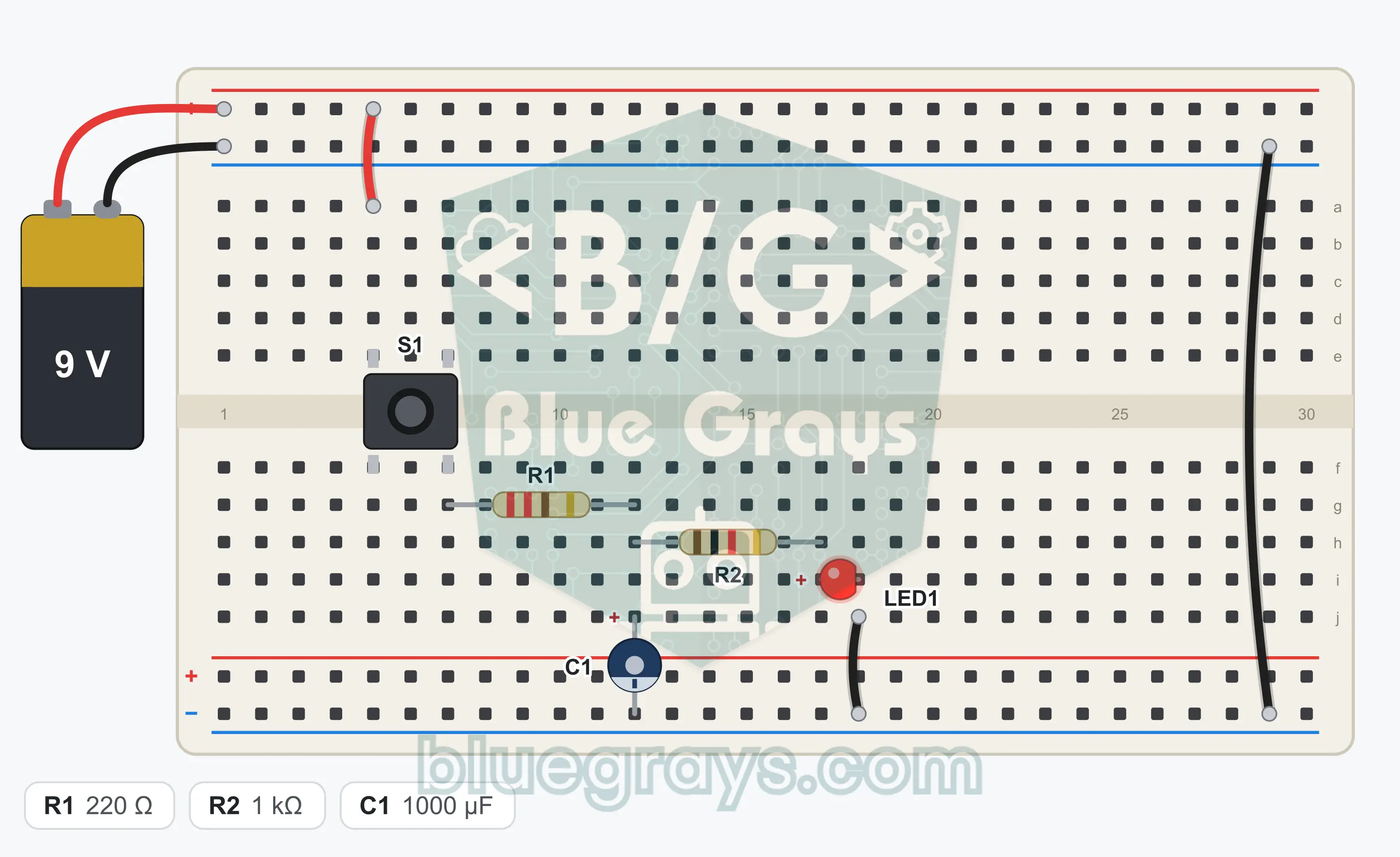
Place the S1 button over the center gap: its left legs go into row 5 and its right legs into row 7. Push the button down until it is fully seated.
- 2
Connect the top + rail to the top half of row 5 with a jumper wire. This is the row of the button's top left leg.
- 3
Plug one leg of R1 (220 Ω; red, red, brown) into the bottom half of row 7, that is, the row of the button's bottom right leg, and the other leg into row 12 in the bottom half.
- 4
Look at the legs of C1: the long leg is positive (+), the striped side of the body is negative (−). An electrolytic capacitor is damaged if it is fitted backwards, so do not mix up the direction.
- 5
Plug the long (+) leg of C1 into the bottom half of row 12 and the (−) leg on the striped side into the bottom GND (−) rail.
- 6
Plug one leg of R2 (1 kΩ; brown, black, red) into row 12 in the bottom half and the other leg into row 17.
- 7
Plug the long leg of LED1 into row 17 in the bottom half and the short leg into row 18.
- 8
Connect the bottom half of row 18 to the bottom GND (−) rail with a jumper wire.
- 9
Connect the top GND rail to the bottom GND rail with a jumper wire (at the right end of the breadboard, level with row 29). Because the battery will be connected to the top rails, the bottom rail becomes GND through this bridge.
- 10
Plug the red wire of the battery clip into the top + rail and the black wire into the top GND (−) rail. Compare the connections with the schematic once, then snap the battery onto the clip.
Petua: biarkan bateri atau bekalan kuasa tidak disambung semasa membuat pendawaian.
Langkah Ujian
- 1
Connect the battery and do not touch the button: LED1 stays off.
- 2
Press S1 and hold it for two seconds: the LED lights immediately.
- 3
Release the button: the LED does not go out at once, it fades slowly in about three to four seconds.
- 4
Tap the button very briefly and let go: because the capacitor is not fully charged, the LED lights more dimly and goes out sooner.
Cara Ia Berfungsi
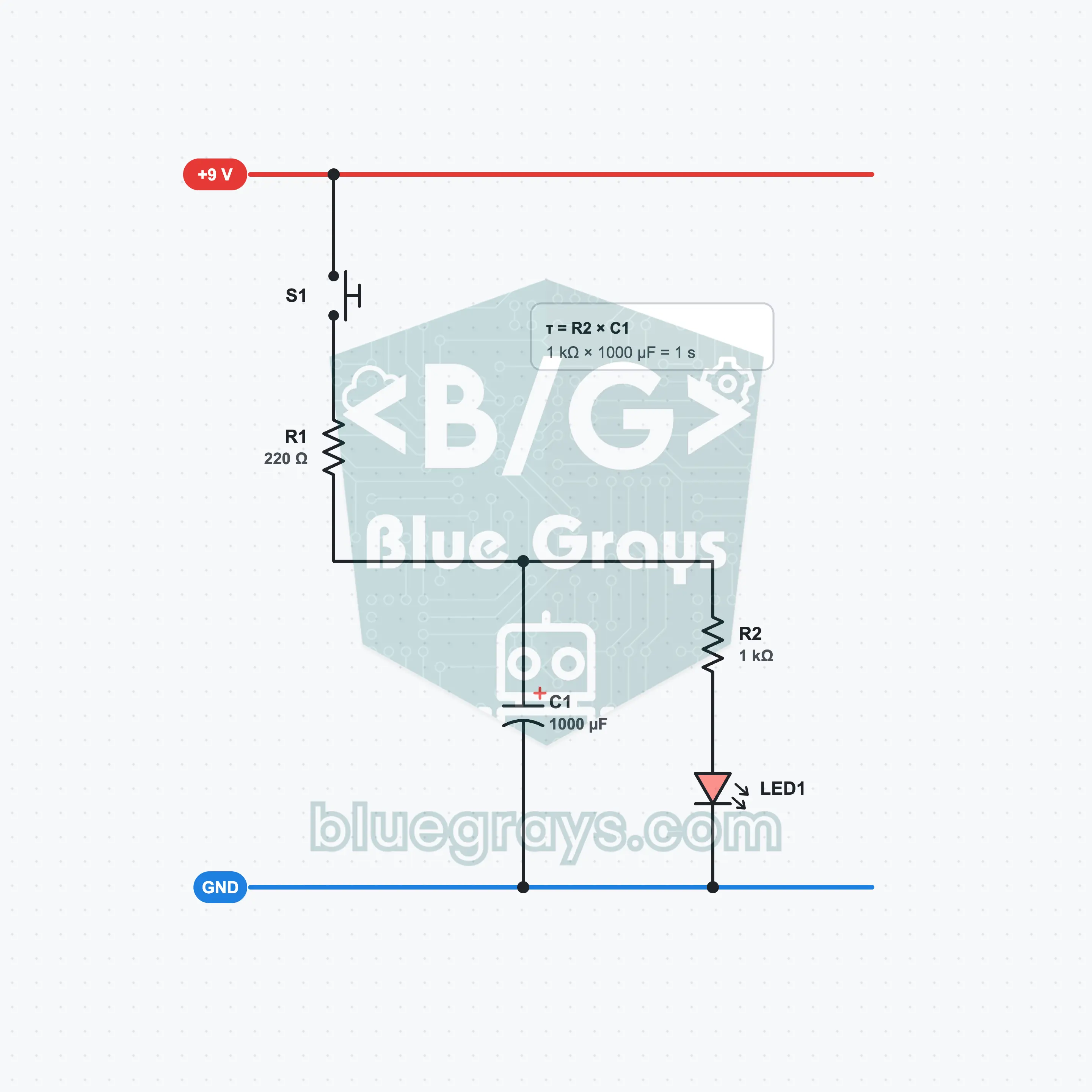
When you press the button C1 charges and the LED lights. When you release the button C1 discharges through R2; the LED fades out slowly in about three to four seconds.
A capacitor stores energy
Inside a capacitor there are two conductive surfaces that do not touch each other. When a voltage is applied, charge builds up on these surfaces; when the voltage is removed, the charge stays there. C1 is like a small tank: it fills while the button is pressed and empties when you release it.
Charging
When you press the button, current passes through R1 and splits into two paths: part of it charges C1, part of it lights the LED through R2. C1 charges in about one fifth of a second and its voltage settles at about 7.7 V. During this time the LED lights with 5.7 mA.
Discharging
When you release the button, the path from the battery is cut; the only source powering the LED is now C1. As the capacitor discharges through R2 and the LED, its voltage drops, the current decreases and the LED dims. When the voltage gets close to 2 V the LED goes out; about 2 V stays inside C1.
RC time constant
The speed of the discharge is set by the product of R2 and C1: 1 kΩ × 1000 µF = 1 second. Every second the current falls to about one third. This is why the LED dims quickly at first, then more and more slowly, and after three to four seconds can no longer be seen by eye.
Formula
Time constant (discharge)
τ = R2 × C1
Contoh: 1 kΩ × 1000 µF = 1 s
LED current (S1 pressed)
I = (Vbat − VLED) / (R1 + R2)
Contoh: (9 V − 2 V) / (220 Ω + 1 kΩ) ≈ 5.7 mA
C1 voltage (S1 pressed)
VC = Vbat − I × R1
Contoh: 9 V − 0.0057 A × 220 Ω ≈ 7.7 V
Initial charging current
I = Vbat / R1
Contoh: 9 V / 220 Ω ≈ 41 mA; only at the first instant, then it drops quickly
LED current while fading
I(t) = I0 × e^(−t / τ)
Contoh: After 1 s, 5.7 mA × 0.37 ≈ 2.1 mA; after 3 s ≈ 0.3 mA
Kesilapan Lazim
The LED goes out immediately when you release the button.
C1 is not fitted, is in the wrong row or its value is too small. Its positive leg must be in row 12, where R1 and R2 meet.
The capacitor heats up.
C1 is fitted backwards. Disconnect the battery; turn its long leg to row 12 and its striped side to the GND rail.
The LED lights without the button being pressed and never goes out.
The + jumper wire and R1 are plugged into the row with the same number, so the button is bypassed. The jumper wire must be in the top half of row 5, R1 in the bottom half of row 7.
The LED fades slowly but the time is very short.
The two resistors have been mixed up: if 220 Ω is fitted in place of R2, the time constant drops to 0.22 s. The 1 kΩ must be between C1 and the LED.
Soalan Lazim
Does a capacitor work like a small battery?
Both store energy, but in very different amounts. The capacitor in this circuit can power the LED for only a few seconds; a 9 V battery lights the same LED for days. The advantage of a capacitor is that it can charge and discharge very quickly. That is why it is used for timing, smoothing and short-term energy backup.
What happens if I fit the electrolytic capacitor backwards?
An electrolytic capacitor is polarized. If it is connected backwards, current leaks through it, it heats up, swells and can burst. The long leg is positive; the stripe with the minus sign on the body marks the negative leg. Always check the direction before connecting the battery, and make sure the voltage printed on it is at least 16 V.
How do I make the fade time longer?
The time is set by the product of R2 and C1. If you make the capacitor larger, for example by fitting 2200 µF, or if you increase R2, the LED fades more slowly. Increasing R2 also lowers the highest brightness of the LED; making the capacitor larger does not change the brightness, it only makes the time longer.
What does R1 do, can't I leave it out?
An empty capacitor behaves like a short circuit at the first instant and draws a very high current. R1 limits this initial current to about 41 mA; this way the button contacts and the battery are not stressed. The capacitor still charges in a time as short as one fifth of a second, so you do not notice the delay.