
Dim an LED with a Potentiometer
Set the brightness of an LED by turning a shaft. A potentiometer is an adjustable resistor: as you turn the shaft its resistance changes between 0 and 10 kΩ, and the current through the LED changes with it. By building it, you learn why a fixed resistor is always added next to the pot and which two of the three legs are used.
Video
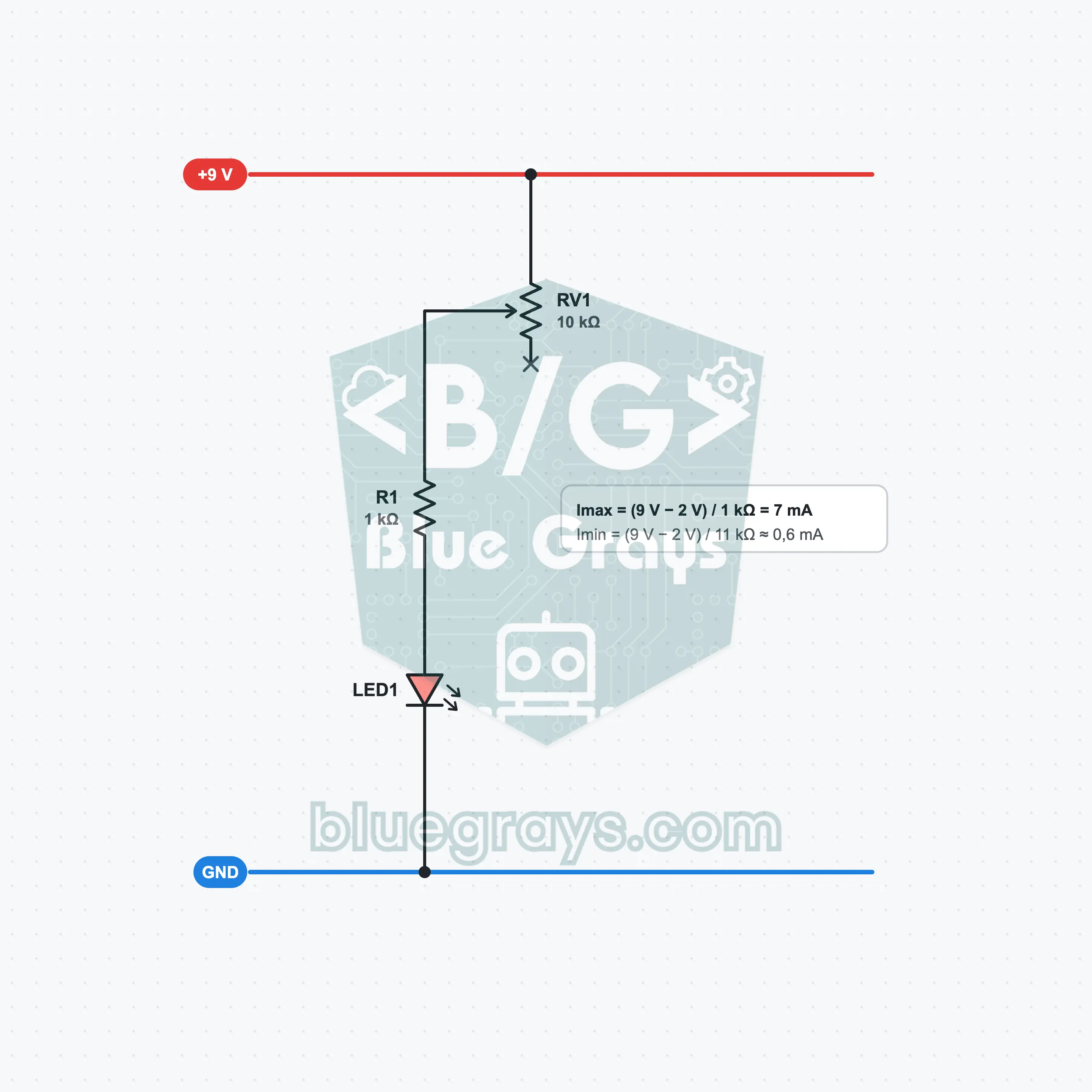
Gambar Rajah Litar
Susun Atur Breadboard
Langkah Pemasangan
- 1
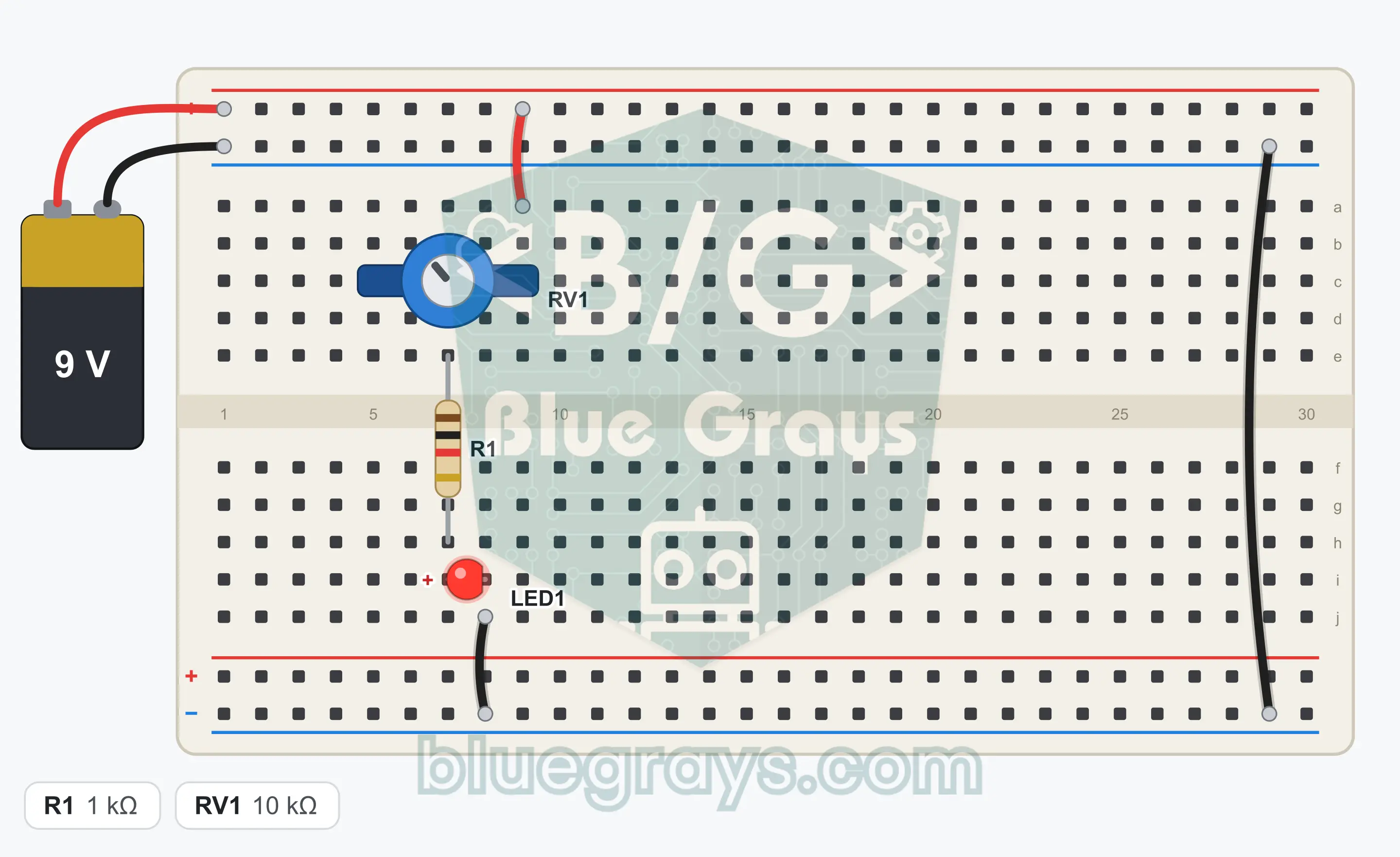
Place the RV1 potentiometer in the top half above the gap: its three legs go into rows 5, 7 and 9. The legs sit with one row skipped between them. Push the pot down until it is fully seated.
- 2
Get to know the legs: the middle leg (row 7) is the wiper, and the two legs on the sides are the ends of the resistive track. In this circuit the end leg in row 9 and the middle leg are used; the leg in row 5 is left unconnected.
- 3
Connect the top + rail to the top half of row 9 with a jumper wire.
- 4
Plug one leg of R1 (1 kΩ; brown, black, red) into the top half of row 7 and the other leg into the bottom half of row 7. The resistor crosses over the center gap like a bridge.
- 5
Plug the long leg of LED1 into the bottom half of row 7, the same row as the leg of R1.
- 6
Plug the short leg of LED1 into row 8 in the bottom half.
- 7
Connect the bottom half of row 8 to the bottom GND (−) rail with a jumper wire.
- 8
Connect the top GND rail to the bottom GND rail with a jumper wire (at the right end of the breadboard, level with row 29). Because the battery will be connected to the top rails, the bottom rail becomes GND through this bridge.
- 9
Set the shaft of the pot to about the middle position.
- 10
Plug the red wire of the battery clip into the top + rail and the black wire into the top GND (−) rail. Compare the connections with the schematic once, then snap the battery onto the clip.
Petua: biarkan bateri atau bekalan kuasa tidak disambung semasa membuat pendawaian.
Langkah Ujian
- 1
Connect the battery: LED1 must light dimly.
- 2
Turn the shaft slowly in one direction: the LED gets brighter or dimmer. When you turn it the other way, the opposite happens.
- 3
Turn the shaft all the way to the bright end: the LED reaches its brightest and stays steady there. Thanks to R1 the current does not go above 7 mA.
- 4
Turn the shaft all the way to the other end: the LED gets very dim but does not go out completely.
Cara Ia Berfungsi
The potentiometer is an adjustable resistor in series with the LED. As you turn the shaft the total resistance changes between 1 kΩ and 11 kΩ, and the LED current moves between 7 mA and 0.6 mA.
Inside the pot
Between the two end legs of the pot there is an arc-shaped 10 kΩ resistive track. The middle leg travels along this track with a wiper attached to the shaft. As you turn the shaft, the part of the track between the wiper and the end leg gets longer or shorter; the resistance changes between 0 and 10 kΩ.
Series resistances add up
The pot and R1 are connected one after the other, so their resistances add up. The current is found with the formula (9 V − 2 V) / (RV1 + R1). As the pot's resistance grows, the total resistance grows, the current shrinks and the LED dims.
Protective resistor
When the pot's resistance falls to zero, only R1 is left in the circuit and the current is 7 mA. Without R1 there would be nothing left to limit the LED at that moment. An adjustable resistor always gets a fixed resistor next to it that limits the current even in the worst case.
Brightness does not change in equal steps
With the pot exactly in the middle the total resistance is 6 kΩ and the current is about 1.2 mA; that is one sixth of the highest current. Most of the change in current is gathered at the bright end of the rotation. Because the eye picks out differences at small currents well, the LED still seems to dim smoothly.
Formula
LED current
I = (Vbat − VLED) / (RV1 + R1)
Contoh: Pot in the middle: (9 V − 2 V) / (5 kΩ + 1 kΩ) ≈ 1.2 mA
Highest current (RV1 = 0 Ω)
Imax = (Vbat − VLED) / R1
Contoh: (9 V − 2 V) / 1 kΩ = 7 mA
Lowest current (RV1 = 10 kΩ)
Imin = (Vbat − VLED) / (RV1 + R1)
Contoh: (9 V − 2 V) / (10 kΩ + 1 kΩ) ≈ 0.64 mA
Kesilapan Lazim
The brightness does not change, the LED is always the same.
R1 is connected to an end leg of the pot, not to the middle leg. The top leg of R1 must be in row 7.
The LED does not light.
R1 does not join the two sides of the gap, or the bottom GND bridge is missing.
The LED is very bright, the pot heats up.
R1 has been skipped and the pot is connected directly to the LED. Disconnect the battery right away and fit R1 between the middle leg and the LED.
The LED is always dim.
10 kΩ or 100 kΩ is fitted instead of R1. The colors must be brown, black, red.
Soalan Lazim
Why is the third leg of the pot left unconnected?
Inside the pot there is a 10 kΩ resistive track between the two end legs, and on the middle leg a wiper that travels along this track. To adjust the current, the wiper and one of the ends are enough. You will see the voltage divider connection, where all three legs are used together, in later circuits of the series.
Can't I dim the LED with the pot alone, without R1?
It dims, but it is not safe. When you turn the shaft all the way to the end, the pot's resistance falls to zero. At that moment the LED is connected to the 9 V battery with no resistance; both the LED and the thin resistive track inside the pot can burn out. R1 stays in the circuit whatever position the pot is in and limits the current to 7 mA at most.
Why doesn't the LED go out completely?
When the pot is at its highest value the total resistance is 11 kΩ and about 0.6 mA still flows through the LED. LEDs give visible light even at a current this small. To turn the LED off completely you need to cut the current, that is, add a button or a switch to the circuit.
Why does the brightness change so fast at one end of the rotation?
The current is inversely proportional to the total resistance. When the total resistance rises from 1 kΩ to 2 kΩ the current drops to half; that is only one tenth of the rotation. Over the rest of the rotation, as the resistance rises from 2 kΩ to 11 kΩ, the current falls much more slowly. This is why most of the change is squeezed into the bright end.