
EL-54IntermediatePremiumLogic gate circuits
Gate Flasher: A Schmitt Oscillator with the 74HC14
Make your own clock signal with a single logic gate, one resistor and one capacitor. Thanks to its two separate thresholds, the Schmitt-trigger NOT gate inside the 74HC14 oscillates by itself as C1 charges and discharges; LED1 and LED2 blink in turn about once a second. You see hysteresis with your own eyes and learn why an ordinary NOT gate cannot do this job.
0.0(0)
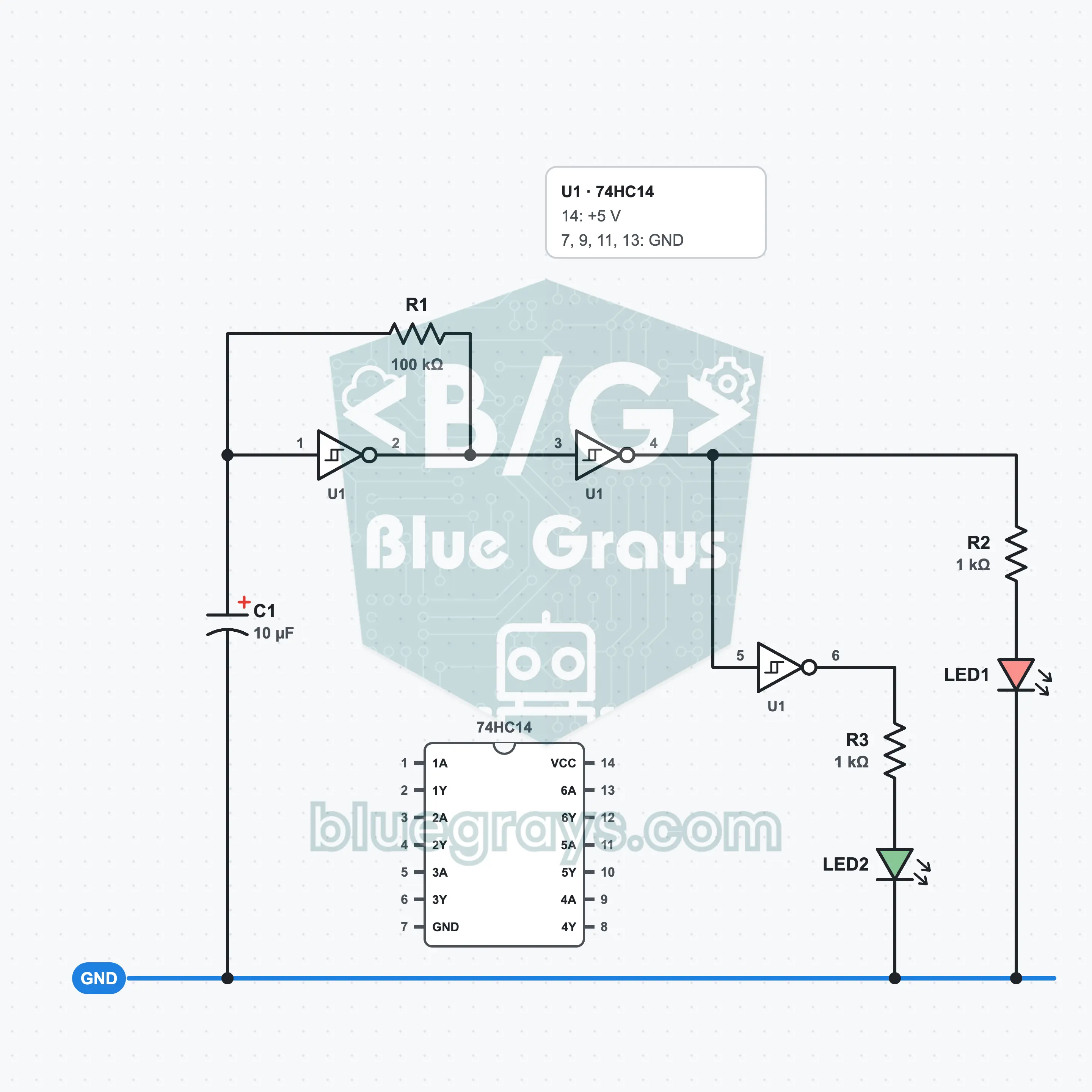
It is built on a half-size breadboard with a 5 V supply, one 74HC14, three resistors, one capacitor and two LEDs. The first gate of U1 is a square-wave oscillator with R1 and C1: the output charges and discharges C1, and the input moves back and forth between two thresholds. The second and third gates buffer this signal, and LED1 and LED2 light in turn. What you learn: the Schmitt trigger, hysteresis, timing with an RC, calculating frequency and making a clock signal with logic gates.
Premium Content
This circuit's build steps, how-it-works guide and FAQ are open to Premium members.
- Build Steps
- How It Works
- Frequently Asked Questions