
EL-53IntermediatePremiumLogic gate circuits
2-to-4 Decoder: Two Addresses, Four Outputs
Pick just one of four LEDs with two buttons. The 74HC04 inverts the two address inputs, and the four AND gates of the 74HC08 each open a separate output for one address: LED1 lights at 00, LED2 at 01, LED3 at 10, LED4 at 11. This address decoding method is the basis of how computers select the right memory cell and the right chip in a circuit.
0.0(0)
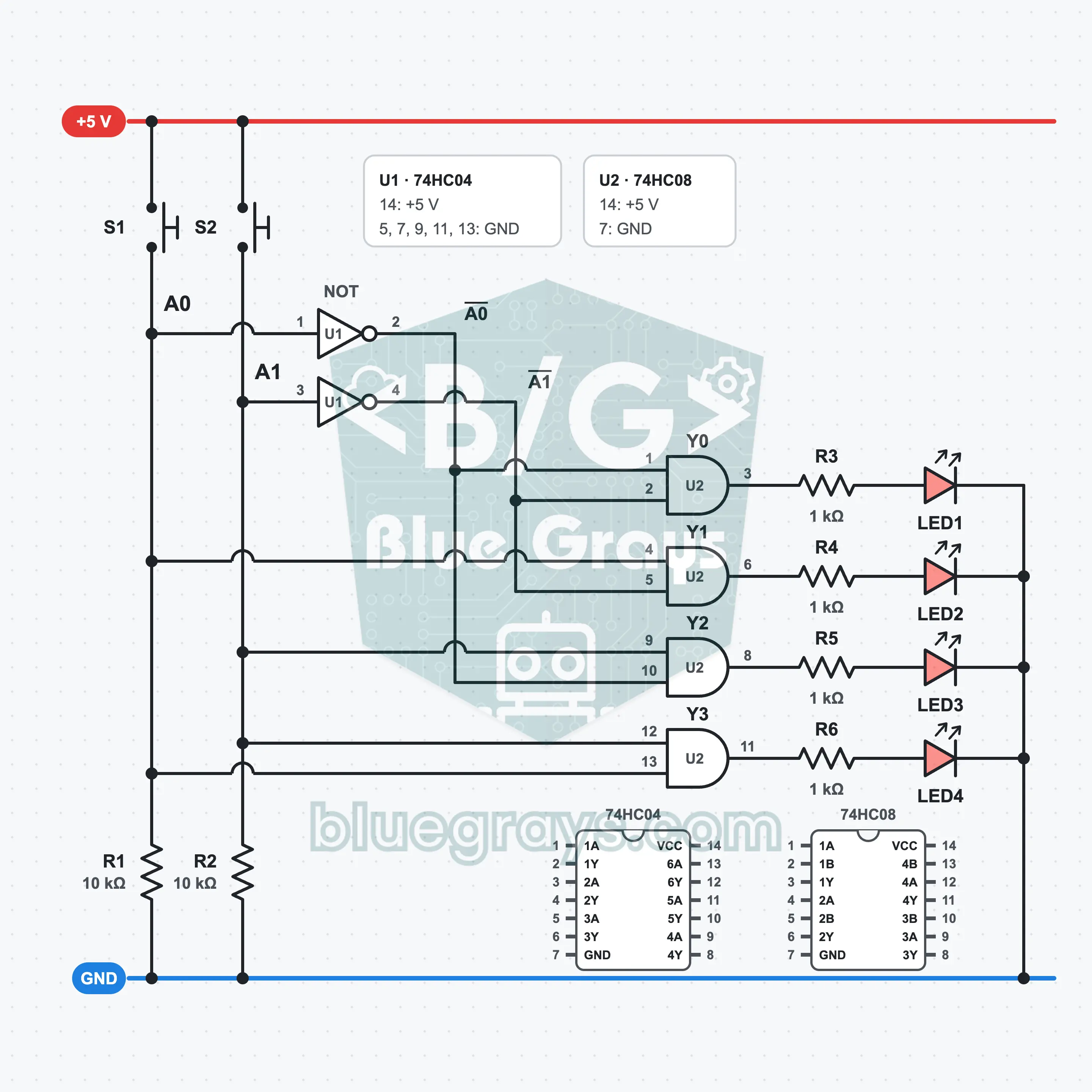
It is built on a full-size breadboard with a 5 V supply, one 74HC04, one 74HC08, two buttons, six resistors and four LEDs. S1 is address input A0 and S2 is address input A1. The 74HC04 produces the inverse of the two inputs; each AND gate of the 74HC08 gives 1 for only one of the four combinations and lights its own LED. Two of the gates are in the top row of the IC, so three signals have to cross to the other side of the gap. What you learn: address decoding, selecting a single output with a binary number, using all four gates of the 74HC08, the logic of memory and chip selection.
Premium Content
This circuit's build steps, how-it-works guide and FAQ are open to Premium members.
- Build Steps
- How It Works
- Frequently Asked Questions