
EL-51IntermediatePremiumLogic gate circuits
Combination Lock: A Code Circuit with Four Switches
Set a code with four slide switches: when the right combination (1-0-1-1) is entered, the green LED lights, and for the other 15 combinations the red LED does. The 74HC04 inverts the 0 in the code, and the 74HC08 ANDs the four bits in two stages. The red LED is the inverse of the lock output. In the task you also learn which NOT gate to plug in or remove to change the code.
0.0(0)
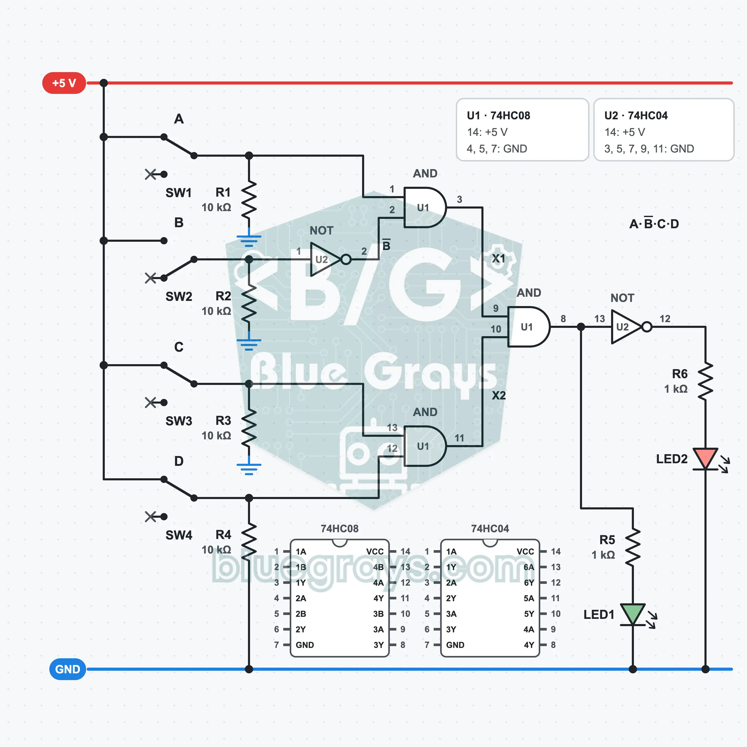
It is built on a full-size breadboard with a 5 V supply, one 74HC08, one 74HC04, four slide switches, six resistors and two LEDs. The switches make up a four-bit code. A bit that is 0 in the code first passes through a NOT gate, then the four bits are combined with a two-stage AND. If the result is 1 the green LED is on, if it is 0 the red LED is on. What you learn: catching a specific combination, building a 4-input AND from 2-input gates, flipping a bit with NOT, and the 16 combinations.
Premium Content
This circuit's build steps, how-it-works guide and FAQ are open to Premium members.
- Build Steps
- How It Works
- Frequently Asked Questions