
LED and Resistor: Your First Circuit
This is where electronics starts: build your first circuit with a 9 V battery, a resistor and an LED. No code, no board. On your own breadboard you see why an LED lights in only one direction, why the resistor is a must and how the 470 Ω value is calculated. Here you learn the current limiting calculation you will use in every circuit that follows.
Video
Circuit Diagram
Breadboard Layout
Build Steps
- 1
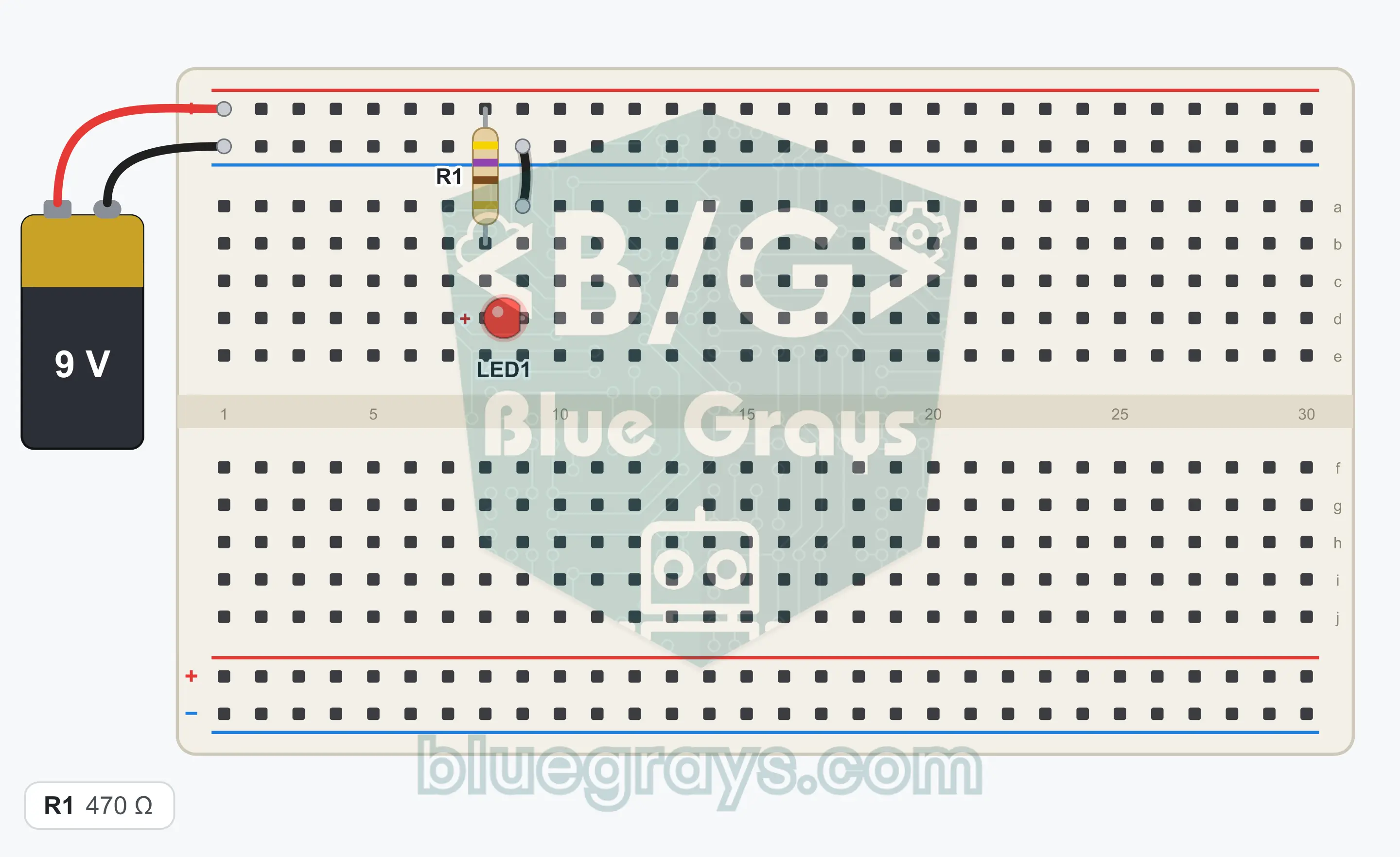
Place the breadboard in front of you. The rails marked + and − along the long edges are connected from end to end. In the numbered rows in the middle, the five holes on the same side of the gap are connected to each other.
- 2
Look at the legs of LED1: the long leg is the anode (+), the short leg is the cathode (−). The flat edge of the body also marks the cathode side.
- 3
Get R1 ready (470 Ω; its colors are yellow, violet, brown) and bend its two legs downward. A resistor has no direction, it can be fitted either way.
- 4
Plug one leg of R1 into the top + rail and the other leg into row 8 above the gap.
- 5
Plug the long leg of LED1 into row 8, that is, the same row as the leg of R1.
- 6
Plug the short leg of LED1 into row 9 right next to it. The two legs must not go into the same row.
- 7
Connect row 9 to the top GND (−) rail with a jumper wire.
- 8
Plug the red wire of the battery clip into the top + rail and the black wire into the top GND (−) rail. Compare the connections with the schematic once, then snap the battery onto the clip.
Tip: keep the battery or power supply disconnected while wiring.
Test Steps
- 1
The moment you snap the battery onto the clip, LED1 must light and stay on steadily without flickering.
- 2
Pull out the end of the jumper wire that is in the GND rail: the circuit opens and the LED goes out. When you plug it back in, it lights again.
- 3
After half a minute, touch R1 and the LED with your finger: neither should have warmed up.
How It Works
A 9 V battery lights a red LED with about 15 mA through a 470 Ω resistor. The resistor limits the current, and the LED lights only when it is fitted the right way around.
Closed circuit
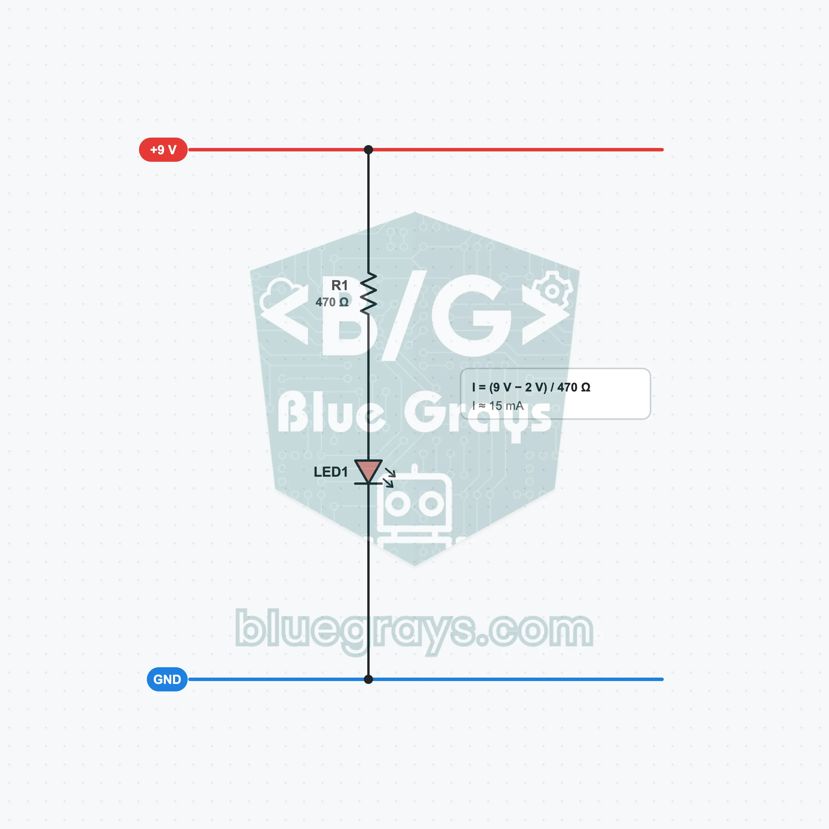
Current flows only if it finds an unbroken path that leaves the positive terminal of the battery and returns to the negative terminal. In this circuit the path is: the + rail, R1, LED1, the jumper wire and the GND rail. If you open the path anywhere, the current stops and the LED goes out.
An LED conducts in one direction
An LED is a diode: it lets current pass only from the anode to the cathode. While a red LED is lit, about 2 V stays across it. If it is fitted backwards, no current passes and the LED does not light.
The resistor limits the current
The battery gives 9 V, and the LED uses 2 V of that. The remaining 7 V drops across the resistor. According to Ohm's law, with 7 V across 470 Ω the current is about 15 mA. The larger the resistor, the smaller the current and the dimmer the LED.
Inside the breadboard
Under the holes there are metal strips. Legs plugged into the same strip are connected to each other as if they were soldered. Because R1 and the long leg of LED1 share the strip of row 8, no wire is needed between them.
Formulas
Resistor calculation
R = (Vbat − VLED) / I
Example: (9 V − 2 V) / 0.015 A ≈ 467 Ω; the nearest standard value is 470 Ω
LED current
I = (Vbat − VLED) / R1
Example: (9 V − 2 V) / 470 Ω ≈ 15 mA
Power dissipated in the resistor
P = I × I × R1
Example: 0.015 A × 0.015 A × 470 Ω ≈ 0.1 W; a 1/4 W resistor is easily enough
Common Mistakes
The LED does not light.
The LED is fitted backwards. The long leg must be in the same row as R1, the short leg in the row that goes to GND.
The LED does not light, and its direction is correct.
Both legs of the LED are in the same five-hole row. The legs must sit in two separate rows, side by side.
The LED is very dim.
4.7 kΩ or 47 kΩ is fitted instead of 470 Ω. Read the color bands again: yellow, violet, brown.
The LED flashed for a moment and went out.
The LED was connected without a resistor and burned out. One leg of R1 must be in the + rail, the other in the LED's row.
FAQ
What happens if I connect the LED without a resistor?
An LED cannot limit its own current. The moment the voltage across it goes slightly above 2 V, the current rises very quickly. An LED connected directly to a 9 V battery lights very brightly for a brief moment, then fails. The resistor takes the remaining 7 V of the battery and keeps the current at a safe value.
Should I put the resistor before or after the LED?
It makes no difference. The resistor and the LED are in series, and the same current flows through every part connected in series. Whether you put the resistor between the + rail and the LED or between the LED and GND, the current is still 15 mA. What matters is that the two sit one after the other on the same path.
Why 470 Ω? Can't I use a smaller resistor?
The current a 5 mm LED can carry continuously is usually 20 mA. On a 9 V battery, 470 Ω gives about 15 mA; that is both bright and safe. If you fit 220 Ω, the current rises to 32 mA and the life of the LED gets shorter. With 1 kΩ, 7 mA flows; the LED dims a little but the battery lasts longer.
How long does a 9 V battery run this circuit?
The capacity of an alkaline 9 V battery is roughly 500 mAh. Since the circuit draws 15 mA, the battery lasts about 30 hours. As time passes the battery voltage drops and the LED slowly dims. When you are not using the circuit, taking the battery off the clip is enough.