
Series and Parallel LEDs
Connect three LEDs in two different ways and see the difference on the same breadboard. Two LEDs are wired in series and share a single resistor; the third LED sits in parallel with them, with its own resistor. You test for yourself, by pulling one LED out, that in the series branch the current stays the same and the voltage is shared, and that in the parallel branch each LED works independently.
Video
Circuit Diagram
Breadboard Layout
Build Steps
- 1
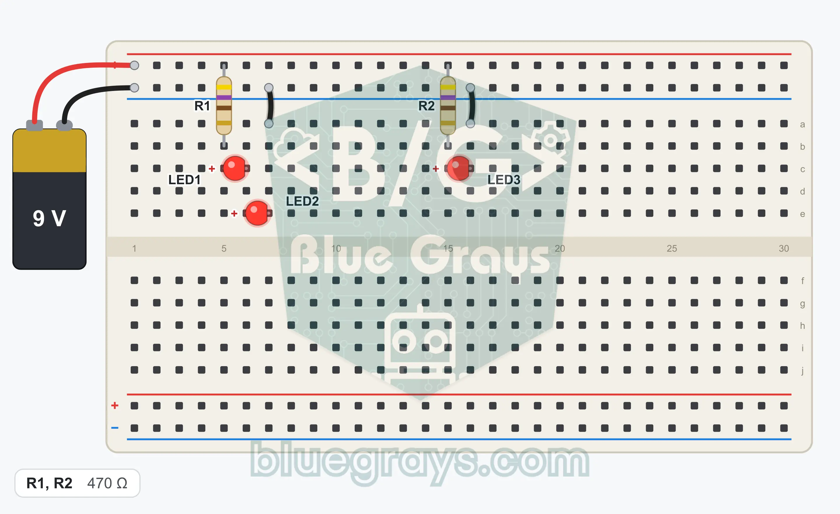
Build the series branch first. Plug one leg of R1 (470 Ω; yellow, violet, brown) into the top + rail and the other leg into row 5 above the gap.
- 2
Plug the long leg of LED1 into row 5 and the short leg into row 6.
- 3
Plug the long leg of LED2 into row 6, that is, the same row as the short leg of LED1. Plug its short leg into row 7.
- 4
Connect row 7 to the top GND (−) rail with a jumper wire. The series branch is complete: + rail, R1, LED1, LED2, GND.
- 5
Now build the parallel branch. Plug one leg of R2 (470 Ω) into the top + rail and the other leg into row 15 above the gap.
- 6
Plug the long leg of LED3 into row 15 and the short leg into row 16.
- 7
Connect row 16 to the top GND (−) rail with a jumper wire. Because both branches are connected to the same + and GND rails, they are in parallel with each other.
- 8
Plug the red wire of the battery clip into the top + rail and the black wire into the top GND (−) rail. Compare the connections with the schematic once, then snap the battery onto the clip.
Tip: keep the battery or power supply disconnected while wiring.
Test Steps
- 1
Connect the battery: all three LEDs must light at once. LED1 and LED2 look the same as each other, and LED3 looks slightly brighter than them.
- 2
Pull LED1 out: LED2 goes out too, LED3 stays on. Plug LED1 back in the same direction.
- 3
Pull LED3 out: LED1 and LED2 are not affected at all. Plug LED3 back in.
- 4
Pull out the GND jumper wire at row 7: only the series branch goes out. Plug the jumper wire back in.
How It Works
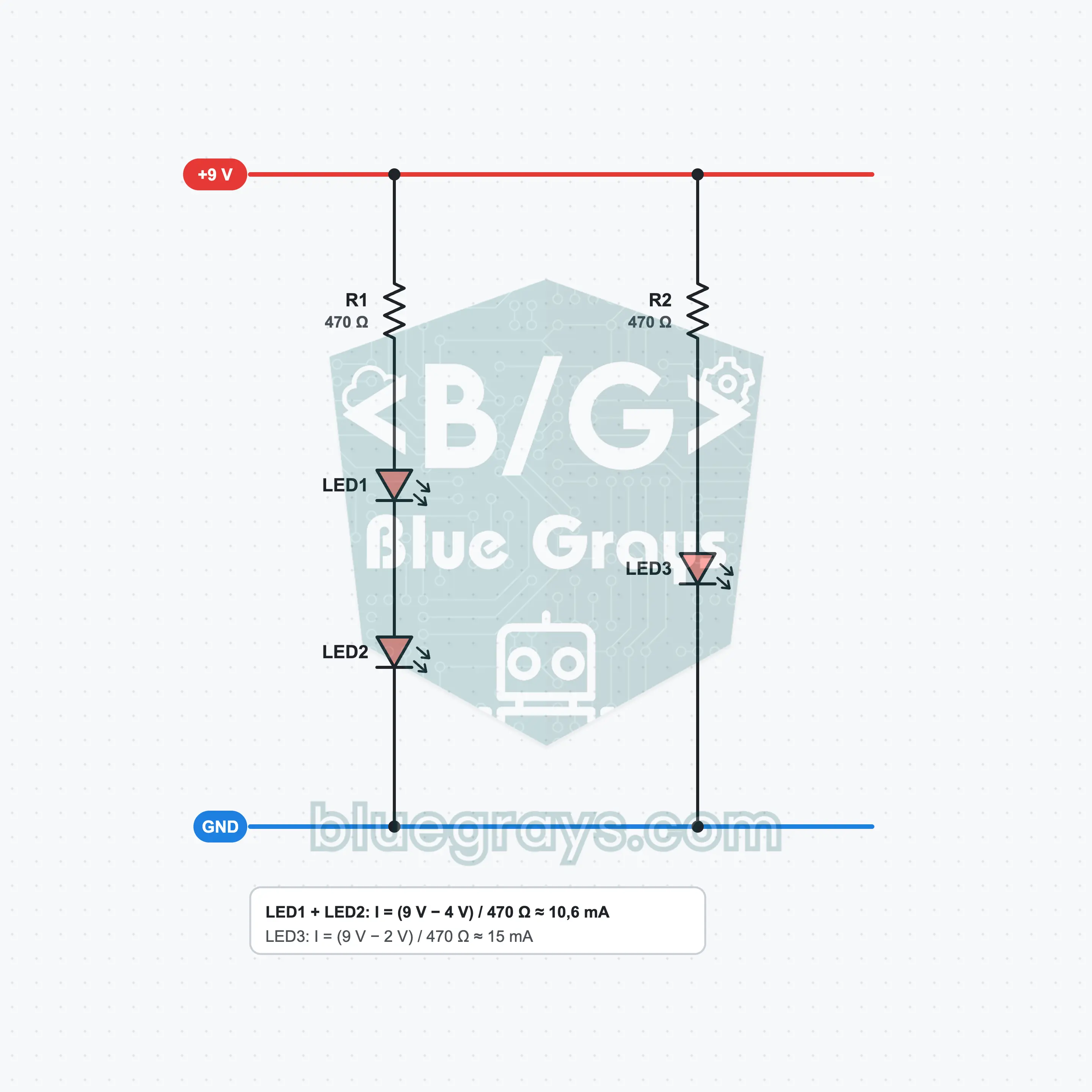
LED1 and LED2 are wired in series and share R1; LED3 sits in the parallel branch with its own resistor R2. In the series branch the current is shared, and the parallel branches work independently of each other.
Series: one path, shared current
R1, LED1 and LED2 are lined up one after the other; there is no other path the current can take. So the same current flows through all three and the two LEDs light at the same brightness. The voltage, however, is shared: each LED takes 2 V and the remaining 5 V drops across the resistor.
Parallel: separate paths, shared voltage
The series branch and the LED3 branch are connected to the same two rails, so there is 9 V across both of them. Each branch sets its own current with its own resistor. Removing one branch does not change the voltage or the current of the other.
Total current drawn from the battery
The currents of parallel branches add up. About 10.6 mA flows through the series branch and about 14.9 mA through the LED3 branch; the battery supplies the sum of the two, 25.5 mA. The more parallel branches you add, the faster the battery runs down.
Why the series branch is dimmer
Both resistors are 470 Ω, but the voltage across them is different. In the series branch the LEDs use 4 V, so 5 V is left for the resistor; in the parallel branch 7 V is left. With the same resistor, less voltage means less current; this is why LED1 and LED2 are slightly dimmer.
Formulas
Series branch current
I1 = (Vbat − VLED1 − VLED2) / R1
Example: (9 V − 2 V − 2 V) / 470 Ω ≈ 10.6 mA
Parallel branch current
I2 = (Vbat − VLED3) / R2
Example: (9 V − 2 V) / 470 Ω ≈ 15 mA
Total current
I = I1 + I2
Example: 10.6 mA + 14.9 mA = 25.5 mA
Number of LEDs in series
n × VLED < Vbat
Example: 3 × 2 V = 6 V is fine; 5 × 2 V = 10 V is over 9 V, so five LEDs do not light
Common Mistakes
Neither of the two LEDs in the series branch lights.
LED1 or LED2 is fitted backwards. In the series branch a single reversed LED turns off the whole branch.
Only LED1 lights, LED2 is off.
Both legs of LED2 are in the same row, or the GND jumper wire is plugged into row 6. The jumper wire must be in row 7.
LED3 does not light.
R2 and the long leg of LED3 are not in the same row (row 15), or the GND jumper wire at row 16 is missing.
FAQ
Why does the other LED go out when I pull out one of the LEDs in series?
In a series connection there is only one path the current can follow, and that path runs through all the parts. When you pull out one of the LEDs, the path breaks at that point, the current stops completely and the other LED in the same branch goes out too. This is why, on old-style holiday lights, all of them go out when one bulb burns out.
Isn't a single resistor enough for parallel LEDs?
It is not recommended. The forward voltages of two LEDs are never exactly the same; the one with the slightly lower voltage pulls most of the current, lights brighter and heats up more. When you give each branch its own resistor, the current of each LED is set by its own resistor and the branches do not affect each other.
What is the largest number of red LEDs I can connect in series on a 9 V battery?
Each red LED needs about 2 V. Three LEDs use 6 V and 3 V is left for the resistor; this works comfortably. Four LEDs need 8 V, only 1 V is left for the resistor, and the LEDs go out when the battery weakens a little. Because blue or white LEDs need 3 V, at most two of them can be connected in series.
Which one uses less battery, series or parallel?
The series connection. In the series branch the two LEDs share the same 10.6 mA. If you connected the same two LEDs in parallel with separate resistors, each would draw 15 mA, 30 mA in total. In a series connection the battery voltage is spent as light in the LEDs instead of turning into heat in the resistor.