
Light an LED with a Push Button
Add a push button to your first circuit: the LED lights when you press it and goes out when you release it. A button is like a bridge; pressing it completes the path, releasing it opens the path. You feel the difference between an open circuit and a closed circuit at your fingertip. You also learn which legs of a four-leg button are connected inside and how it sits on the breadboard.
Video
Circuit Diagram
Breadboard Layout
Build Steps
- 1
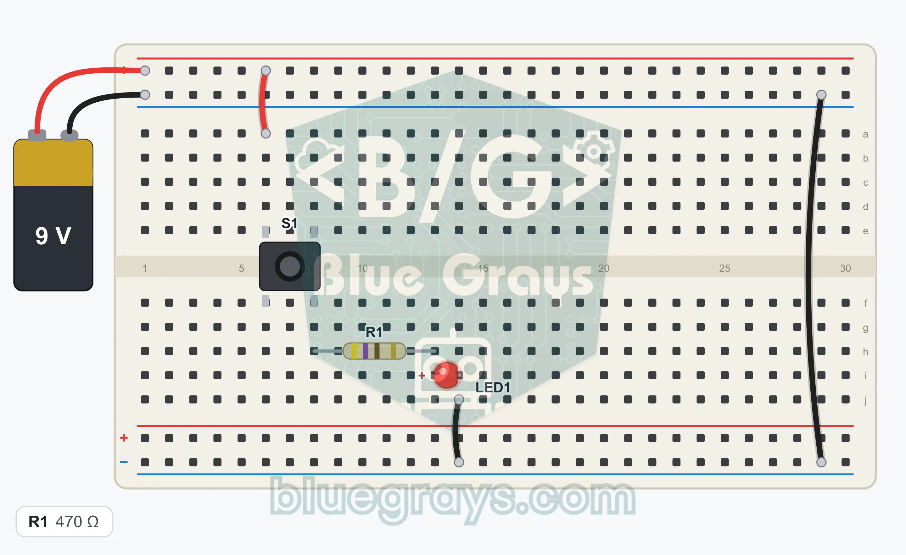
Place the S1 button over the center gap: its left legs go into row 6 and its right legs into row 8. Two legs stay in the top half, two legs in the bottom half. Push the button down until it is fully seated.
- 2
Connect the top + rail to the top half of row 6 with a jumper wire. This is the row of the button's top left leg.
- 3
Plug one leg of R1 (470 Ω; yellow, violet, brown) into the bottom half of row 8, that is, the row of the button's bottom right leg.
- 4
Plug the other leg of R1 into row 13 in the bottom half.
- 5
Plug the long leg of LED1 into row 13 in the bottom half, the same row as the leg of R1.
- 6
Plug the short leg of LED1 into row 14 right next to it.
- 7
Connect the bottom half of row 14 to the bottom GND (−) rail with a jumper wire.
- 8
Connect the top GND rail to the bottom GND rail with a jumper wire (at the right end of the breadboard, level with row 29). Because the battery will be connected to the top rails, the bottom rail becomes GND through this bridge.
- 9
Plug the red wire of the battery clip into the top + rail and the black wire into the top GND (−) rail. Compare the connections with the schematic once, then snap the battery onto the clip.
Tip: keep the battery or power supply disconnected while wiring.
Test Steps
- 1
Connect the battery and do not touch the button: LED1 must stay off.
- 2
Press S1 and hold it: LED1 lights and stays on until you lift your finger.
- 3
Release the button: LED1 goes out immediately.
- 4
Press the button quickly several times in a row: the LED must respond to every press without delay.
How It Works
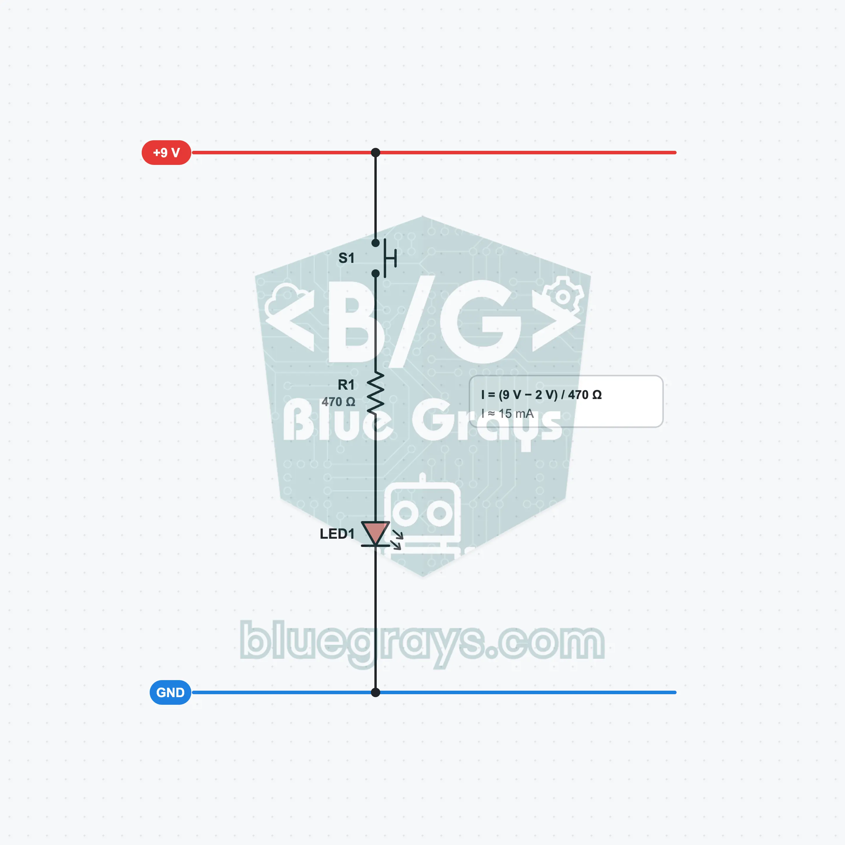
The button opens and closes the path between the + rail and the resistor. While it is pressed the LED lights with about 15 mA; when you release it the current stops and the LED goes out.
A button is a bridge
Inside the button there are two metal terminals that do not touch each other and a spring-loaded cap above them. When you press, the cap joins the two terminals; when you release, the spring pushes the cap back. So the button is a small bridge that you open and close with your finger.
Open circuit
While the button is not pressed, the path coming from the + rail ends at the button. Because there is no unbroken path for current to flow, no current passes through R1 and LED1 at all. This state is called an open circuit; the battery is not used either.
Closed circuit
When you press the button the path is completed: the + rail, S1, R1, LED1 and GND. The current is (9 V − 2 V) / 470 Ω ≈ 15 mA, as in the first circuit. Because the button is a good conductor, no voltage drops across it and the brightness does not change.
Diagonal legs
The top and bottom legs of the button in the same row are connected inside. If you use the top left and bottom right legs, the button works correctly whichever way around it is fitted. That is why the + jumper wire goes into the top half of row 6 and R1 into the bottom half of row 8.
Truth Table
| S1 | Circuit | LED1 |
|---|---|---|
| Released | Open | Off |
| Pressed | Closed | On |
The button completes the path only for as long as it is held down.
Formulas
LED current (S1 pressed)
I = (Vbat − VLED) / R1
Example: (9 V − 2 V) / 470 Ω ≈ 15 mA
LED current (S1 released)
I = 0
Example: Because the path is open, no current flows; the battery is not used
Common Mistakes
The LED does not light when you press the button.
The bridge jumper that joins the top and bottom GND rails is missing, or the LED is fitted backwards.
The LED lights without the button being pressed.
The + jumper wire and R1 are plugged into the row with the same number. The jumper wire must be in the top half of row 6, R1 in the bottom half of row 8.
The LED does not react at all, and the connections are correct.
The button is not fully seated. Place it upright over the gap and push it all the way down.
FAQ
Why does the button have four legs?
There are actually only two terminals inside; each terminal comes out as one leg on each of the two sides of the body. Four legs make the button sit firmly on a board. On the breadboard, the legs that fall in the same row on the two sides of the gap are connected to each other; when you press the button, the two rows are joined.
Can I put the button after the LED, on the GND side?
Yes. The button, the resistor and the LED are in series; in a series circuit the order does not matter. Wherever it is on the path, no current can flow while the button is open, and the same 15 mA flows while it is closed. The only rule that does not change is the direction of the LED: the anode must always face the + side.
How do I keep the LED on after I release the button?
A push button is momentary; the spring inside opens the contact as soon as you lift your finger. To keep the LED on, you need either a slide switch that holds its position or a memory circuit that remembers the state. You will build both in later circuits of the series.
Does the circuit use the battery while the button is not pressed?
No. While the button is open the path is broken and no current flows at all, so the battery does not drain. Current flows only for as long as you press the button. This circuit can wait for days with the battery connected; still, taking the battery off the clip when you are done is a good habit.