
E12 Resistor Values: E6, E12, E24 and E96 Series Tables
E12 resistor values explained: E6, E12, E24 and E96 series, their link to tolerance, a full E12/E24 table, picking the nearest value and series-parallel tricks.

E12 resistor values, and the other standard resistor values, explain why resistors are sold in odd steps such as 1 kΩ, 1.2 kΩ, 1.5 kΩ, 1.8 kΩ and 2.2 kΩ: manufacturers don't make every value, only the ones on standard lists called the E series. The most common is the E12 series, with 12 values per decade; precision circuits use E24, E48 and E96. In this guide we explain the logic behind the series, how they relate to tolerance and how to pick the resistor closest to the value you calculated.
When your maths gives you 162 Ω for an LED or 3.4 kΩ for a voltage divider, you probably won't find that exact value in your drawer. That isn't a gap in the range but a deliberate design: these series, set in the 1950s and defined today in the IEC 60063 standard, were built to cover the whole range with as few values as possible. Below you'll find the full E12 and E24 table, how to make in-between values in series or parallel, the values that come in Arduino kits and an Arduino sketch that finds the nearest value; for a quick answer you can also use the Standard Resistor Value tool.
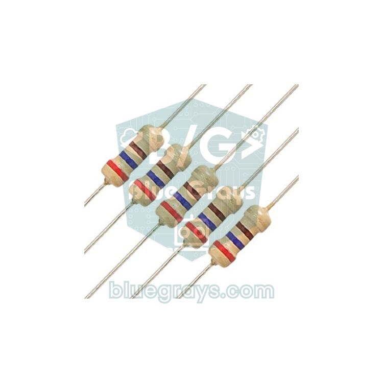
What are the E series? Why 1.0, 1.2, 1.5, 1.8?
The E series split the range from 1 to 10 into steps of equal ratio. E12 has 12 steps, and each value is about 1.21 times the previous one, because the 12th root of 10 is 1.2115. So 1.0 × 1.21 ≈ 1.2, 1.2 × 1.21 ≈ 1.5, 1.5 × 1.21 ≈ 1.8, and so on. The reason for equal ratios rather than equal differences is simple: a 10 Ω gap between 100 Ω and 110 Ω matters, while the same 10 Ω between 100 kΩ and 100.01 kΩ means nothing. What counts is the percentage difference, and a geometric sequence gives the same percentage step in every decade.
The number in a series' name is the count of values per decade: E6 has 6, E12 has 12, E24 has 24 and E96 has 96. The values repeat in every decade, so the 4.7 in E12 is made as 4.7 Ω, 47 Ω, 470 Ω, 4.7 kΩ, 47 kΩ, 470 kΩ and 4.7 MΩ. As a formula, the n-th value of a series with N values is 10^(n/N). In E24, 2.7, 3.0, 3.3, 3.6, 3.9, 4.3 and 4.7 drift slightly from that formula, which gives 2.61, 2.87, 3.16, 3.48, 3.83, 4.22 and 4.64 at those steps. The drift is historical: newer series were built to keep the older values, which is why 3.3 and 4.7 survive in every list. E48 and above follow the formula almost exactly to three digits.
E series and tolerance
It's no coincidence that each series is paired with a tolerance class. In E12 two neighbouring values are about 1.21 apart; with ±10% resistors, the upper limit of 1.0 is 1.1 and the lower limit of 1.2 is 1.08. The tolerance bands touch, so every number between 1 and 10 falls inside the band of at least one resistor. Making more values for ±10% parts would be pointless; as tolerance gets tighter, the series gets denser.
| Series | Values per decade | Step ratio | Typical tolerance | Where it's used |
|---|---|---|---|---|
| E3 | 3 | ≈ 2.15 | Wider than ±20% | Old and coarse; today mostly capacitors |
| E6 | 6 | ≈ 1.47 | ±20% | Capacitors, inductors, old resistors |
| E12 | 12 | ≈ 1.21 | ±10% | General-purpose resistors, starter kits |
| E24 | 24 | ≈ 1.10 | ±5% (often ±1% today) | Carbon and metal film resistors |
| E48 | 48 | ≈ 1.05 | ±2% | Precision analog circuits |
| E96 | 96 | ≈ 1.024 | ±1% | Metal film and SMD resistors |
| E192 | 192 | ≈ 1.012 | ±0.5% and tighter | Test equipment, reference circuits |
Full table: E6, E12 and E24 values
The table below lists the 24 values of E24 and shows whether each one also appears in E12 and E6. Multiply a value by 10, 100, 1000 and so on to find it in each decade; the last column shows the versions you'll meet most often.
| E24 | In E12 | In E6 | Common values |
|---|---|---|---|
| 1.0 | Yes | Yes | 10 Ω, 100 Ω, 1 kΩ, 10 kΩ, 100 kΩ |
| 1.1 | No | No | 110 Ω, 1.1 kΩ, 11 kΩ |
| 1.2 | Yes | No | 120 Ω, 1.2 kΩ, 12 kΩ |
| 1.3 | No | No | 130 Ω, 1.3 kΩ, 13 kΩ |
| 1.5 | Yes | Yes | 150 Ω, 1.5 kΩ, 15 kΩ |
| 1.6 | No | No | 160 Ω, 1.6 kΩ, 16 kΩ |
| 1.8 | Yes | No | 180 Ω, 1.8 kΩ, 18 kΩ |
| 2.0 | No | No | 200 Ω, 2 kΩ, 20 kΩ |
| 2.2 | Yes | Yes | 22 Ω, 220 Ω, 2.2 kΩ, 22 kΩ |
| 2.4 | No | No | 240 Ω, 2.4 kΩ, 24 kΩ |
| 2.7 | Yes | No | 270 Ω, 2.7 kΩ, 27 kΩ |
| 3.0 | No | No | 300 Ω, 3 kΩ, 30 kΩ |
| 3.3 | Yes | Yes | 33 Ω, 330 Ω, 3.3 kΩ, 33 kΩ |
| 3.6 | No | No | 360 Ω, 3.6 kΩ, 36 kΩ |
| 3.9 | Yes | No | 390 Ω, 3.9 kΩ, 39 kΩ |
| 4.3 | No | No | 430 Ω, 4.3 kΩ, 43 kΩ |
| 4.7 | Yes | Yes | 47 Ω, 470 Ω, 4.7 kΩ, 47 kΩ |
| 5.1 | No | No | 510 Ω, 5.1 kΩ, 51 kΩ |
| 5.6 | Yes | No | 560 Ω, 5.6 kΩ, 56 kΩ |
| 6.2 | No | No | 620 Ω, 6.2 kΩ, 62 kΩ |
| 6.8 | Yes | Yes | 68 Ω, 680 Ω, 6.8 kΩ, 68 kΩ |
| 7.5 | No | No | 750 Ω, 7.5 kΩ, 75 kΩ |
| 8.2 | Yes | No | 820 Ω, 8.2 kΩ, 82 kΩ |
| 9.1 | No | No | 910 Ω, 9.1 kΩ, 91 kΩ |
The E96 table has 96 rows, so it won't fit here, but its start is worth knowing: 1.00, 1.02, 1.05, 1.07, 1.10, 1.13, 1.15, 1.18, 1.21, 1.24 and so on. The three-character EIA-96 codes on SMD resistors, such as 01C, follow the order of this list directly: 01 is the first value of the series, 100, and the letter C is the ×100 multiplier, so 01C = 10 kΩ. The details are in SMD Resistor Codes.
Picking the resistor closest to your calculated value
The value you get from Ohm's law or any other formula almost never lands on a standard value. When you choose, ask two questions: what happens if the value is a little high or low, and how sensitive is the circuit? The general rules are:
- For current-limiting resistors, go one value up. Turn the 162 Ω you calculated for an LED, a transistor base or a buzzer into 180 Ω; the current drops a little, but nothing is overstressed. For LED resistors, the LED resistor calculator rounds straight to a standard value.
- For pull-up and pull-down resistors, the nearest value is fine. Using 8.2 kΩ or 12 kΩ instead of 10 kΩ makes no difference in most circuits.
- For voltage dividers, keep the ratio. Rather than rounding the two resistors separately, pick the pair that best preserves the ratio; there's an example below.
- In timing and filter circuits (555, RC filters) the error goes straight into the frequency; use E24 or E96, or combine two resistors.
- Work out the percentage error: (chosen − calculated) / calculated × 100. If the result is smaller than the resistor's tolerance, your choice is good.
Here's an example. You want to bring a 5 V signal down to 3.3 V for an ESP32 pin. The divider formula is Vout = Vin × R2 / (R1 + R2), so R2 has to be 3.3 / 5 = 0.66 of the total. With the E24 series, 10 kΩ (R1) and 20 kΩ (R2) give 3.33 V, almost perfect. If you only have E12, 1.2 kΩ and 2.2 kΩ give 3.24 V, while 1 kΩ and 2.2 kΩ give 3.44 V, still safe but closer to the limit. You can try these numbers in seconds with the voltage divider tool.
Making in-between values in series and parallel
If you need a value that isn't in your kit, you can combine two standard resistors. In series the resistances add up (R = R1 + R2); in parallel the result is smaller than the smaller one (R = R1 × R2 / (R1 + R2)), and two equal resistors in parallel give half the value. The formulas and worked examples are in Series and Parallel Resistor Calculation, and the series-parallel tool handles quick sums. Some in-between values you can make with E12 parts only:
| Needed | E12 solution | Result | Error |
|---|---|---|---|
| 2 kΩ | 1 kΩ + 1 kΩ (series) | 2 kΩ | 0% |
| 3 kΩ | 1.5 kΩ + 1.5 kΩ (series) | 3 kΩ | 0% |
| 5 kΩ | 10 kΩ ∥ 10 kΩ (parallel) | 5 kΩ | 0% |
| 6.5 kΩ | 4.7 kΩ + 1.8 kΩ (series) | 6.5 kΩ | 0% |
| 75 Ω | 150 Ω ∥ 150 Ω (parallel) | 75 Ω | 0% |
| 162 Ω | 150 Ω + 12 Ω (series) | 162 Ω | 0% |
| 1.25 kΩ | 1.2 kΩ + 47 Ω (series) | 1.247 kΩ | −0.24% |
Common resistor values in Arduino kits
The 600-piece resistor boxes in starter kits usually hold 30 values between 10 Ω and 1 MΩ, a mix of E12 and E24. Knowing what each one is for helps you recognise a value on a schematic at a glance:
| Value | Series | Typical use with Arduino |
|---|---|---|
| 220 Ω | E12 | LED current limiting at 5 V (about 14 mA with a red LED) |
| 330 Ω | E12 | Dimmer LEDs, LEDs on 3.3 V boards |
| 1 kΩ | E12 | Transistor base, protecting a signal line |
| 2 kΩ | E24 | Voltage divider for the HC-SR04 ECHO line (with 1 kΩ) |
| 4.7 kΩ | E12 | I2C pull-ups, pull-up for the DS18B20 and DHT data lines |
| 10 kΩ | E12 | Button pull-down, LDR and NTC dividers |
| 100 kΩ | E12 | Low-current dividers for measuring battery voltage |
| 1 MΩ | E12 | Piezo knock sensor, capacitive touch |
Don't be surprised to find values such as 5.1 kΩ, 51 Ω or 200 Ω in your kit; they're E24 values used in specific places, like the CC resistors on USB-C connectors (5.1 kΩ). To read a resistor's value from its bands, see Resistor Colour Codes or the resistor colour code tool: four-band resistors usually come in E24 values, and five-band ±1% resistors often in E96 values.
Finding the nearest standard value with Arduino
The sketch below takes a resistance you type into the Serial Monitor and prints the nearest E12 and E24 values, the next E12 value up for current limiting, and the percentage error of each. Type 3500 and press Enter, for example, and you'll see 3.3 kΩ (−5.7%) for E12, 3.6 kΩ (+2.9%) for E24 and 3.9 kΩ (+11.4%) as the next value up. The algorithm is simple: it finds the decade with log10(), compares the value with every entry in the series and keeps the closest one.
1// Standart direnç bulucu (E12 + E24) / standard resistor finder (E12 + E24)
2const float E12[] = {1.0, 1.2, 1.5, 1.8, 2.2, 2.7, 3.3, 3.9, 4.7, 5.6, 6.8, 8.2};
3const float E24[] = {1.0, 1.1, 1.2, 1.3, 1.5, 1.6, 1.8, 2.0, 2.2, 2.4, 2.7, 3.0,
4                     3.3, 3.6, 3.9, 4.3, 4.7, 5.1, 5.6, 6.2, 6.8, 7.5, 8.2, 9.1};
5
6// Seriden en yakın değeri döndürür / returns the nearest value in a series
7float nearestValue(float ohms, const float *series, int count) {
8  float decade = pow(10, floor(log10(ohms)));    // 3500 → 1000
9  float best = series[0] * decade;
10  for (int k = 0; k <= count; k++) {
11    // k == count: bir üst on katın 1,0'ı (9,6k → 10k) / next decade's 1.0 (9.6k → 10k)
12    float candidate = (k < count ? series[k] : 10.0) * decade;
13    if (fabs(candidate - ohms) < fabs(best - ohms)) best = candidate;
14  }
15  return best;
16}
17
18// Hedefe eşit ya da büyük ilk değer (LED dirençleri için) / first value at or above the target (for LED resistors)
19float nextUpValue(float ohms, const float *series, int count) {
20  float decade = pow(10, floor(log10(ohms)));
21  for (int k = 0; k < count; k++) {
22    if (series[k] * decade >= ohms * 0.999) return series[k] * decade;   // küçük float payı / small float margin
23  }
24  return 10.0 * decade;                          // bir üst on kat / next decade
25}
26
27void printResult(const char *name, float target, float value) {
28  float error = (value - target) / target * 100.0;   // yüzde hata / percent error
29  Serial.print(name);
30  Serial.print(F(": "));
31  Serial.print(value, 1);
32  Serial.print(F(" ohm  (hata / error "));
33  Serial.print(error, 1);
34  Serial.println(F(" %)"));
35}
36
37void setup() {
38  Serial.begin(9600);
39  Serial.println(F("Direnc degerini ohm olarak yaz / Type a resistance in ohms:"));
40}
41
42void loop() {
43  if (Serial.available() == 0) return;
44  float target = Serial.parseFloat();            // ör. 3500 / e.g. 3500
45  while (Serial.available()) Serial.read();      // satır sonunu temizle / clear the line ending
46  if (target <= 0) return;
47  printResult("E12", target, nearestValue(target, E12, 12));
48  printResult("E24", target, nearestValue(target, E24, 24));
49  printResult("E12 ust / up", target, nextUpValue(target, E12, 12));
50}
The sketch uses float on the Arduino Uno, which gives 6–7 significant digits, far more than enough for choosing resistors. It works with any line-ending setting in the Serial Monitor, because leftover characters in the buffer are cleared after each reading. Add the E96 values to an array and the same functions work for the precision series too; just pass 96 as the array length.
Common mistakes
- Assuming every value exists: round numbers such as 250 Ω or 4 kΩ aren't in E12 or E24; choose between 240 Ω and 270 Ω, or between 3.9 kΩ and 4.3 kΩ.
- Rounding an LED resistor down: turning a calculated 162 Ω into 150 Ω raises the current; always go one value up for current-limiting resistors.
- Forgetting tolerance: a ±5% 10 kΩ resistor can be anywhere between 9.5 kΩ and 10.5 kΩ; for precise measurements, check it with a multimeter.
- Rounding both divider resistors separately: the ratio shifts; recalculate the output voltage with the values you picked.
- Ignoring the power rating: a standard value is only the resistance; a 1/4 W resistor can dissipate at most 0.25 W. Check with P = I² × R.
- Mixing up 4k7 and 4R7: on a schematic, 4k7 means 4.7 kΩ and 4R7 means 4.7 Ω. The letter marks where the decimal point goes.
Once you understand standard resistor values, you'll see why 4.7 kΩ, 220 Ω and 10 kΩ turn up on schematics everywhere. To strengthen the basics, Ohm's Law is a good next step. In the BlueGrays app you can see step by step, with circuit diagrams and code, which resistor was chosen and why in projects such as the LED, the traffic light, the button and the LDR.
Frequently asked questions
What are the E12 resistor values?
The E12 series has 12 values per decade: 1.0, 1.2, 1.5, 1.8, 2.2, 2.7, 3.3, 3.9, 4.7, 5.6, 6.8 and 8.2. Multiplying them by 10, 100, 1000 and so on gives values such as 12 Ω, 120 Ω, 1.2 kΩ and 12 kΩ.
Why can't I find a 5 kΩ resistor?
5 kΩ isn't in the E12 or E24 series; the nearest values are 4.7 kΩ and 5.1 kΩ (5.1 kΩ only in E24). If you need exactly 5 kΩ, put two 10 kΩ resistors in parallel or use 4.99 kΩ from the E96 series.
What's the difference between E12 and E24?
E12 has 12 values per decade and E24 has 24; E24 contains every E12 value and adds 12 more in between, such as 1.1, 1.3, 1.6 and 2.0. Historically E12 was defined for ±10% resistors and E24 for ±5% ones.
What should I do if my calculated resistor value isn't standard?
For current-limiting resistors such as an LED or a transistor base, take the next standard value up; otherwise take the nearest value. If the error is too large, combine two resistors in series or parallel to get closer to the exact value.
What are the most common resistor values?
In Arduino and hobby electronics the most common are 220 Ω, 330 Ω, 1 kΩ, 4.7 kΩ, 10 kΩ and 100 kΩ. They cover most basic jobs: LED current limiting, driving transistors, I2C pull-ups, button pull-downs and voltage dividers.
When is the E96 series used?
E96 was defined for ±1% precision resistors and is common in measurement circuits, precise voltage dividers and SMD resistors. The EIA-96 codes printed on SMD resistors, such as 01C, are simply the position of the value in the E96 list plus a multiplier letter.
Projects to build after reading this
See all projects
LED Blink
The very first hello of electronics: switching a single LED on and off. The Arduino turns the LED on and off at short intervals, so the light blinks quickly.

Two LEDs Blinking Alternately
Two LEDs blink quickly in turn: when one lights up the other goes off, as if they were tossing a ball back and forth.

Traffic Light
A tiny copy of the traffic light you see on the road every day. Red stays on for two seconds, yellow flashes for a moment, green stays on for two seconds, then it goes back to red through yellow…

LED Control with a Push Button (Push)
Just like a doorbell: the light stays on as long as you press, and goes off when you let go.

Measuring Light Intensity with an LDR
Want to see how bright your room is as a number? The LDR, a small part that reacts to light, measures the light around it, and the Arduino writes the value to your computer screen every half second.

Night Light with Ldr
A little night light that turns on by itself when it gets dark and goes off when morning comes.

LED Blink with ESP32
Teaches basic GPIO output usage with ESP32. We achieve a blinking effect by turning an LED on and off from a digital pin. ESP32 version of the classic blink project on Arduino UNO; the basic blink commands in the Arduino environment are the same, but the ESP32's pin layout and 3.3 V GPIO levels differ from those of the Arduino UNO.
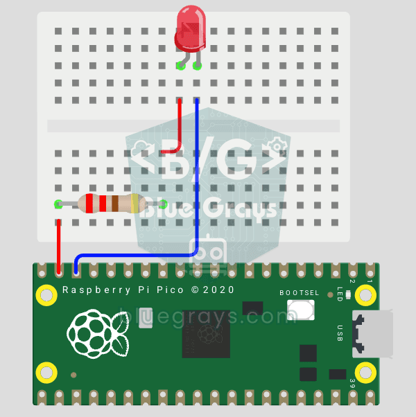
Raspberry Pi Pico: Controlling an External LED (Breadboard)
The next step after the Pico's built-in LED: connect an external LED on a breadboard and control it through pin GP14. You'll learn how to use any of the Pico's GPIO pins as an output, the LED's polarity (long leg = anode/+, short leg = cathode/–) and why a current-limiting resistor (220Ω) is a must. Without the resistor, too much current flows through the LED and it can burn out.