
Resistor Color Code: How to Read 4, 5 and 6 Band Resistors
How do you read resistor color codes? Color chart for 4, 5 and 6 band resistors, worked examples, and the colors of 220 Ω, 1 kΩ and 10 kΩ resistors.

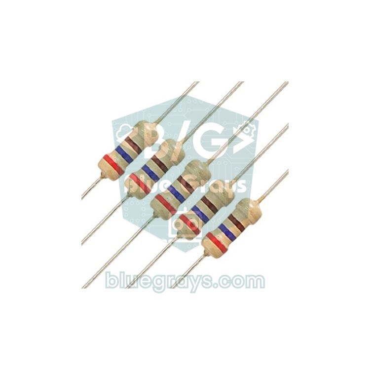
The resistor color code is an international system of colored rings printed on a resistor's body that shows its value, its tolerance and sometimes its temperature coefficient. To find out how many ohms a resistor is, you convert the first two or three bands from left to right into digits, then multiply by the multiplier band that follows; the gold or silver band on the far right tells you how far the real value may deviate. For example, a resistor with red-red-brown-gold bands means 22 × 10 = 220 Ω ±5%.
Printing digits on a tiny resistor is difficult and they can be wiped off by soldering heat, whereas colored bands can be read however the body is turned. In this post you'll learn to read 4, 5 and 6 band resistors step by step, work out which end to start from, recognize the 220 Ω, 1 kΩ and 10 kΩ resistors from Arduino kits at a glance, verify your reading with a multimeter and build a simple ohmmeter with Arduino. For a quick check you can also use the resistor color code calculator.
What is the resistor color code and how does it work?
In the color code system every color has a digit: they run from black 0 to white 9. What changes is the job of each band depending on its position. On a 4 band resistor the first two bands are the significant digits, the third band is the multiplier and the fourth is the tolerance band. On 5 and 6 band precision resistors the number of significant digits rises to three; on 6 band resistors the last band also shows how much the resistance changes with temperature. It helps to think of the multiplier band as "how many zeros to add after the digits": red means two zeros, orange three zeros, yellow four zeros. When gold and silver are used as multipliers, they divide the value by 10 or 100, which lets values below 1 Ω be written too. Older resistors with only three bands have no tolerance band, and in that case the tolerance is taken as ±20%. Once you know the value, you can easily calculate the current in the circuit with Ohm's Law.
| Color | Digit | Multiplier | Tolerance | Temperature coefficient |
|---|---|---|---|---|
| Black | 0 | ×1 | – | 250 ppm/K |
| Brown | 1 | ×10 | ±1% | 100 ppm/K |
| Red | 2 | ×100 | ±2% | 50 ppm/K |
| Orange | 3 | ×1 k | Rare (precision) | 15 ppm/K |
| Yellow | 4 | ×10 k | Rare (precision) | 25 ppm/K |
| Green | 5 | ×100 k | ±0.5% | 20 ppm/K |
| Blue | 6 | ×1 M | ±0.25% | 10 ppm/K |
| Violet | 7 | ×10 M | ±0.1% | 5 ppm/K |
| Grey | 8 | ×100 M | Rare (precision) | 1 ppm/K |
| White | 9 | ×1 G | – | – |
| Gold | – | ×0.1 | ±5% | – |
| Silver | – | ×0.01 | ±10% | – |
| None (no band) | – | – | ±20% | – |
Which end do you read a resistor from?
- Gold or silver band on the right: These colors are almost always the tolerance band and sit on the far right. Turn the resistor so this band is on the right and start reading from the left.
- Look at the gap: The tolerance band is usually a little farther from the other bands; the end where the bands are bunched together is the starting side.
- Closeness to the end: In most makes the first band is closer to the end of the body, and the last band is closer to the middle.
- First band rule: The first band can't be gold, silver or black. If one of the ends has one of these colors, you must start reading from the other end.
- Standard value test: If the value you read doesn't fit the standard series (E12, E24), you're most likely reading the resistor backwards.
How do you read a 4 band resistor?
- Hold the resistor with the gold or silver band on the right.
- Write down the digit of the first band: brown means 1.
- Add the digit of the second band next to it: black is 0, so the number becomes 10.
- The third band is the multiplier; add as many zeros as the color's digit: orange is 3, so the number becomes 10 000.
- Simplify the result (10 000 Ω = 10 kΩ) and read the tolerance from the fourth band: gold means ±5%.
With these steps, a resistor with brown-black-orange-gold bands comes out as 10 kΩ ±5%. The tolerance says the real value may deviate by that percentage: a 10 kΩ ±5% resistor can measure anywhere between 9.5 kΩ and 10.5 kΩ, and that's completely normal. Likewise, a 220 Ω ±5% resistor is expected to measure between 209 and 231 Ω. In circuit diagrams and parts lists, values are often written in shortened form: 4K7 means 4.7 kΩ; 1M means 1 MΩ; 4R7 means 4.7 Ω. The letters K, M and R show both the unit and the position of the decimal point, so a tiny decimal point being rubbed off doesn't corrupt the value.
How do you read a 5 band resistor?
The logic on 5 band resistors is the same, only the number of significant digits rises to three: the first three bands are digits, the fourth band is the multiplier and the fifth band is the tolerance. These are usually metal film resistors with a blue or light blue body, and their tolerance is mostly ±1%, shown by a brown band; beige carbon film resistors are generally 4 band and ±5%. For example, a resistor with yellow-violet-black-brown-brown bands is 470 × 10 = 4700 Ω, i.e. 4.7 kΩ ±1%. The same value is written on a 4 band resistor as yellow-violet-red-gold: on a 5 band the multiplier is one step smaller, because the third digit already carries a zero. That's why counting the bands before you start reading is so important; if you mistake a 5 band resistor for a 4 band, you'll read the first two bands as 47 and the third as the multiplier and end up with a completely wrong result. Thanks to three significant digits, finer values such as 4.99 kΩ or 1.02 kΩ can also be written on 5 band resistors.
6 band resistors and the temperature coefficient
The first five bands of a 6 band resistor are read exactly like a 5 band one. The sixth band gives the temperature coefficient (TCR) in ppm/K; that is, how many parts per million the resistance changes for every 1 °C rise in temperature. For example, a 10 kΩ resistor with a 50 ppm/K (red) coefficient changes by 10 000 × 0.00005 = 0.5 Ω per degree; if it warms up by 30 °C, it drifts about 15 Ω, i.e. 0.15%. In hobby projects this difference is mostly insignificant, but in precision measuring instruments, reference voltage dividers and temperature-sensitive circuits, low-coefficient resistors are chosen. A resistor with brown-green-black-red-brown-red bands reads as 150 × 100 = 15 kΩ, ±1% and 50 ppm/K.
Example readings: step-by-step calculations
| Bands | Calculation | Result |
|---|---|---|
| Brown, black, brown, gold | 10 × 10 | 100 Ω ±5% |
| Red, red, brown, gold | 22 × 10 | 220 Ω ±5% |
| Orange, orange, brown, gold | 33 × 10 | 330 Ω ±5% |
| Brown, black, red, gold | 10 × 100 | 1 kΩ ±5% |
| Yellow, violet, red, gold | 47 × 100 | 4.7 kΩ ±5% |
| Brown, black, orange, gold | 10 × 1000 | 10 kΩ ±5% |
| Brown, black, yellow, silver | 10 × 10 000 | 100 kΩ ±10% |
| Brown, black, green, gold | 10 × 100 000 | 1 MΩ ±5% |
| Yellow, violet, gold, gold | 47 × 0.1 | 4.7 Ω ±5% |
| Red, red, black, black, brown | 220 × 1 | 220 Ω ±1% |
| Orange, white, black, brown, brown | 390 × 10 | 3.9 kΩ ±1% |
| Brown, green, black, red, brown, red | 150 × 100 | 15 kΩ ±1%, 50 ppm/K |
Common resistors in Arduino kits
| Value | 4 band (±5%) | 5 band (±1%) | Typical use |
|---|---|---|---|
| 220 Ω | Red, red, brown, gold | Red, red, black, black, brown | Limiting LED current at 5 V |
| 330 Ω | Orange, orange, brown, gold | Orange, orange, black, black, brown | LED, slightly lower brightness |
| 1 kΩ | Brown, black, red, gold | Brown, black, black, brown, brown | Transistor base, indicator LEDs |
| 4.7 kΩ | Yellow, violet, red, gold | Yellow, violet, black, brown, brown | I2C pull-up, DS18B20 data line |
| 10 kΩ | Brown, black, orange, gold | Brown, black, black, red, brown | Button pull-up/pull-down, LDR divider |
| 100 kΩ | Brown, black, yellow, gold | Brown, black, black, orange, brown | High-value divider for measuring battery voltage |
Some values keep turning up in ready-made Arduino starter kits. 220 Ω is the standard choice for limiting the current of a red LED running on 5 V: since a red LED drops about 2 V, the current is (5 − 2) / 220 ≈ 13.6 mA, which stays safely below the LED's 20 mA limit. The same LED draws about 9 mA with 330 Ω and glows a little dimmer. 1 kΩ is used to drive transistor bases and low-current indicator LEDs. 10 kΩ is the most used resistor in kits, as the pull-up and pull-down resistor for buttons and as the second half of voltage dividers built with LDRs and thermistors. For the details of the current calculation, see LED resistor calculation, and to understand their role with buttons, see pull-up and pull-down resistors.
Standard resistor values: the E12 and E24 series
Resistors aren't made in every value; they're produced in standard series chosen so that the tolerance ranges overlap. The E24 series used for ±5% resistors contains 24 values per decade: 10, 11, 12, 13, 15, 16, 18, 20, 22, 24, 27, 30, 33, 36, 39, 43, 47, 51, 56, 62, 68, 75, 82 and 91. The ±10% E12 series takes only 10, 12, 15, 18, 22, 27, 33, 39, 47, 56, 68 and 82 of these; ±1% metal film resistors are in the 96-value E96 series. This is very useful for checking your reading: if you read a 4 band resistor and get a start like 25 or 85, you've most likely misjudged a color or turned the resistor around. To find the standard resistor closest to the value you calculated, use the standard resistor value tool, and to combine several resistors into a custom value, see series and parallel resistor calculation.
Measuring and verifying a resistor with a multimeter
- Remove the resistor from the circuit or desolder at least one leg; other components in the circuit create parallel paths and give a wrong value.
- Plug the black probe into COM and the red probe into the VΩ jack and turn the dial to the Ω range.
- On a manual-range multimeter pick the range just above the expected value: for 220 Ω the 2k range is suitable, for 10 kΩ the 20k range.
- Touch the probes to the two legs of the resistor; a resistor has no polarity, so swapping the probes doesn't change the result.
- If you see "1" or "OL" on the display, the value is larger than the range you picked; go up one range.
- Check whether the reading is within the tolerance range: a 220 Ω ±5% resistor should read between 209 and 231 Ω. For values under 10 Ω, subtract the probes' own resistance (about 0.2–0.5 Ω), which you can measure by touching the probes together.
Building a simple ohmmeter with Arduino
If you don't have a multimeter, or you want to practice with Arduino, you can measure an unknown resistor with a voltage divider made of two resistors. Connect a known 10 kΩ resistor between the supply and an analog pin, and the resistor you want to measure (Rx) between the analog pin and GND. This method doesn't give laboratory accuracy, but it's great for telling whether a resistor is 1 kΩ or 10 kΩ and for grasping the logic of analog-to-digital conversion.
| Connection | Arduino Uno | ESP32 | Raspberry Pi Pico |
|---|---|---|---|
| Top end of the known resistor (10 kΩ) | 5V | 3V3 | 3V3 (pin 36) |
| Measurement point (junction of the two resistors) | A0 | GPIO 34 | GP26 (ADC0) |
| Bottom end of the resistor to measure (Rx) | GND | GND | GND |
1// Basit ohmmetre / Simple ohmmeter
2// 5V -> R_BILINEN (10 kOhm) -> A0 -> Rx -> GND
3const int OLCUM_PIN = A0;          // ölçüm noktası / measurement node
4const float R_BILINEN = 10000.0;   // bilinen direnç (ohm), multimetreyle ölçülen değer / known resistor (ohm), measured value
5
6void setup() {
7  Serial.begin(9600);
8}
9
10void loop() {
11  long toplam = 0;
12  for (int i = 0; i < 16; i++) {   // 16 ölçümün ortalaması / average of 16 readings
13    toplam += analogRead(OLCUM_PIN);
14    delay(2);
15  }
16  float ortalama = toplam / 16.0;
17
18  if (ortalama > 1015.0) {         // A0 neredeyse 5V: direnç yok / A0 almost 5V: no resistor
19    Serial.println(F("Direnc takili degil / No resistor"));
20  } else {
21    float rx = R_BILINEN * ortalama / (1023.0 - ortalama);   // gerilim bölücü formülü / voltage divider formula
22    Serial.print(F("Rx = "));
23    if (rx >= 1000.0) {
24      Serial.print(rx / 1000.0, 2);
25      Serial.println(F(" kohm"));
26    } else {
27      Serial.print(rx, 1);
28      Serial.println(F(" ohm"));
29    }
30  }
31  delay(1000);
32}
The circuit is a voltage divider: the voltage at A0 is Vcc × Rx / (R_BILINEN + Rx). Because analogRead uses the same 5 V as its reference, the supply voltage cancels out of the formula and you're left with Rx = R_BILINEN × reading / (1023 − reading). For example, with Rx = 10 kΩ the reading comes out at about 511. Averaging 16 readings reduces noise. You get the most accurate result when Rx is close to the known resistor; with a 10 kΩ reference, 1 kΩ–100 kΩ is measured with an error of a few percent, but at extreme values such as 100 Ω or 1 MΩ even a single ADC step causes a large error. The known resistor's own tolerance also feeds straight into the result, so enter the real value you measured with a multimeter for R_BILINEN, not the label value. You can see the result by opening the Serial Monitor at 9600 baud.
Measuring with the ESP32 and Raspberry Pi Pico
On the ESP32 it's enough to build the same circuit with a 3V3 supply, set the pin to 34 in the code and use 4095 instead of 1023, because the ESP32's ADC is 12-bit and returns values in the 0–4095 range. However, the ESP32 ADC is nonlinear especially near 0 V and 3.3 V, so the measurement can deviate by a few percent more. Take the measurement on ADC1 pins (GPIO 32–39), because ADC2 pins can't be used while Wi-Fi is on. On the Raspberry Pi Pico, with MicroPython you can combine both a solver that calculates the value from a color sequence and an ohmmeter that measures on GP26 in a single program:
1from machine import ADC
2import time
3
4# Renk -> rakam / Color -> digit
5RAKAM = {"siyah": 0, "kahverengi": 1, "kirmizi": 2, "turuncu": 3, "sari": 4,
6         "yesil": 5, "mavi": 6, "mor": 7, "gri": 8, "beyaz": 9}
7# Carpan = 10 uzeri rakam / Multiplier = 10 to the power of digit
8CARPAN = {renk: 10 ** r for renk, r in RAKAM.items()}
9CARPAN["altin"] = 0.1
10CARPAN["gumus"] = 0.01
11# Tolerans (%) / Tolerance (%)
12TOLERANS = {"kahverengi": 1, "kirmizi": 2, "yesil": 0.5, "mavi": 0.25,
13            "mor": 0.1, "altin": 5, "gumus": 10}
14
15def renkten_deger(bantlar):
16    # 4 bant: 2 rakam, 5-6 bant: 3 rakam / 4 bands: 2 digits, 5-6 bands: 3 digits
17    if len(bantlar) == 4:
18        adet = 2
19    elif len(bantlar) in (5, 6):
20        adet = 3
21    else:
22        raise ValueError("4, 5 ya da 6 bant / 4, 5 or 6 bands")
23    sayi = 0
24    for renk in bantlar[:adet]:
25        sayi = sayi * 10 + RAKAM[renk]
26    deger = sayi * CARPAN[bantlar[adet]]
27    tolerans = TOLERANS.get(bantlar[adet + 1])
28    return deger, tolerans
29
30def bicimle(ohm):
31    ohm = float(ohm)
32    if ohm >= 1e6:
33        return "{:.2f} MOhm".format(ohm / 1e6)
34    if ohm >= 1e3:
35        return "{:.2f} kOhm".format(ohm / 1e3)
36    return "{:.1f} Ohm".format(ohm)
37
38adc = ADC(26)            # GP26 = ADC0
39R_BILINEN = 10000        # multimetreyle olculen deger / value measured with a multimeter
40
41def olc():
42    toplam = 0
43    for _ in range(16):  # 16 olcumun ortalamasi / average of 16 readings
44        toplam += adc.read_u16()
45        time.sleep_ms(2)
46    ham = toplam / 16
47    if ham > 65000:      # direnc yok / no resistor
48        return None
49    return R_BILINEN * ham / (65535 - ham)
50
51deger, tol = renkten_deger(["kahverengi", "siyah", "turuncu", "altin"])
52print("Renk kodu / Color code:", bicimle(deger), "+/-", tol, "%")
53
54while True:
55    rx = olc()
56    if rx is None:
57        print("Direnc yok / No resistor")
58    else:
59        print("Olculen / Measured:", bicimle(rx))
60    time.sleep(1)
The renkten_deger() function determines how many significant digits there are by looking at the length of the band list, combines the digits, multiplies by the multiplier and returns the tolerance. olc() reads the voltage on GP26 16 times and averages it; since read_u16() gives the Pico's 12-bit measurement scaled to the 0–65535 range, 65535 is used in the formula. This way you see the value you read from the colors and the value you measured side by side in the Thonny console and can check whether the difference stays within the tolerance. If you're new to MicroPython, MicroPython basics is a good place to start.
Common mistakes and how to fix them
| Mistake | Why it happens | Fix |
|---|---|---|
| Reading from the wrong end | The tolerance band wasn't noticed, or there's brown at both ends | Put the gold/silver band on the right; if the result doesn't fit E12/E24, flip it, and if you're unsure, measure |
| Confusing red, orange and brown | Yellowish room light and thin bands make colors look alike | Look in daylight or under a white LED, with a magnifier if needed |
| Counting the bands wrong | A 5 band resistor was read as a 4 band | Count the bands first; blue-bodied resistors usually have 5 bands |
| Measuring in the circuit | Parallel components lower the measured value | Remove the resistor or lift at least one leg out of the circuit |
| Touching both ends with your fingers | Body resistance gets in parallel with the resistor | Plug the resistor into a breadboard or hold it with one hand |
| Trying to read a burnt resistor | Overheating darkens the band colors | Measure the value, find the cause of the excess current and pick a higher-wattage resistor with P = I² × R |
| Seeing "1" or "OL" on the multimeter | The range is lower than the value, or the resistor is broken | Go up one range; if it's still the same, the resistor may have gone open circuit |
After a few days of practice with color codes you'll recognize 220 Ω, 1 kΩ and 10 kΩ resistors at a glance, and when you're in doubt, the multimeter always has the final say. To put what you've learned into practice, check out the LED blinking, traffic light, button-controlled LED and LDR night light projects in the BlueGrays app; each has a circuit diagram showing which resistor goes where and ready-made code explained step by step.
Frequently asked questions
Which end do you read a resistor color code from?
Hold the resistor with the gold or silver band on the right and read from the left. The tolerance band is usually a little farther from the others, while the first band is closer to the end of the body. If you're still not sure, read it in both directions; the result that fits standard values (E12, E24) is most likely correct, and for a definite answer, measure it with a multimeter.
What are the colors of a 220 ohm resistor?
A 4 band 220 Ω resistor is red, red, brown and gold: 22 × 10 = 220 Ω, ±5%. The 5 band ±1% version reads red, red, black, black, brown. This resistor is the most common choice for driving an LED from 5 V with Arduino.
What color is a 10k resistor?
A 4 band 10 kΩ resistor has brown, black, orange and gold bands; the three zeros shown by the orange band are added to the number 10. The 5 band version reads brown, black, black, red, brown. It's used often as a button pull-up/pull-down resistor and in sensor voltage dividers with Arduino.
How many ohms is a brown black red resistor?
Brown (1), black (0) and the red multiplier (×100) together make 10 × 100 = 1000 Ω, i.e. 1 kΩ. If the fourth band is gold, the tolerance is ±5% and the resistor can measure between 950 and 1050 Ω. If the same colors are the first three bands of a 5 band resistor, the result is different, so count the bands first.
What is the difference between a 4 band and a 5 band resistor?
A 4 band resistor has two significant digits and a 5 band resistor has three; the remaining bands show the multiplier and tolerance. 5 band resistors are usually metal film resistors with ±1% tolerance and can be written with finer values such as 4.99 kΩ. In most Arduino projects, both do the same job.
Can you tell a resistor's wattage from its color code?
No, the color code gives only the value, the tolerance and, on 6 band resistors, the temperature coefficient. The power rating is judged from the body size: resistors about 6 mm long in Arduino kits are generally 1/4 W. You should calculate the power dissipated in the circuit with P = I² × R and make sure it stays below the resistor's power rating.
Projects to build after reading this
See all projects
LED Blink
The very first hello of electronics: switching a single LED on and off. The Arduino turns the LED on and off at short intervals, so the light blinks quickly. You see in the simplest way how the board

Two LEDs Blinking Alternately
Two LEDs blink quickly in turn: when one lights up the other goes off, as if they were tossing a ball back and forth. The Arduino keeps each light on for a fifth of a second and then hands over to the

Traffic Light
A tiny copy of the traffic light you see on the road every day. Red stays on for two seconds, yellow flashes for a moment, green stays on for two seconds, then it goes back to red through yellow again

LED Control with a Push Button (Push)
Just like a doorbell: the light stays on as long as you press, and goes off when you let go. The Arduino keeps listening to the button; while it's pressed the LED is on, and the moment you lift your f

Measuring Light Intensity with an LDR
Want to see how bright your room is as a number? The LDR, a small part that reacts to light, measures the light around it, and the Arduino writes the value to your computer screen every half second. C

Night Light with Ldr
A little night light that turns on by itself when it gets dark and goes off when morning comes. A light sensor measures how bright the room is, and the Arduino switches the LED on when it is dark enou

LED Blink with ESP32
Teaches basic GPIO output usage with ESP32. We achieve a blinking effect by turning an LED on and off from a digital pin. ESP32 version of the classic blink project on Arduino UNO; the basic blink commands in the Arduino environment are the same, but the ESP32's pin layout and 3.3 V GPIO levels differ from those of the Arduino UNO.
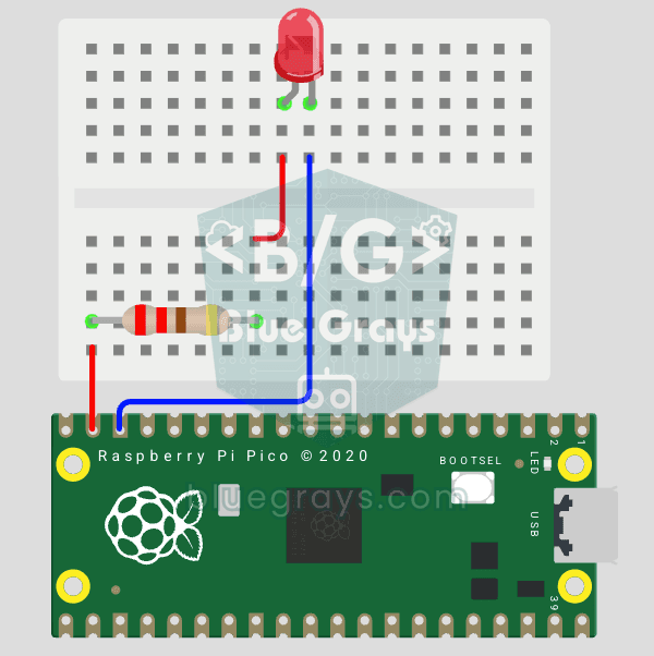
Raspberry Pi Pico: Controlling an External LED (Breadboard)
The next step after Pico’s built-in LED: connecting an external LED to the breadboard and controlling it via the GP14 pin. In this project, you’ll learn how to use any of the Pico’s general-purpose GPIO pins as an output, the LED’s polarity (long leg = anode/+, short leg = cathode/–), and why a current-limiting resistor (220Ω) is required. If you don’t include the resistor, excessive current will flow through the LED and it may burn out. The circuit is very simple: Pico GP14 → 220Ω resistor → LE