
SMD Resistor Codes: How to Read 103, 4702, 01C and 4R7
How to read SMD resistor codes: 3 and 4 digit codes, EIA-96 (01C), R as the decimal point (4R7), 0603/0805/1206 sizes, capacitor code 104 and SMD transistors.
SMD resistor codes are the short three or four character markings printed on surface-mount (SMD) resistors instead of colour bands, and they give the resistance in ohms. Once you know the rule they are very easy to read: 103 = 10 kΩ, 4702 = 47 kΩ, 4R7 = 4.7 Ω and 01C = 10 kΩ. In a three digit code the first two digits are the value and the last digit is the number of zeros to add; in a four digit code the first three digits are the value. The letter R stands in for the decimal point, and codes made of two digits and a letter are read from the EIA-96 table.
Arduino Nanos, ESP32 development boards, sensor modules and regulator boards are almost entirely made of these tiny parts. If you want to repair a module, work out which resistor feeds the LED on your board, find the value of a pull-up resistor or design your own PCB, you need to be able to read these codes. Besides resistors, this guide covers SMD capacitor codes (104 = 100 nF), size codes such as 0603, 0805 and 1206, the short markings on SMD transistors and diodes, and how to measure a part with no marking at all using an Arduino.
What is an SMD resistor, and why no colour code?
SMD (Surface Mount Device) means a part whose leads don't go through holes but are soldered straight onto pads on the surface of the circuit board. An SMD resistor is a small ceramic block with metal-plated ends; the black protective layer on top protects the resistive film and carries the code. An 0805 resistor measures only 2 × 1.25 mm, so painting four colour bands on it isn't practical; instead the value is printed as a code in white digits. Resistors of size 0402 and smaller don't even have room for that, so they are completely unmarked. Remember that the code only tells you the resistance: the power and voltage limits come from the body size, and the tolerance can usually be guessed from the type of code.
| Code type | Example | How to read it | Value | Usually found on |
|---|---|---|---|---|
| 3 digit | 103 | 10 plus 3 zeros | 10 kΩ | 5% tolerance, 0603 and larger |
| 4 digit | 4702 | 470 plus 2 zeros | 47 kΩ | 1% tolerance, 0805 and larger |
| With R | 4R7 | R = decimal point | 4.7 Ω | Values below 10 Ω |
| EIA-96 | 01C | 100 from the table × 100 | 10 kΩ | 1% tolerance 0603 resistors |
| Zero | 0, 00, 000 | Jumper | 0 Ω | Linking tracks, option settings |
How to read a 3 digit SMD resistor code
The most common format is the three digit code. The first two digits are the significant part of the value, and the third digit tells you how many zeros to add after it, in other words the power of ten. With 103 you add three zeros after 10: 10,000 Ω = 10 kΩ. In the same way 472 = 47 plus two zeros = 4,700 Ω = 4.7 kΩ; 221 = 220 Ω; 334 = 330 kΩ; and 105 = 1,000,000 Ω = 1 MΩ. These codes are normally used on ±5% resistors, and the values come from the E24 series: 10, 11, 12, 13, 15, 16, 18, 20, 22, 24, 27, 30, 33, 36, 39, 43, 47, 51, 56, 62, 68, 75, 82 and 91, plus their multiples of ten. If the value you read isn't on this list, either you're reading the code upside down or the part isn't a resistor.
| Code | Value | Common use on Arduino boards and modules |
|---|---|---|
| 100 | 10 Ω | Small series resistors, current limiting |
| 220 | 22 Ω | Series resistors on USB data lines |
| 221 | 220 Ω | LED current limiting at 5 V |
| 331 | 330 Ω | LEDs and transistor base resistors |
| 102 | 1 kΩ | On-board power and status LEDs |
| 472 | 4.7 kΩ | I2C and 1-Wire pull-up resistors |
| 103 | 10 kΩ | Reset and button pull-up resistors |
| 473 | 47 kΩ | Voltage dividers |
| 104 | 100 kΩ | Battery voltage sensing dividers |
| 105 | 1 MΩ | High-impedance inputs |
4 digit codes and the letter R: 4702, 1002, 4R7
The four digit code is used on ±1% precision resistors. The logic is the same, but the significant part has three digits: the first three digits are the value and the fourth is the number of zeros. 1002 = 100 plus two zeros = 10,000 Ω = 10 kΩ; 4702 = 47 kΩ; 1001 = 1 kΩ; 1000 = 100 Ω; 2201 = 2.2 kΩ; 1004 = 1 MΩ. Three significant digits also allow in-between E96 values such as 49.9 kΩ (4992) or 4.99 kΩ (4991). In short, the very same 10 kΩ resistor may turn up as 103, 1002 or 01C depending on the manufacturer and precision; all three are the same value.
Values below 10 Ω can't be written with a number of zeros, so the letter R takes the place of the decimal point. 4R7 = 4.7 Ω, 2R2 = 2.2 Ω, 1R0 = 1 Ω and R47 = 0.47 Ω. The four character version follows the same rule: 10R0 = 10 Ω, 4R70 = 4.7 Ω. Very small values are usually shunt resistors used for measuring current: R100 = 0.1 Ω (you'll see it on current sensing modules such as the INA219) and R010 = 0.01 Ω, or 10 mΩ. Schematics and parts lists use the same idea with the letters k and M: 4k7 = 4.7 kΩ, 2M2 = 2.2 MΩ. This notation is preferred because a decimal point that gets lost in printing could turn 4.7 kΩ into 47 kΩ.
How to read EIA-96 codes (01C, 68X, 85B)
Four digits don't fit on a 1% resistor in the 0603 size. For these, a three character system called EIA-96 is used: the first two digits (01–96) are the position number of the value in the E96 series, and the final letter is the multiplier. Value number 01 is 100, number 68 is 499 and number 85 is 750. So 01C = 100 × 100 = 10 kΩ, 68X = 499 × 0.1 = 49.9 Ω and 85B = 750 × 10 = 7.5 kΩ. You can't calculate anything from the digits here; you have to look the value up in the table. The quickest way is to type the code into the SMD code tool, which understands 3 and 4 digit codes, R notation and EIA-96.
| Letter | Multiplier | Example |
|---|---|---|
| Z | × 0.001 | 01Z = 0.1 Ω |
| Y or R | × 0.01 | 01Y = 1 Ω |
| X or S | × 0.1 | 68X = 49.9 Ω |
| A | × 1 | 01A = 100 Ω |
| B or H | × 10 | 85B = 7.5 kΩ |
| C | × 100 | 01C = 10 kΩ |
| D | × 1,000 | 51D = 332 kΩ |
| E | × 10,000 | 01E = 1 MΩ |
| F | × 100,000 | 01F = 10 MΩ |
| Code | Value | Code | Value |
|---|---|---|---|
| 01 | 100 | 51 | 332 |
| 05 | 110 | 55 | 365 |
| 09 | 121 | 59 | 402 |
| 13 | 133 | 63 | 442 |
| 18 | 150 | 66 | 475 |
| 22 | 165 | 68 | 499 |
| 26 | 182 | 73 | 562 |
| 30 | 200 | 77 | 619 |
| 34 | 221 | 85 | 750 |
| 42 | 267 | 96 | 976 |
Underlines, zero ohm and other special cases
- Underline: Some manufacturers draw a line under the three digit code on resistors that have 1% tolerance but an E24 value. The line doesn't change the value; it marks the part as a precision resistor and shows which way up to read it.
- 0, 00 or 000: This is a zero ohm jumper resistor. It's used to link two tracks on a PCB or to switch an option on or off; in 0603 and 0805 sizes it typically carries 1–2 A.
- Unmarked resistors: Parts of size 0402, 0201 and smaller have no code at all. You can only find the value by measuring it or from the label on the reel.
- Resistor arrays: Arrays with four resistors side by side in one body carry a single code; an array marked 103 contains four 10 kΩ resistors. They're common on boards like the Arduino Uno.
- Cylindrical (MELF) resistors: These SMD resistors are shaped like a small cylinder and carry colour bands just like through-hole resistors. You can decode the colours with the Color code tool.
- SMD inductors: Inductors use similar codes, but the unit is microhenries: 101 = 100 µH, 4R7 = 4.7 µH. You can read them with the Inductor code tool.
SMD sizes: what do 0603, 0805 and 1206 mean?
The size code tells you the physical dimensions of the part, not its value. In the widely used imperial system the first two digits give the length and the last two the width in hundredths of an inch: 0805 is 0.08 × 0.05 inches, or about 2.0 × 1.25 mm. In the metric system the same part is written as 2012, in tenths of a millimetre. The bigger the body, the more power and voltage the resistor can handle. The easiest sizes for hand soldering are 1206 and 0805; 0603 is comfortable with tweezers and a fine iron tip, while 0402 and below call for a magnifier and patience. The values below are typical; exact limits vary slightly between manufacturers.
| Imperial code | Metric code | Size (mm) | Typical power | Typical max. voltage | Marking |
|---|---|---|---|---|---|
| 0201 | 0603 | 0.6 × 0.3 | 1/20 W | 25 V | None |
| 0402 | 1005 | 1.0 × 0.5 | 1/16 W | 50 V | Usually none |
| 0603 | 1608 | 1.6 × 0.8 | 1/10 W | 75 V | 3 digit or EIA-96 |
| 0805 | 2012 | 2.0 × 1.25 | 1/8 W | 150 V | 3 or 4 digit |
| 1206 | 3216 | 3.2 × 1.6 | 1/4 W | 200 V | 3 or 4 digit |
| 1210 | 3225 | 3.2 × 2.5 | 1/2 W | 200 V | 3 or 4 digit |
| 2010 | 5025 | 5.0 × 2.5 | 3/4 W | 200 V | 3 or 4 digit |
| 2512 | 6332 | 6.3 × 3.2 | 1 W | 200 V | 3 or 4 digit, or with R |
Power ratings are usually given for an ambient temperature of 70 °C and drop as it gets hotter, so working at around half the limit is a good habit. Work out the power a resistor dissipates with P = V × I or P = I² × R. Example: to drive a red LED at 20 mA from 5 V you need (5 − 2) / 0.02 = 150 Ω, and the power in the resistor is 3 V × 0.02 A = 0.06 W. An 0603 (0.1 W) can handle that, but an 0805 is more relaxed. If you power the same LED from 12 V you need 510 Ω and the power rises to 10 V × 0.02 A = 0.2 W; a 1206 would be at its limit, so choose a 1210 or a larger body. For the reasoning behind these sums, have a look at Ohm's Law Explained.
SMD capacitor codes: 104 = 100 nF
Capacitor codes follow the same logic as resistor codes, but the unit is the picofarad (pF): the first two digits are the value and the third is the number of zeros. 104 = 10 plus four zeros = 100,000 pF = 100 nF = 0.1 µF. 103 = 10 nF, 102 = 1 nF, 105 = 1 µF, 106 = 10 µF. When converting units, remember that 1 µF = 1,000 nF = 1,000,000 pF. If you see an 8 or 9 in the third position, it isn't a number of zeros but a multiplier: 9 = × 0.1 and 8 = × 0.01, so 229 = 2.2 pF and 479 = 4.7 pF. A letter after the value gives the tolerance: J = ±5%, K = ±10%, M = ±20%. When the letter sits in the middle, it marks both the unit and the decimal point: 4n7 = 4.7 nF, p47 = 0.47 pF, 2u2 = 2.2 µF. To convert codes quickly, use the Capacitor code tool.
| Code | pF | nF / µF | Typical use |
|---|---|---|---|
| 220 | 22 pF | 0.022 nF | Capacitors next to a 16 MHz crystal |
| 101 | 100 pF | 0.1 nF | Filtering and noise suppression |
| 102 | 1,000 pF | 1 nF | Filtering |
| 103 | 10,000 pF | 10 nF | Noise filtering on button and sensor lines |
| 104 | 100,000 pF | 100 nF = 0.1 µF | Decoupling at the supply pin of every IC |
| 474 | 470,000 pF | 470 nF | Regulator and filter circuits |
| 105 | 1,000,000 pF | 1 µF | Regulator output |
| 106 | 10,000,000 pF | 10 µF | Input and output of regulators such as the AMS1117 |
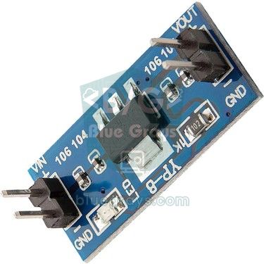
Here's an important fact: most ceramic SMD capacitors (MLCCs) carry no marking at all. You can only find the value of these little brown, beige or grey blocks from the reel label or with a multimeter that measures capacitance. The 106 and 104 you saw on the AMS1117 board above are printed on the board, not on the capacitors. On older parts or from some manufacturers you may find a two character code made of a letter and a digit: the letter gives the E24 value (A = 1.0, E = 1.5, J = 2.2, N = 3.3, S = 4.7, W = 6.8) and the digit the number of zeros in pF, so S3 = 4.7 × 1,000 pF = 4.7 nF. The X7R, X5R and C0G (NP0) on the reel label are dielectric types: C0G barely changes with temperature, while X7R and X5R can lose a large part of their capacitance as the applied DC voltage rises.
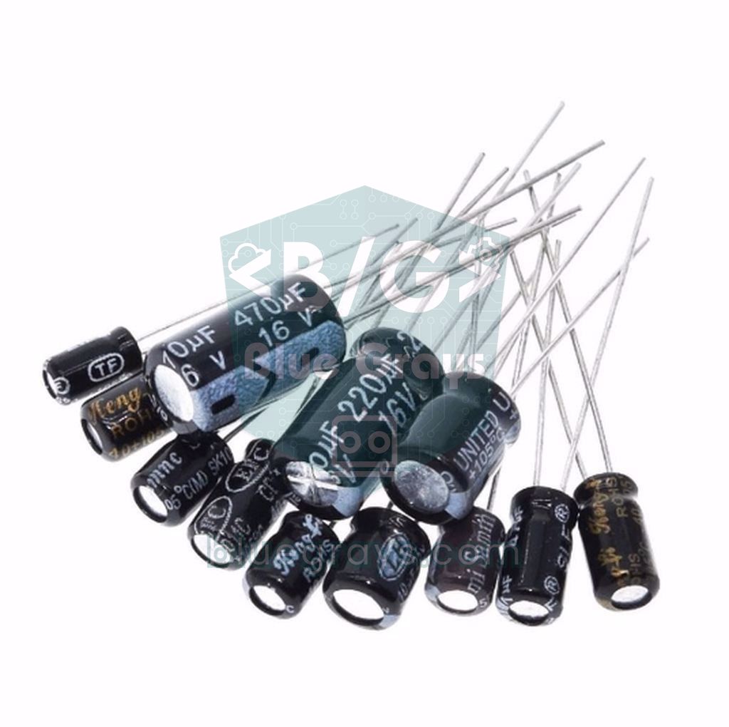
Tantalum capacitors usually have a yellow, orange or black rectangular body. They carry a pF code (106 = 10 µF, 476 = 47 µF, 107 = 100 µF) and often a voltage letter: J = 6.3 V, A = 10 V, C = 16 V, D = 20 V, E = 25 V, V = 35 V. Some manufacturers print the voltage directly instead of a letter. SMD aluminium electrolytics are small metal cans; the value is printed directly in µF and the black half-moon on top marks the negative (−) terminal. Markings like 2A104J on film and larger ceramic capacitors split into three parts: 2A = 100 V, 104 = 100 nF, J = ±5%. Other common voltage codes are 1C = 16 V, 1E = 25 V, 1H = 50 V and 2J = 630 V. You'll find more about capacitor types in What Is a Capacitor?.
SMD transistor and diode codes (1AM, J3Y, A7, M7)
The full part number doesn't fit on small packages like SOT-23, so transistors and diodes carry a 2–3 character marking code. These codes don't follow a single standard: the same code can mean completely different parts from two manufacturers, and a small letter at the end is usually a factory or date code. When identifying a part, use three clues together: the package type, the marking code and the part's job in the circuit. For bipolar transistors the SOT-23 pin order is usually 1 = base, 2 = emitter, 3 = collector; for MOSFETs such as the 2N7002 it's 1 = gate, 2 = source, 3 = drain. For pinouts and equivalents see the Transistors tool, and for how they work read What Is a Transistor?.
| Code | Package | Part | What it is |
|---|---|---|---|
| 1AM | SOT-23 | MMBT3904 | NPN transistor (SMD version of the 2N3904) |
| 2A | SOT-23 | MMBT3906 | PNP transistor (SMD version of the 2N3906) |
| 1P | SOT-23 | MMBT2222A | NPN transistor |
| 1F | SOT-23 | BC847B | NPN transistor (BC547B equivalent) |
| 3F | SOT-23 | BC857B | PNP transistor (BC557B equivalent) |
| J3Y | SOT-23 | S8050 | NPN transistor, very common on modules |
| 2TY | SOT-23 | S8550 | PNP transistor |
| 702 | SOT-23 | 2N7002 | N-channel small-signal MOSFET |
| A7 | SOT-23 | BAV99 | Dual switching diode in series |
| T4 | SOD-123 | 1N4148W | Fast switching diode |
| M7 | SMA | 1N4007 equivalent | 1 A, 1000 V rectifier diode |
| SS14 | SMA | SS14 | 1 A, 40 V Schottky diode |
Measuring an unmarked or unreadable resistor: an Arduino ohmmeter
If the code has worn off, the part is an 0402 or you're not sure of the result, the most reliable way is to measure it. When measuring with a multimeter, remove the resistor from the circuit if you can, or at least lift one end; parallel paths in the circuit make the reading lower than the real value. If you don't have a multimeter, you can build a simple ohmmeter with an Arduino. The circuit is a voltage divider: you connect a reference resistor of known value (Rref) in series with the resistor to be measured (Rx) and read the voltage at the midpoint with an analog pin. Because the Arduino's analog reading is ratiometric to the supply voltage, the formula is very simple: Rx = Rref × reading / (1024 − reading). You get the most accurate result when Rx is close to Rref: with a 10 kΩ reference you can measure resistors between 1 kΩ and 100 kΩ to about ±2%. Use a 1 kΩ reference for values around 100 Ω and a 1 MΩ reference for megohms, and update the RREF constant; measuring the reference's real value once with a multimeter and putting it in the code noticeably improves accuracy.
| Connection | Arduino Uno | ESP32 | Raspberry Pi Pico |
|---|---|---|---|
| Top end of Rref | 5V | 3V3 | 3V3(OUT) |
| Junction of Rref and Rx | A0 | GPIO 34 | GP26 (ADC0) |
| Bottom end of Rx | GND | GND | GND |
1// Basit ohmmetre: 5V - Rref - A0 - Rx - GND / Simple ohmmeter: 5V - Rref - A0 - Rx - GND
2const float RREF = 10000.0;   // bilinen direnç, multimetreyle ölçtüğün değeri yaz / known resistor, enter its measured value
3const int OLCUM_PIN = A0;
4
5void setup() {
6  Serial.begin(9600);
7}
8
9void loop() {
10  long toplam = 0;
11  for (int i = 0; i < 16; i++) {          // 16 okumanın ortalaması / average of 16 readings
12    toplam += analogRead(OLCUM_PIN);
13    delay(2);
14  }
15  float ham = toplam / 16.0;
16
17  if (ham > 1018) {
18    Serial.println(F("Acik devre / Open circuit"));
19  } else if (ham < 2) {
20    Serial.println(F("Kisa devre / Short circuit"));
21  } else {
22    float rx = RREF * ham / (1024.0 - ham); // Rx = Rref * ham / (1024 - ham)
23    Serial.print(F("Rx = "));
24    if (rx >= 1000) {
25      Serial.print(rx / 1000.0, 2);
26      Serial.println(F(" kOhm"));
27    } else {
28      Serial.print(rx, 1);
29      Serial.println(F(" Ohm"));
30    }
31  }
32  delay(1000);
33}
Let the Arduino do it: an SMD code decoder in the Serial Monitor
The program below applies every resistor rule in this article: it understands 3 and 4 digit codes, R notation, EIA-96 and 0 ohm jumpers. Open the Serial Monitor at 9600 baud with the "Newline" line ending, type a code such as 4702 or 68X and press Enter. Because the letter R can be both a decimal point and an EIA-96 multiplier, the program treats codes containing R as decimal notation first (47R = 47 Ω); the SMD code tool follows the same rule. The E96 table is kept in flash with PROGMEM, so it doesn't use up the Uno's 2 KB of RAM. The code also compiles and runs on the ESP32 without any changes. If you're using the Serial Monitor for the first time, have a look at Arduino Serial Monitor.
1// SMD direnç kodu çözücü: Seri Monitör'e kodu yaz, değeri gör / SMD resistor code decoder: type a code in the Serial Monitor, see the value
2const uint16_t E96[96] PROGMEM = {
3  100, 102, 105, 107, 110, 113, 115, 118, 121, 124, 127, 130, 133, 137, 140, 143,
4  147, 150, 154, 158, 162, 165, 169, 174, 178, 182, 187, 191, 196, 200, 205, 210,
5  215, 221, 226, 232, 237, 243, 249, 255, 261, 267, 274, 280, 287, 294, 301, 309,
6  316, 324, 332, 340, 348, 357, 365, 374, 383, 392, 402, 412, 422, 432, 442, 453,
7  464, 475, 487, 499, 511, 523, 536, 549, 562, 576, 590, 604, 619, 634, 649, 665,
8  681, 698, 715, 732, 750, 768, 787, 806, 825, 845, 866, 887, 909, 931, 953, 976
9};
10
11// EIA-96 harf çarpanı; bilinmeyen harfte -1 / EIA-96 letter multiplier; -1 for an unknown letter
12float eiaCarpan(char c) {
13  switch (c) {
14    case 'Z': return 0.001;
15    case 'Y': case 'R': return 0.01;
16    case 'X': case 'S': return 0.1;
17    case 'A': return 1;
18    case 'B': case 'H': return 10;
19    case 'C': return 100;
20    case 'D': return 1000;
21    case 'E': return 10000;
22    case 'F': return 100000;
23    default: return -1;
24  }
25}
26
27// Kodu ohma çevirir, geçersizse -1 döner / Converts the code to ohms, returns -1 if invalid
28float smdCoz(String kod) {
29  kod.trim();
30  kod.toUpperCase();
31  int n = kod.length();
32  if (n == 0 || n > 5) return -1;
33
34  int r = kod.indexOf('R');
35  if (r >= 0) {                                  // R ondalık virgüldür: 4R7, R47, 47R / R is the decimal point
36    if (kod.lastIndexOf('R') != r || n < 2) return -1;
37    for (int i = 0; i < n; i++) {
38      if (i != r && !isDigit(kod[i])) return -1;
39    }
40    kod.replace('R', '.');
41    return kod.toFloat();                        // "4.7" -> 4.7, ".47" -> 0.47
42  }
43
44  if (n == 3 && isDigit(kod[0]) && isDigit(kod[1]) && isAlpha(kod[2])) {   // EIA-96: 01C
45    int sira = kod.substring(0, 2).toInt();
46    float carpan = eiaCarpan(kod[2]);
47    if (sira < 1 || sira > 96 || carpan < 0) return -1;
48    return pgm_read_word(&E96[sira - 1]) * carpan;
49  }
50
51  for (int i = 0; i < n; i++) {
52    if (!isDigit(kod[i])) return -1;
53  }
54  if (n <= 2) return kod.toInt() == 0 ? 0 : -1;  // 0 ya da 00: köprü direnci / 0 or 00: jumper
55  long taban = kod.substring(0, n - 1).toInt();  // 3 hane: 2 rakam, 4 hane: 3 rakam / significant digits
56  int sifir = kod[n - 1] - '0';                  // son hane: sıfır sayısı / last digit: number of zeros
57  float deger = taban;
58  for (int i = 0; i < sifir; i++) deger *= 10;
59  return deger;
60}
61
62void ohmYaz(float r) {
63  if (r >= 1e6) { Serial.print(r / 1e6, 3); Serial.println(F(" MOhm")); }
64  else if (r >= 1e3) { Serial.print(r / 1e3, 3); Serial.println(F(" kOhm")); }
65  else { Serial.print(r, 3); Serial.println(F(" Ohm")); }
66}
67
68void setup() {
69  Serial.begin(9600);
70  Serial.println(F("SMD kodunu yaz (or. 103, 4702, 4R7, 01C) / Type an SMD code"));
71}
72
73void loop() {
74  if (Serial.available()) {
75    String kod = Serial.readStringUntil('\n');
76    kod.trim();
77    if (kod.length() == 0) return;
78    float r = smdCoz(kod);
79    Serial.print(kod);
80    Serial.print(F(" = "));
81    if (r < 0) Serial.println(F("gecersiz kod / invalid code"));
82    else ohmYaz(r);
83  }
84}
Measuring with the ESP32 and Raspberry Pi Pico
To use the ohmmeter code on an ESP32, change the measuring pin to 34 and connect the top end of Rref to the 3V3 pin. GPIO 34 belongs to the ADC1 group, which keeps working while Wi-Fi is on. Unlike the Uno, the ESP32's ADC isn't ratiometric to its supply voltage and isn't linear near the ends of its range, so simply replacing 1024 with 4096 in the formula can give errors of more than 10 percent. Use analogReadMilliVolts(), which returns calibrated millivolts, instead, and write the formula as Rx = Rref × V / (3300 − V), with V in millivolts; entering the voltage you measured on the 3V3 pin with a multimeter instead of 3300 improves the result further. Because the ADC saturates at around 3.1 V, lower the open circuit threshold to about 3000 mV and keep the measured resistor close to the reference. On the Raspberry Pi Pico, the MicroPython code below both decodes SMD codes and measures resistance on GP26. The Pico's read_u16() returns a value from 0 to 65535, so the 1024 in the formula becomes 65535 here. If you're new to the Pico, start with What Is the Raspberry Pi Pico?.
1from machine import ADC
2import time
3
4E96 = [100, 102, 105, 107, 110, 113, 115, 118, 121, 124, 127, 130, 133, 137, 140, 143,
5       147, 150, 154, 158, 162, 165, 169, 174, 178, 182, 187, 191, 196, 200, 205, 210,
6       215, 221, 226, 232, 237, 243, 249, 255, 261, 267, 274, 280, 287, 294, 301, 309,
7       316, 324, 332, 340, 348, 357, 365, 374, 383, 392, 402, 412, 422, 432, 442, 453,
8       464, 475, 487, 499, 511, 523, 536, 549, 562, 576, 590, 604, 619, 634, 649, 665,
9       681, 698, 715, 732, 750, 768, 787, 806, 825, 845, 866, 887, 909, 931, 953, 976]
10EIA = {"Z": 0.001, "Y": 0.01, "R": 0.01, "X": 0.1, "S": 0.1, "A": 1,
11       "B": 10, "H": 10, "C": 100, "D": 1000, "E": 10000, "F": 100000}
12
13def smd_coz(kod):
14    kod = kod.strip().upper()
15    if "R" in kod:                                    # R ondalık virgüldür: 4R7, R47 / R is the decimal point
16        if kod.count("R") != 1 or not kod.replace("R", "").isdigit():
17            return None
18        return float(kod.replace("R", "."))
19    if len(kod) == 3 and kod[:2].isdigit() and kod[2] in EIA:   # EIA-96: 01C
20        sira = int(kod[:2])
21        return E96[sira - 1] * EIA[kod[2]] if 1 <= sira <= 96 else None
22    if kod.isdigit():
23        if len(kod) <= 2:
24            return 0.0 if int(kod) == 0 else None     # 0 ya da 00: köprü / 0 or 00: jumper
25        return int(kod[:-1]) * 10 ** int(kod[-1])     # son hane sıfır sayısı / last digit = number of zeros
26    return None
27
28def ohm_yaz(r):
29    if r >= 1e6:
30        return "{:.3g} MOhm".format(r / 1e6)
31    if r >= 1e3:
32        return "{:.3g} kOhm".format(r / 1e3)
33    return "{:.3g} Ohm".format(r)
34
35adc = ADC(26)                  # GP26 = ADC0
36RREF = 10000                   # 3V3 ile GP26 arasındaki bilinen direnç / known resistor between 3V3 and GP26
37
38def olc():
39    toplam = 0
40    for _ in range(32):        # 32 okumanın ortalaması / average of 32 readings
41        toplam += adc.read_u16()
42        time.sleep_ms(2)
43    ham = toplam / 32
44    if ham > 65000:
45        return None            # açık devre / open circuit
46    return RREF * ham / (65535 - ham)
47
48for kod in ("103", "4702", "4R7", "01C", "68X"):
49    print(kod, "=", ohm_yaz(smd_coz(kod)))
50
51while True:
52    rx = olc()
53    print("Rx =", ohm_yaz(rx) if rx is not None else "acik devre / open circuit")
54    time.sleep(1)
Common mistakes and how to fix them
| Mistake | Why it happens | Fix |
|---|---|---|
| Taking a resistor marked 100 as 100 Ω | The last digit is the number of zeros | 100 = 10 Ω; 100 Ω is written 101 or 1000 |
| Taking 01C as 100 Ω | An EIA-96 code is a position number | 01 = 100, C = × 100; the result is 10 kΩ |
| Assuming every part marked 104 is 100 kΩ | Capacitor codes are in pF | Identify the part type; on a capacitor 104 = 100 nF |
| The value reads low in the circuit | Other parts connected in parallel | Remove the resistor or lift one end before measuring |
| The parts you ordered are tiny | Imperial and metric 0603 mixed up | Check the metric equivalent (1608) when ordering |
| A tantalum capacitor got hot | It was fitted backwards | The banded end is positive; replace the part |
| The code gives a nonsensical value | Read upside down, or it isn't a resistor | Turn it 180 degrees and read again; measure if needed |
Ideas for practising with SMD codes
- Inspect your board: Read the codes of the resistors on your Arduino Nano or ESP32 board; find the 102 or 103 codes next to the LEDs and work out which resistor feeds which LED.
- Ohmmeter with a display: Combine the ohmmeter above with an I2C LCD display to make a portable resistance meter.
- Capacitance meter: Find the value of unmarked ceramic capacitors by charging them through a resistor and measuring the RC time constant; the method is in What Is a Capacitor?.
- Your own PCB: Design your first PCB with 0805 resistors and capacitors; the steps are in PCB design with EasyEDA.
- Battery voltage meter: Build a divider from two SMD resistors and measure a 9 V battery with an Arduino; pick the resistors with the Voltage divider tool.
- Tidy parts box: Store the SMD parts you desolder in boxes labelled with their codes; measure unmarked parts and write the value on the label.
Reading SMD codes may look like cracking a cipher at first, but once you learn a few rules every resistor and capacitor on a board starts telling you what it does. If you want to revisit how colour-banded resistors work, take a look at What Is a Resistor?. In the BlueGrays app you'll find projects where resistors play a key role, from lighting an LED and measuring light with an LDR to NTC temperature measurement and a digital voltmeter, each with step-by-step circuit diagrams and code.
Frequently asked questions
What does 103 mean on an SMD resistor?
103 means 10 followed by three zeros: 10,000 Ω, or 10 kΩ. In three digit codes the first two digits are the value and the last digit is the number of zeros. The same 10 kΩ resistor may be marked 1002 in its 1% version, or 01C with the EIA-96 code in the 0603 size.
How many ohms is an SMD resistor marked 100?
A code of 100 is 10 Ω, not 100 Ω: it's 10 followed by no zeros. A 100 Ω resistor is marked 101 in the three digit code and 1000 in the four digit code. This is the most common mistake when reading SMD codes.
What value is an 01C SMD resistor?
01C is an EIA-96 code and corresponds to 10 kΩ. 01 stands for 100, the first value of the E96 series, and the letter C is the × 100 multiplier. These codes are used on 1% resistors in the 0603 size, and the value can only be read from a table or a code decoder tool.
What does 104 mean on a capacitor?
104 means 10 followed by four zeros in picofarads: 100,000 pF = 100 nF = 0.1 µF. However, most ceramic SMD capacitors have no marking at all; you'll usually see 104 on through-hole disc capacitors, tantalum capacitors or printed on the board.
What's the difference between 0805 and 1206 SMD resistors?
The difference is the size, and with it the power rating. An 0805 is about 2.0 × 1.25 mm and typically rated 1/8 W, while a 1206 is 3.2 × 1.6 mm and 1/4 W. Their values use the same codes; the 1206 is more comfortable for circuits that dissipate more power and for hand soldering.
How do you measure an SMD resistor with no marking?
Set your multimeter to the ohms range and, if possible, measure the resistor after removing it from the circuit, because parallel paths make the reading low. Resistors of size 0402 and smaller have no printed code, so measuring is the only option. Without a multimeter you can build a simple ohmmeter on an Arduino using a known reference resistor.
Projects to build after reading this
See all projects
LED Blink
The very first hello of electronics: switching a single LED on and off. The Arduino turns the LED on and off at short intervals, so the light blinks quickly. You see in the simplest way how the board

Measuring Light Intensity with an LDR
Want to see how bright your room is as a number? The LDR, a small part that reacts to light, measures the light around it, and the Arduino writes the value to your computer screen every half second. C

LED Blink with ESP32
Teaches basic GPIO output usage with ESP32. We achieve a blinking effect by turning an LED on and off from a digital pin. ESP32 version of the classic blink project on Arduino UNO; the basic blink commands in the Arduino environment are the same, but the ESP32's pin layout and 3.3 V GPIO levels differ from those of the Arduino UNO.

Reading Light Intensity with the ESP32 LDR Module
Real-time monitoring of the LDR module's raw ADC value and relative light percentage calculated from dark and light reference values in the Serial Monitor. This percentage is not a lux measurement. Teaches the module’s calibration logic. It is ideal to complete this before Project 10, as it is used to determine the threshold value.
Raspberry Pi Pico: Controlling an External LED (Breadboard)
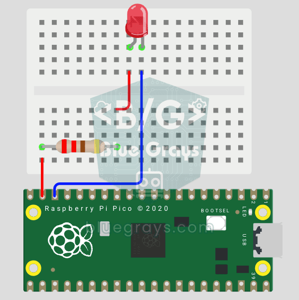
The next step after Pico’s built-in LED: connecting an external LED to the breadboard and controlling it via the GP14 pin. In this project, you’ll learn how to use any of the Pico’s general-purpose GPIO pins as an output, the LED’s polarity (long leg = anode/+, short leg = cathode/–), and why a current-limiting resistor (220Ω) is required. If you don’t include the resistor, excessive current will flow through the LED and it may burn out. The circuit is very simple: Pico GP14 → 220Ω resistor → LE
Digital Voltmeter with LCD Display
Find out how much voltage a battery or power adapter gives with a meter you built yourself. A divider made of two resistors brings high voltage down to a level the board can read, and the Arduino calc
Temperature Measurement with NTC and 2x16 Lcd Display
Measure the temperature around you with a sensor that looks like a tiny bead. This part, called an NTC, lets electricity through more easily as it warms up; the Arduino reads that change, turns it int
Using an RGB LED
Three colours hide inside a single LED: the RGB LED lights up red, then green, then blue, each colour on for half a second and off for half a second, before the cycle starts again. All you need is one