
How to Calculate LED Resistor Value: Formula and Chart
How do you calculate an LED resistor? The R = (Vsupply - Vled) / I formula, forward voltage by colour, ready values for 5 V and 3.3 V, plus series wiring.
Calculating the LED resistor is the first step to running an LED at the right brightness without burning it out or overloading your board's pin. The rule is a single formula: R = (Vsupply − Vled) / I. You subtract the LED's forward voltage from the supply voltage and divide the remaining voltage by the current you want; the result is the resistor value you need, in ohms. For example, if you want to run a red LED at 20 mA from the 5 V output of an Arduino Uno, you get (5 − 2) / 0.02 = 150 Ω.
In this post you'll see why an LED must always be connected with a resistor, the forward voltage values by colour, ready-made resistor tables for 5 V (Arduino Uno, Nano, Mega) and 3.3 V (ESP32, Raspberry Pi Pico), the calculations for wiring several LEDs in series and in parallel, and the mistakes beginners make most often. If you don't want to do the maths by hand, the LED resistor calculator applies the same formula for you.
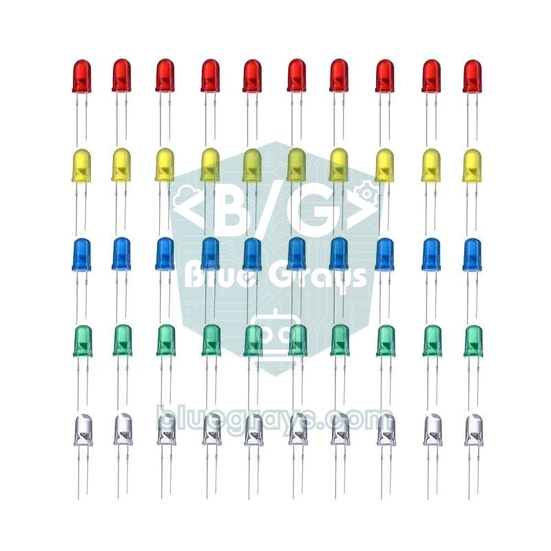
Why does an LED need a resistor?
An LED is a diode and doesn't behave like a light bulb. The filament in a bulb gets more resistant as it heats up, so it limits its own current to some extent. An LED is different: below its forward voltage almost no current flows, and once that threshold is passed the current rises exponentially with voltage. A red LED draws only a few milliamps at around 1.8 V but reaches 20 mA at around 2.0 V; raise the voltage by a few hundred millivolts more and the current goes far beyond what the LED can take.
On top of that, an LED's forward voltage drops a little as it warms up, which makes it draw more current at the same voltage and heat up even more. This vicious circle is called thermal runaway. A series resistor breaks the cycle: as the current rises, the voltage drop across the resistor rises too, and the voltage left for the LED limits itself. If you connect an LED straight to 5 V with no resistor, the current is determined only by the internal resistance of the supply, the wires and the pin. The result is either an LED that fails instantly or an Arduino pin that is slowly damaged. On the ATmega328P the absolute maximum per pin is 40 mA, and for continuous use you are advised not to exceed 20 mA per pin.
LED resistor calculation formula
The formula is Ohm's Law (R = V / I) adapted to an LED. In a series circuit the supply voltage is shared between the LED and the resistor: the LED takes its own forward voltage (Vf) and the rest drops across the resistor. Because the current through the resistor is the same as the current through the LED, the resistor value is the voltage across it divided by the desired current. Let's go through an example: you connect a red LED to the Uno's 5 V output; Vsupply = 5 V, Vled = 2.0 V, I = 20 mA = 0.02 A. The voltage across the resistor is 5 − 2 = 3 V, and R = 3 / 0.02 = 150 Ω. If you want to reduce the current to 10 mA you get R = 3 / 0.01 = 300 Ω; since that value isn't in the common E12 series, you pick the next one up, 330 Ω, and the actual current becomes 3 / 330 ≈ 9.1 mA. The most common calculation mistake is units: if you type 20 mA into the formula as 20, you get a meaningless result like 0.15 Ω. Always convert the current to amps, or take the current in milliamps and read the result in kilohms (3 V / 20 mA = 0.15 kΩ = 150 Ω).
| Symbol | Meaning | Typical value |
|---|---|---|
| R | Value of the resistor to fit (Ω) | Calculated |
| Vsupply | Voltage powering the LED (pin output or power supply) | 5 V, 3.3 V, 9 V, 12 V |
| Vled (Vf) | LED forward voltage, depends on colour | 1.8–3.4 V |
| I | Current you want through the LED (amps) | 0.005–0.020 A (5–20 mA) |
| P | Power dissipated by the resistor: P = (Vsupply − Vled) × I | 0.01–0.2 W |
LED forward voltage table by colour
Forward voltage depends on the semiconductor material the LED is made of, and therefore on the colour of light it emits. As the wavelength gets shorter, going from red towards blue, the photon energy increases, so the forward voltage rises too. Red, orange, yellow and classic yellowish-green LEDs are usually made from materials such as AlGaInP or GaP and work at around 2 V. Blue, bright green and white LEDs are InGaN-based and go above 3 V. A white LED is really a blue LED coated with yellow phosphor, so its forward voltage is very close to that of blue.
| Colour | Wavelength (approx.) | Forward voltage range | Typical value for calculations |
|---|---|---|---|
| Infrared (IR) | 850–940 nm | 1.2–1.6 V | 1.3 V |
| Red | 620–630 nm | 1.8–2.2 V | 2.0 V |
| Orange | 600–610 nm | 1.9–2.2 V | 2.0 V |
| Yellow | 585–595 nm | 2.0–2.2 V | 2.1 V |
| Green (classic, yellowish) | 565–570 nm | 2.0–2.4 V | 2.2 V |
| Green (bright, pure) | 520–530 nm | 2.8–3.4 V | 3.1 V |
| Blue | 460–470 nm | 2.8–3.4 V | 3.1 V |
| White | Broad spectrum | 2.8–3.4 V | 3.2 V |
| Violet / UV | 395–405 nm | 3.0–3.6 V | 3.3 V |
The values in the table are typical forward voltages at about 20 mA. Even two LEDs of the same colour can differ by a few hundred millivolts depending on the manufacturer and production batch; forward voltage also changes a little with current. If you have the LED's datasheet, use the Vf value there; if not, use the typical value from the table. You can measure the forward voltage of an unknown LED with your multimeter's diode range; because that range measures with a very low current, it shows a slightly low value. The LED voltages tool is also handy for looking up values by colour quickly. Taking Vf smaller than it really is gives a larger resistor and keeps you on the safe side.
Ready values for 5 V (Arduino Uno, Nano, Mega)
| LED colour | Vf | Calculation for 20 mA | Standard (actual current) | Calculation for 10 mA | Standard (actual current) |
|---|---|---|---|---|---|
| Red | 2.0 V | 150 Ω | 150 Ω (20 mA) | 300 Ω | 330 Ω (9.1 mA) |
| Yellow | 2.1 V | 145 Ω | 150 Ω (19.3 mA) | 290 Ω | 330 Ω (8.8 mA) |
| Green (classic) | 2.2 V | 140 Ω | 150 Ω (18.7 mA) | 280 Ω | 330 Ω (8.5 mA) |
| Blue | 3.1 V | 95 Ω | 100 Ω (19 mA) | 190 Ω | 220 Ω (8.6 mA) |
| White | 3.2 V | 90 Ω | 100 Ω (18 mA) | 180 Ω | 180 Ω (10 mA) |
| Violet / UV | 3.3 V | 85 Ω | 100 Ω (17 mA) | 170 Ω | 180 Ω (9.4 mA) |
The standard values in the table are the calculated results rounded up to the next E12 value; the actual current with that resistor is in brackets. In practice most people use 220 Ω or 330 Ω for every colour, and that's a sound choice. At 5 V, with 220 Ω a red LED draws about 13.6 mA and a blue LED about 8.6 mA; with 330 Ω these drop to 9.1 mA and 5.8 mA. Today's efficient LEDs are bright enough even at 5–10 mA, so going up to 20 mA is often unnecessary; the LED runs cooler, lasts longer and your board's current budget is eased. This matters especially in projects that drive many LEDs, because the total current through the ATmega328P's VCC and GND pins is limited to 200 mA.
Ready values for 3.3 V (ESP32, Raspberry Pi Pico)
The ESP32 and Raspberry Pi Pico pins output 3.3 V, so the voltage across the resistor is smaller and the calculation changes. The current limits of the two boards differ too. On the ESP32, up to about 20 mA per pin is safe, but if you're driving several LEDs at once, a 10 mA target is a bright and safe middle ground. The RP2040 on the Raspberry Pi Pico has its pin drive strength set to 4 mA by default (2, 4, 8 and 12 mA can be selected), and the total current of all GPIOs is limited to about 50 mA. So on the Pico it's best to aim for 3–5 mA per LED; with 330 Ω a red LED is already bright enough to see easily.
| LED colour | Vf | ESP32, 10 mA target | Pico, 4 mA target |
|---|---|---|---|
| Red | 2.0 V | 130 Ω → 150 Ω (8.7 mA) | 325 Ω → 330 Ω (3.9 mA) |
| Yellow | 2.1 V | 120 Ω → 120 Ω (10 mA) | 300 Ω → 330 Ω (3.6 mA) |
| Green (classic) | 2.2 V | 110 Ω → 120 Ω (9.2 mA) | 275 Ω → 330 Ω (3.3 mA) |
| Blue | 3.1 V | 20 Ω → 22 Ω (9.1 mA) | 50 Ω → 56 Ω (3.6 mA) |
| White | 3.2 V | 10 Ω → 10 Ω (10 mA) | 25 Ω → 27 Ω (3.7 mA) |
Several LEDs: wiring in series and in parallel
When you wire LEDs in series, the same current flows through all of them and their forward voltages add up. The formula expands to: R = (Vsupply − n × Vled) / I, where n is the number of LEDs in series. For example, if you want to wire three white LEDs in series from a 12 V adapter and run 20 mA, 12 − 3 × 3.2 = 2.4 V is left and R = 2.4 / 0.02 = 120 Ω. The advantage of a series connection is that a single resistor limits the whole string and most of the energy is used in the LEDs rather than the resistor. The thing to watch is that the sum of the forward voltages doesn't get too close to the supply. At 5 V, two red LEDs (2 × 2.0 = 4 V) work on the edge; about 18 mA flows with 56 Ω, but small differences between the LEDs change the current noticeably. Two blue LEDs (6.2 V) at 5 V won't light at all. Designing so that at least 1–2 V is left across the resistor keeps the circuit stable. To work out resistor combinations, see the series and parallel resistor calculation post.
In a parallel connection each LED sees the full supply and the currents add up. The golden rule here is: give every LED its own resistor. If you connect several LEDs in parallel and use a single resistor, the LED with a slightly lower forward voltage takes most of the current, heats up, its forward voltage drops even further and it eventually fails; then the same load lands on the next LED. Connecting different colours in parallel with one resistor is even worse: the red LED starts conducting at around 2.0 V, so the blue LED never gets the chance to reach 3.1 V and never lights. With separate resistors the current of each LED is calculated independently; at 5 V, four red LEDs with 220 Ω resistors draw about 4 × 13.6 ≈ 54 mA in total. That's too much for a single Arduino pin; you should power the LEDs from the 5 V rail and switch them from the pin with an NPN transistor or a MOSFET.
| Connection | Resistor | Advantage | Disadvantage |
|---|---|---|---|
| Series | One resistor: (V − n × Vf) / I | Same current in all, efficient, few parts | If one LED fails they all go out; needs a higher supply voltage |
| Parallel, separate resistor per LED | Each: (V − Vf) / I | Works at low voltage, LEDs are independent of each other | Total current grows, more power is dissipated in the resistors |
| Parallel, one shared resistor | Not recommended | Saves one part | Current imbalance, LEDs fail one by one |
Resistor power rating: what wattage do I need?
A resistor turns the voltage across it into heat. The power it dissipates is found with P = (Vsupply − Vled) × I or the equivalent P = I² × R. For a red LED at 5 V with 150 Ω and 20 mA, P = 3 × 0.02 = 0.06 W; a standard 1/4 W (0.25 W) resistor handles that easily. If you're driving a single red LED at 12 V, things change: 10 V drops across the resistor, R = 10 / 0.02 = 500 Ω and you pick 560 Ω. The current is about 17.9 mA and the power about 0.18 W. Since that is close to the 1/4 W limit, the resistor gets noticeably warm; it's better to choose a 1/2 W resistor or to wire the LEDs in series to reduce the wasted voltage. As a general rule, run a resistor at no more than half its rated power. For details, see the electrical power calculation post and the Ohm's Law calculator.
Step by step: connecting an LED to Arduino with a resistor
- Determine the LED's colour and find its forward voltage from the table; 2.0 V for red.
- Choose the supply voltage and target current; 5 V and 10–15 mA is a good start for an Arduino Uno.
- Calculate the resistor with the formula and round up to the next standard value; for a red LED at 5 V, 220 Ω (red, red, brown) is suitable. You can check the colour code in the resistor colour codes post.
- Connect the LED's long leg (anode) to one end of the resistor, and the other end of the resistor to Arduino pin 9.
- Connect the LED's short leg (cathode, the side with the flat edge on the body) to GND. The resistor can be on the anode or the cathode side; as long as it's in series the result is the same.
- Upload the code below; if you like, connect a multimeter in series with the circuit on its current range to measure the actual current.
1const int LED_PIN = 9;   // 220 Ω direnç üzerinden LED / LED through a 220 Ω resistor
2
3void setup() {
4  pinMode(LED_PIN, OUTPUT);       // pini çıkış yap / set pin as output
5}
6
7void loop() {
8  digitalWrite(LED_PIN, HIGH);    // tam parlaklık / full brightness
9  delay(1000);
10  analogWrite(LED_PIN, 64);       // yaklaşık %25 PWM ile kısık / dimmed with about 25% PWM
11  delay(1000);
12  digitalWrite(LED_PIN, LOW);     // söndür / turn off
13  delay(1000);
14}
The code first lights the LED at full brightness, then dims it with analogWrite at about a 25% duty cycle, and finally turns it off. Pin 9 is one of the PWM-capable pins on the Uno (3, 5, 6, 9, 10 and 11). An important detail: PWM doesn't change the resistor calculation. In PWM the pin switches on and off very quickly, and every time it's on, the peak current the resistor allows (about 13.6 mA in this example) flows through the LED; what lowers the brightness is the reduced average current. That's why the resistor is always calculated for the fully on state. You'll find the details of PWM in the what is PWM post.
LED on the ESP32 and Raspberry Pi Pico
On the ESP32 the same wiring and the same Arduino code work; recent ESP32 Arduino core versions support the analogWrite function too. You just need to change the pin number, for example to GPIO 18, and choose the resistor from the 3.3 V table; 150–220 Ω suits a red LED. On the Raspberry Pi Pico you can fade the LED smoothly in and out through PWM with MicroPython. In the example below the LED is connected to pin GP15 with a 330 Ω resistor, so the current stays within the default 4 mA drive strength.
1from machine import Pin, PWM
2import time
3
4led = PWM(Pin(15))          # GP15 -> 330 ohm -> LED -> GND / GP15 -> 330 ohm -> LED -> GND
5led.freq(1000)              # 1 kHz PWM frekansı / 1 kHz PWM frequency
6
7while True:
8    for duty in range(0, 65536, 1024):      # yavaşça aydınlat / fade in
9        led.duty_u16(duty)
10        time.sleep_ms(10)
11    for duty in range(65535, -1, -1024):    # yavaşça söndür / fade out
12        led.duty_u16(duty)
13        time.sleep_ms(10)
LED resistor calculation project ideas
- Traffic light: Connect red, yellow and green LEDs with separate resistors; since the forward voltages of these colours are close to each other, 220 Ω suits all three. Details are in the Arduino traffic light post.
- Knight Rider effect: Connect six or eight LEDs to different pins, each with its own resistor, and light them in sequence; see Knight Rider and chasing LEDs.
- Colour mixing with an RGB LED: Adjust the colour balance by choosing a slightly larger resistor for the red channel and smaller ones for the blue and green channels; take a look at using an RGB LED.
- Night light: Light white LEDs when the room gets dark using an LDR; at 5 V, 100–150 Ω is enough for a white LED.
- 7-segment display: Each segment is a separate LED, so every segment needs its own resistor; see 7-segment display.
- Lots of LEDs: If you run out of pins, use a 74HC595 shift register; still put a resistor on every output and don't exceed the chip's total current limit.
Common mistakes and how to fix them
| Mistake | Symptom | Fix |
|---|---|---|
| No resistor fitted | The LED flashes very bright then goes dark or fails immediately, the pin gets hot | Add a series current-limiting resistor to every LED |
| Typing the current in mA into the formula | The result is meaningless, like 0.15 Ω | 20 mA = 0.02 A; convert the current to amps |
| Resistor far too large (e.g. 10 kΩ) | The LED doesn't light or is barely visible | At 5 V, 10 kΩ gives only 0.3 mA; stay in the 220 Ω–1 kΩ range |
| Misreading the colour code | 2.2 kΩ fitted instead of 220 Ω, LED very dim | Red-red-brown is 220 Ω, red-red-red is 2.2 kΩ; measure with a multimeter |
| One resistor for parallel LEDs | One LED is bright, the others dim; the LEDs fail over time | Give each LED its own resistor or wire the LEDs in series |
| LED fitted backwards | The LED doesn't light at all | Long leg (anode) to positive, short leg and flat edge (cathode) to GND |
| Thinking pin 13 has a built-in resistor | An external LED draws excess current | The on-board LED has its own circuit; an external LED on pin 13 still needs a resistor |
| Connecting a blue or white LED at 3.3 V with no resistor | Brightness varies from board to board, the pin is stressed | Use at least 33–47 Ω or drive it from 5 V with a transistor |
Once you grasp the logic, calculating an LED resistor takes seconds: find the colour, subtract the forward voltage from the supply voltage, divide by the current you want and round up to the next standard value. Just remember 220–330 Ω at 5 V, 330 Ω on the Pico, a small but definitely present resistor for blue and white LEDs at 3.3 V, and a separate resistor for every LED in a parallel connection. In the BlueGrays app you can try step by step the Arduino, ESP32 and Pico versions of projects such as blinking an LED, traffic lights, chasing LEDs and Knight Rider, with circuit diagrams and code drawn with the right resistor values.
Frequently asked questions
How many ohms of resistor does an LED need?
It depends on the supply voltage and the LED colour: R = (Vsupply − Vled) / I. On 5 V boards such as the Arduino Uno, 220–330 Ω is a safe and bright enough choice for almost any colour. On the ESP32 and Raspberry Pi Pico you can use 150–330 Ω for red, yellow and green LEDs and 33–68 Ω for blue and white LEDs.
What happens if I don't use a resistor with an LED?
Because an LED doesn't limit current itself, the current rises quickly at any voltage above its forward voltage. The LED can overheat and fail in a short time, change colour or have its life seriously shortened. Connected directly to an Arduino pin, the pin is also pushed past its 40 mA absolute limit and can be permanently damaged.
Should I use 220 ohm or 330 ohm?
Both are safe at 5 V. A 220 Ω resistor passes about 13.6 mA through a red LED and 330 Ω about 9.1 mA, and the brightness difference between them is barely noticeable by eye. If you'll be driving lots of LEDs or running on batteries, 330 Ω is the better choice because it draws less current.
Does the resistor go on the positive or negative leg of the LED?
It doesn't matter. As long as the LED and resistor are in series, the same current flows through both; the resistor limits the current the same way on the anode side or the cathode side. What matters is the LED's direction: the long leg (anode) goes to positive and the short leg (cathode) to GND.
How many ohms of resistor do I need for an LED on 12 V?
For a single red LED, R = (12 − 2) / 0.02 = 500 Ω, and you pick the next standard value up, 560 Ω. Since the resistor dissipates about 0.18 W, using a 1/2 W resistor is safer. If you wire three white LEDs in series, (12 − 9.6) / 0.02 = 120 Ω is enough and far less power is lost in the resistor.
Can I use one resistor for several LEDs?
Yes if the LEDs are in series; one resistor limits the whole string and the formula becomes R = (Vsupply − n × Vled) / I. Using one resistor for LEDs in parallel is not recommended, because the LED with the lower forward voltage takes most of the current and fails over time. In a parallel connection, give every LED its own resistor.
Projects to build after reading this
See all projects
LED Blink
The very first hello of electronics: switching a single LED on and off. The Arduino turns the LED on and off at short intervals, so the light blinks quickly. You see in the simplest way how the board

Two LEDs Blinking Alternately
Two LEDs blink quickly in turn: when one lights up the other goes off, as if they were tossing a ball back and forth. The Arduino keeps each light on for a fifth of a second and then hands over to the

Traffic Light
A tiny copy of the traffic light you see on the road every day. Red stays on for two seconds, yellow flashes for a moment, green stays on for two seconds, then it goes back to red through yellow again

LED Chaser
Lights that switch on one after another, as if they were running. The Arduino lights six LEDs one at a time; each glows for a brief moment and goes out, so the light walks from start to end and then s

Knight Rider LED Effect
The classic scanner light: a dot of light slides from one end of six LEDs to the other and then comes back. The Arduino lights each LED for a tenth of a second before moving on, turns around at each e

LED Blink with ESP32
Teaches basic GPIO output usage with ESP32. We achieve a blinking effect by turning an LED on and off from a digital pin. ESP32 version of the classic blink project on Arduino UNO; the basic blink commands in the Arduino environment are the same, but the ESP32's pin layout and 3.3 V GPIO levels differ from those of the Arduino UNO.
Raspberry Pi Pico: Controlling an External LED (Breadboard)
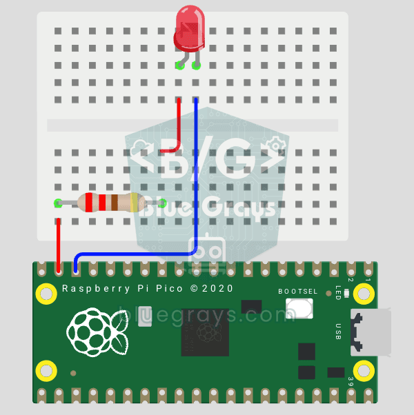
The next step after Pico’s built-in LED: connecting an external LED to the breadboard and controlling it via the GP14 pin. In this project, you’ll learn how to use any of the Pico’s general-purpose GPIO pins as an output, the LED’s polarity (long leg = anode/+, short leg = cathode/–), and why a current-limiting resistor (220Ω) is required. If you don’t include the resistor, excessive current will flow through the LED and it may burn out. The circuit is very simple: Pico GP14 → 220Ω resistor → LE
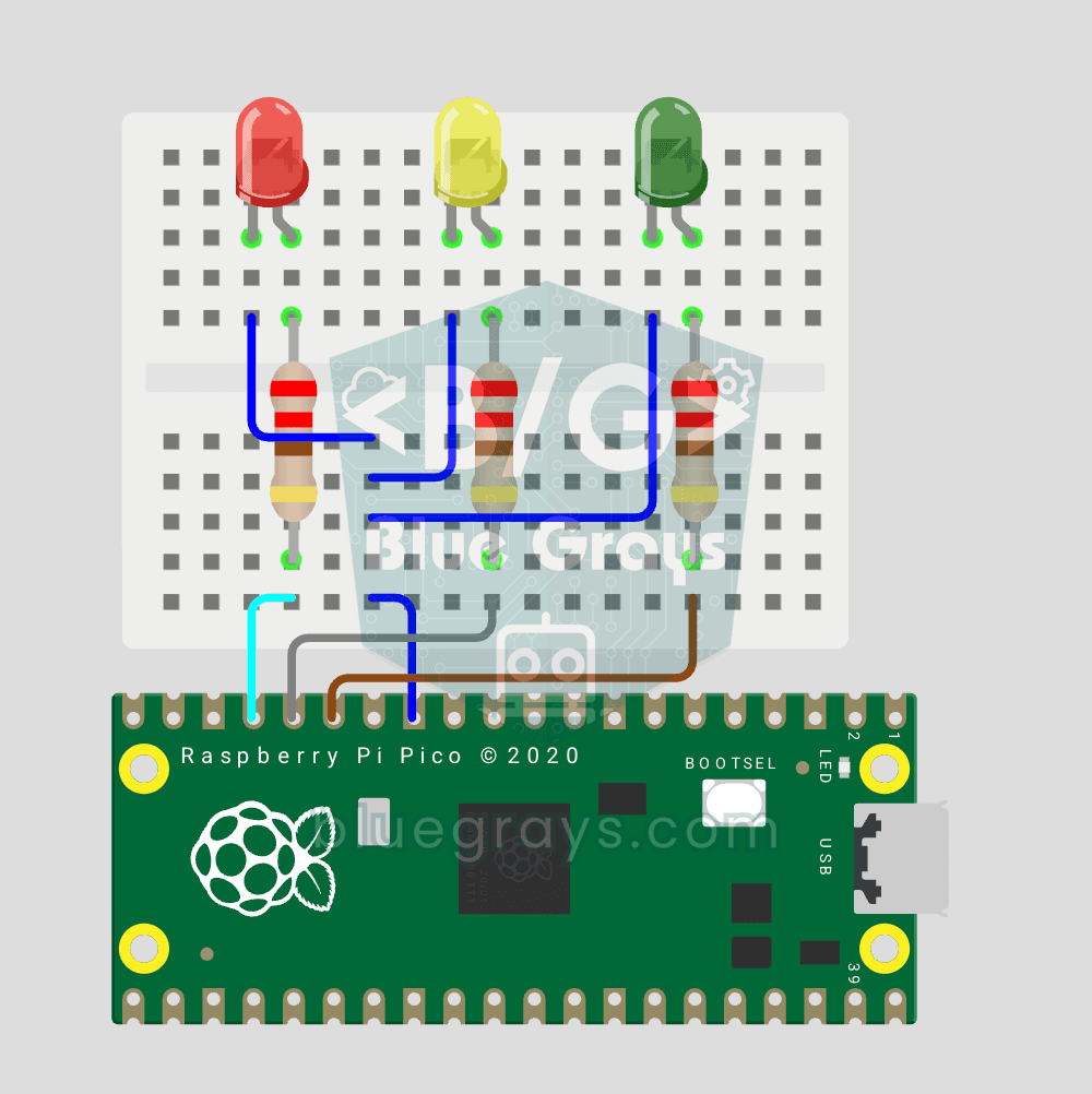
Raspberry Pi Pico Traffic Light Simulator (3 LEDs Sequential)
We simulate a real traffic light with red, yellow and green LEDs — the first 3-LED project of the Pico series! Green 4 sec "go", yellow 1.5 sec "ready", red 3 sec "stop" and red+yellow 1 sec "starting" (European traffic light pattern). Learn function definition (def all_off()), state machine logic (sequence) and multi-GPIO synchronization. Very simple circuit: 3 LEDs on GP11 (Green), GP12 (Yellow), GP13 (Red), each with a 220Ω current-limiting resistor. GP11-GP12-GP13 are ad