
ESP32 30 Pin vs 38 Pin: Pinout, Breadboard Fit, WROOM, CP2102
ESP32 30 pin vs 38 pin: side-by-side pinout, why it won't fit a breadboard, WROOM vs WROVER, CP2102 vs CH340 and which board to pick in the Arduino IDE.

The difference between an ESP32 30 pin vs 38 pin board is smaller than it looks: both usually carry the same ESP32-WROOM-32 module, run the same code and are set up as "ESP32 Dev Module" in the Arduino IDE. The 38-pin board breaks out eight extra pins: GPIO 0, GPIO 6–11 (wired to the flash memory) and one more GND. Since the flash pins can't be used anyway, the real difference usually comes down to GPIO 0, the order of the pins on the board and how it sits on a breadboard.
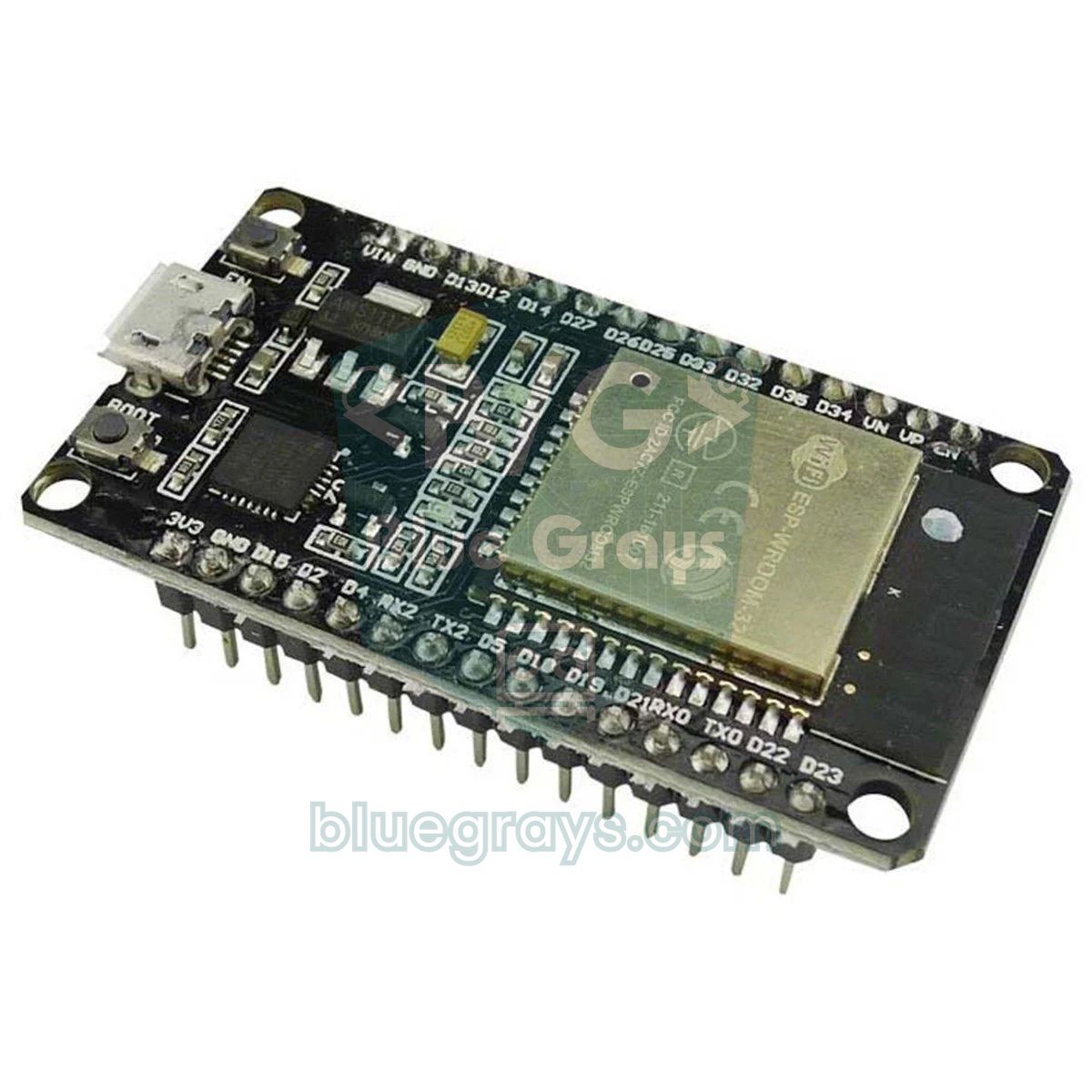
In this article we put the two pinouts side by side, explain why these boards don't fit a breadboard well and how to fix it, decode the WROOM and WROVER markings on the metal shield, show you how to tell whether your USB chip is a CP2102 or a CH340, and walk through the Arduino IDE settings step by step. At the end there's a test sketch that prints your board's chip model, flash size and PSRAM.
What's the difference between the ESP32 30-pin and 38-pin boards?
The ESP32-WROOM-32 module itself has 38 solder pads. The dev board maker decides which of them to route to the headers along the edges. Espressif's own ESP32-DevKitC and its clones offer 2×19 pins, one for every pad on the module. The DOIT ESP32 DevKit V1 and similar boards leave out the risky flash pins and GPIO 0 (the BOOT button pin) and make do with 2×15 = 30 pins. In other words, the 38-pin board isn't more powerful; it just breaks out more pads.
| Feature | 30-pin board (DevKit V1) | 38-pin board (DevKitC and clones) |
|---|---|---|
| Module | Usually ESP32-WROOM-32 / 32D / 32E | ESP32-WROOM-32 / 32E, some with WROVER |
| Header layout | 2 × 15 | 2 × 19 |
| GPIOs broken out | 25 | 32 (6 are flash pins) |
| GPIOs you can actually use | 25 | 26 |
| GPIO 0 | Not on a pin, only on the BOOT button | Available as a pin |
| Flash pins (GPIO 6–11) | No | Yes (CLK, SD0–SD3, CMD), not usable |
| GND pins | 2 | 3 |
| Power pins | VIN and 3V3 | 5V and 3V3 |
| User LED | Most have a blue LED on GPIO 2 | None on Espressif's board, GPIO 2 on some clones |
| Arduino IDE board | ESP32 Dev Module or DOIT ESP32 DEVKIT V1 | ESP32 Dev Module |
The takeaway from the table is simple: you'll never use six of the extra pins on the 38-pin board in any project, so the only real gain is GPIO 0. That's why "more pins means a better board" doesn't hold for the ESP32. Your choice should depend not on the pin count but on your breadboard layout, the wiring diagrams you'll follow and the expansion board you plan to use.
Pinout: where is each pin on the two boards?
The table below shows the pin order from top to bottom with the antenna at the top, the USB port at the bottom and the components facing you. DevKit V1 boards label pins like "D23" or "TX2"; remember that in your code you write the GPIO number (23, 17), not the label. You can also see your board's full map in the Pinout tool.
| Position | 30-pin left | 30-pin right | 38-pin left | 38-pin right |
|---|---|---|---|---|
| 1 | EN | D23 | 3V3 | GND |
| 2 | VP (GPIO 36) | D22 | EN | GPIO 23 |
| 3 | VN (GPIO 39) | TX0 (GPIO 1) | SVP (GPIO 36) | GPIO 22 |
| 4 | D34 | RX0 (GPIO 3) | SVN (GPIO 39) | TX (GPIO 1) |
| 5 | D35 | D21 | GPIO 34 | RX (GPIO 3) |
| 6 | D32 | D19 | GPIO 35 | GPIO 21 |
| 7 | D33 | D18 | GPIO 32 | GND |
| 8 | D25 | D5 | GPIO 33 | GPIO 19 |
| 9 | D26 | TX2 (GPIO 17) | GPIO 25 | GPIO 18 |
| 10 | D27 | RX2 (GPIO 16) | GPIO 26 | GPIO 5 |
| 11 | D14 | D4 | GPIO 27 | GPIO 17 |
| 12 | D12 | D2 | GPIO 14 | GPIO 16 |
| 13 | D13 | D15 | GPIO 12 | GPIO 4 |
| 14 | GND | GND | GND | GPIO 0 |
| 15 | VIN | 3V3 | GPIO 13 | GPIO 2 |
| 16 | - | - | SD2 (GPIO 9) | GPIO 15 |
| 17 | - | - | SD3 (GPIO 10) | SD1 (GPIO 8) |
| 18 | - | - | CMD (GPIO 11) | SD0 (GPIO 7) |
| 19 | - | - | 5V | CLK (GPIO 6) |
The left sides are very similar, but the right sides aren't: the 30-pin board has GND and 3V3 in its bottom-right corner, while the 38-pin board has GPIO 0, 2, 15 and the flash pins in the same area. So if you build a diagram drawn for one board by copying "the same position" on the other, you'll wire to the wrong pins. The order can vary slightly on clones; always go by the labels printed on your board.
The breadboard fit problem and how to solve it
A standard breadboard has five connected holes on each side of every row (a–e and f–j) with a channel in the middle. The ESP32 board straddles the channel and covers everything between its two headers. Boards with 22.86 mm (0.9 inch) between the pin rows leave one open hole on each side. Boards with 25.4 mm (1 inch) leave a single hole on one side only, and you can't plug a single wire into the pins on the other side. The width depends on the manufacturer; you'll find both widths among 30-pin and 38-pin boards, but the wide one is the most common. If you already have the board, measure the distance between the two rows of pins with a ruler; before buying, check the product dimensions.
- Two breadboards side by side: Remove the power rail strip from the edge of one, join the two breadboards and put one row of the board's pins in each. You get five holes next to every pin; it's the easiest and cheapest fix.
- Female-to-male jumper wires: Leave the board off the breadboard and connect directly to its pins with female-ended wires. It's quick for small tests, but the wires pop off easily.
- Expansion board (breakout base): These bases with screw terminals, or with GND and 3V3 next to every pin, take the breadboard out of the picture entirely. They're made separately for 30-pin and 38-pin boards, so buy the one that matches your board's pin count and width.
- Choose a narrow board: If you'll work on a breadboard a lot, choose a board with 22.86 mm between the pin rows. If the product page doesn't list that measurement, ask the seller.
WROOM vs WROVER: what does the metal shield tell you?
The label on the metal-shielded module shows the model name. WROOM modules contain just the processor and flash memory. WROVER modules are a little longer and also include external RAM called PSRAM. Models with a "U" (such as WROOM-32U or WROVER-IE) have no PCB antenna; instead they have a tiny U.FL connector for an external antenna. The D or E at the end of the name shows the version of the chip inside.
| Module | Chip | Flash | PSRAM | Note |
|---|---|---|---|---|
| ESP32-WROOM-32 | ESP32-D0WDQ6 | 4 MB | None | The first version; common on older, cheaper boards |
| ESP32-WROOM-32D | ESP32-D0WD | 4 MB (8 and 16 MB options exist) | None | The most common model for years |
| ESP32-WROOM-32E | ESP32-D0WD-V3 | 4, 8 or 16 MB | None | Newer boards; V3 silicon fixes bugs in the earlier chip |
| ESP32-WROOM-32U / 32UE | Same as WROOM-32D / 32E | 4 MB and up | None | U.FL connector for an external antenna |
| ESP32-WROVER-E / IE | ESP32-D0WD-V3 | 4, 8 or 16 MB | 2 or 8 MB | Longer module; GPIO 16 and 17 reserved for the PSRAM |
For almost every project, like reading sensors, driving a relay, running a web server or sending Telegram alerts, a WROOM is all you need; the ESP32's 520 KB of internal RAM is plenty for that. PSRAM makes a difference for memory-hungry jobs such as camera images, graphical interfaces on large color displays or audio recording. To use the PSRAM on a WROVER board you have to turn on PSRAM: Enabled in the Arduino IDE; if it's disabled, the memory doesn't show up at all.
USB-to-serial chip: CP2102 or CH340?
The ESP32 doesn't speak USB by itself; the small chip right next to the USB port translates between it and your computer. Which chip your board has decides what name it shows up under on your computer and which driver it needs. If the marking on the chip is too small to read, look at its shape:
| Chip | What it looks like | Name in Windows | USB ID (VID:PID) | Driver |
|---|---|---|---|---|
| CP2102 / CP2104 (Silicon Labs) | Square, no legs (QFN) | Silicon Labs CP210x USB to UART Bridge | 10C4:EA60 | Usually automatic; otherwise the CP210x VCP driver |
| CH340C / CH340G (WCH) | Rectangular, legs on both sides (SOP-16) | USB-SERIAL CH340 | 1A86:7523 | Usually automatic; otherwise the CH341SER driver |
| CH9102F (WCH) | Small square, no legs (QFN) | USB-Enhanced-SERIAL CH9102 | 1A86:55D4 | CH343SER driver on older systems |
On Windows, open Device Manager and look under Ports (COM & LPT); the entry that appears when you plug in the board tells you the chip. If it shows up as "Unknown device", right-click it, go to Properties > Details > Hardware Ids and compare the VID and PID with the table. Recent versions of macOS and Linux recognize most of these chips without extra drivers; the port appears as /dev/cu.usbserial-... on macOS and /dev/ttyUSB0 on Linux. On boards with a CH340G you'll see a small 12 MHz crystal next to the chip; the CH340C doesn't need one. For more on drivers and ports, see USB-to-TTL Converter.
Choosing the right board and settings in the Arduino IDE
- In the Boards Manager, search for esp32 and install the package by Espressif Systems. For a first-time setup, follow the steps in What Is the ESP32?.
- Under Tools > Board > esp32, choose ESP32 Dev Module. This option works with every 30-pin and 38-pin WROOM board.
- For the 30-pin board you can also choose DOIT ESP32 DEVKIT V1; the only difference is that it defines the LED_BUILTIN constant as GPIO 2.
- If your board has a WROVER, choose ESP32 Wrover Module, or set the PSRAM option to Enabled under ESP32 Dev Module.
- Pick your board's port under Tools > Port and upload. If the upload hangs at "Connecting...", hold down the BOOT button and release it once the upload starts.
| Tools menu setting | Recommended value | When to change it |
|---|---|---|
| Upload Speed | 921600 | 115200 if uploads stop halfway |
| CPU Frequency | 240MHz (WiFi/BT) | 80 or 160 MHz if you need to save battery |
| Flash Mode | QIO | DIO if a clone won't boot |
| Flash Size | 4MB (32Mb) | The real size on 8 or 16 MB modules |
| Partition Scheme | Default 4MB with spiffs | Huge APP (3MB No OTA) if your sketch doesn't fit |
| PSRAM | Disabled | Enabled on boards with a WROVER module |
A sketch that identifies your board: model, flash and PSRAM
Instead of guessing which chip, how much flash and how much PSRAM your board has, you can ask the board itself. Upload this sketch and open the Serial Monitor at 115200 baud:
1// Kartını tanı: yonga modeli, flaş, PSRAM ve MAC / Identify your board: chip model, flash, PSRAM and MAC
2void setup() {
3  Serial.begin(115200);
4  delay(1000);                                   // Seri Monitör'ün açılmasını bekle / wait for the Serial Monitor
5
6  Serial.printf("Yonga / Chip: %s, rev %d, %d cekirdek / cores\n",
7                ESP.getChipModel(), ESP.getChipRevision(), ESP.getChipCores());
8  Serial.printf("CPU: %lu MHz\n", (unsigned long)ESP.getCpuFreqMHz());
9  Serial.printf("Flas / Flash: %lu MB\n", (unsigned long)(ESP.getFlashChipSize() / (1024 * 1024)));
10  Serial.printf("PSRAM: %lu KB\n", (unsigned long)(ESP.getPsramSize() / 1024));   // WROOM: 0, WROVER: > 0 (PSRAM: Enabled)
11
12  uint64_t mac = ESP.getEfuseMac();              // fabrikada yazılan MAC / factory MAC
13  Serial.print("MAC: ");
14  for (int i = 0; i < 6; i++) {
15    Serial.printf("%02X", (unsigned int)((mac >> (8 * i)) & 0xFF));
16    if (i < 5) Serial.print(':');
17  }
18  Serial.println();
19}
20
21void loop() {
22}
If the output says ESP32-D0WDQ6, the module is most likely the original WROOM-32; ESP32-D0WD usually points to a WROOM-32D, and ESP32-D0WD-V3 (rev 3) to a WROOM-32E or WROVER-E. If the PSRAM line is greater than zero, your board is a WROVER, but that value only appears with the PSRAM option enabled. If the flash is larger than 4 MB, you can set Flash Size to the real value and make room for bigger programs. The MAC address helps you find your board in your router's list of connected devices.
Built-in LED and pin test
Most 30-pin DevKit V1 boards have a blue LED on GPIO 2, separate from the red power LED that stays on while the board is powered. Espressif's 38-pin DevKitC has no user LED, while some clones put one on GPIO 2 as well. The sketch below sets the safe output pins found on both boards HIGH one at a time for a second and prints which one is active to the Serial Monitor. Connect an LED to GND through a 220 Ω resistor and touch its other leg to the pins to check that the labels on your board are right.
1// 30 ve 38 pinli kartta ortak, güvenli çıkış pinleri / safe output pins found on both 30- and 38-pin boards
2const int LED_PIN = 2;   // DevKit V1 mavi LED; "ESP32 Dev Module" seçiliyken LED_BUILTIN tanımlı değildir
3                         // DevKit V1 blue LED; LED_BUILTIN is not defined when "ESP32 Dev Module" is selected
4const int pins[] = {4, 5, 13, 14, 16, 17, 18, 19, 21, 22, 23, 25, 26, 27, 32, 33};   // WROVER'da 16 ve 17'yi sil / remove 16 and 17 on WROVER
5const int count = sizeof(pins) / sizeof(pins[0]);
6
7void setup() {
8  Serial.begin(115200);
9  pinMode(LED_PIN, OUTPUT);
10  for (int i = 0; i < count; i++) pinMode(pins[i], OUTPUT);
11}
12
13void loop() {
14  for (int i = 0; i < count; i++) {
15    Serial.printf("GPIO %d -> HIGH\n", pins[i]);  // LED + 220 Ω ile bu pini yokla / probe this pin with an LED + 220 Ω
16    digitalWrite(LED_PIN, HIGH);                  // dahili LED test sırasında yanar / onboard LED lights during the test
17    digitalWrite(pins[i], HIGH);
18    delay(1000);
19    digitalWrite(pins[i], LOW);
20    digitalWrite(LED_PIN, LOW);
21    delay(200);
22  }
23}
Which pins are safe? Same rules on both boards
| Pin | Status | Why? |
|---|---|---|
| GPIO 6–11 | Don't use | Wired to the flash; only broken out on the 38-pin board |
| GPIO 0 | Use with care | Connected to the BOOT button; if it's LOW at boot, the board enters upload mode |
| GPIO 2 | Use with care | Must be LOW or floating during upload; drives the built-in LED on the DevKit V1 |
| GPIO 12 | Use with care | If it's HIGH at boot, 1.8 V is selected for the flash and the board won't start |
| GPIO 15 | Use with care | If it's LOW at boot, the boot messages are silenced |
| GPIO 1 and 3 | Use with care | TX0 and RX0 of the USB serial connection |
| GPIO 34, 35, 36, 39 | Input only | Can't be outputs and have no internal pull-up |
| GPIO 16 and 17 | Don't use on WROVER | Wired to the PSRAM on WROVER; available on WROOM (TX2 and RX2) |
| GPIO 4, 5, 13, 14, 18, 19, 21–23, 25–27, 32, 33 | Safe | General-purpose input and output |
Power pins: VIN, 5V and 3V3
The VIN pin on the 30-pin board and the 5V pin on the 38-pin board do the same job: they're tied to the USB 5 V line and feed the board's 3.3 V regulator (usually an AMS1117). To run the board without USB, you supply 5 V through this pin; the regulator needs at least about 4.5 V and gets very hot at higher voltages, so 5–6 V is the safest range. The 3V3 pin is the regulator's output, and you can power your sensors from it. Because the ESP32 draws peaks of up to 250 mA when Wi-Fi switches on, don't draw more than a few hundred mA from 3V3. Powering VIN while the USB cable is plugged in can also tie two supplies together; pick one.
If you use MicroPython
The 30-pin and 38-pin boards run the same MicroPython firmware: just flash Espressif's generic ESP32 build, or the PSRAM-enabled (SPIRAM) build for WROVER boards. In the Thonny shell, these few lines show the flash size and CPU speed, and turn on the DevKit V1's LED:
1import esp, machine
2
3print("Flas / Flash:", esp.flash_size() // (1024 * 1024), "MB")
4print("CPU:", machine.freq() // 1000000, "MHz")
5
6led = machine.Pin(2, machine.Pin.OUT)    # DevKit V1 dahili LED / onboard LED
7led.on()
Which one should you buy? A quick decision guide
- For breadboard practice or teaching: get a 30-pin DevKit V1, ideally a narrow one with 22.86 mm between the pin rows; its built-in LED is handy for first tests too.
- If the diagram or book you're following uses a specific board: buy that same board; since the pin positions differ, you won't have to translate them.
- If you need GPIO 0 or your expansion board is a 38-pin one: choose the 38-pin board.
- For camera, large display or audio projects: consider a board with a WROVER module, or go straight for an ESP32-CAM.
- If you don't want driver headaches: pick a newer board with a CP2102 or CH340C and a USB-C port.
- ESP32-S3, C3 or C6 boards: these are different chips; their pin numbers and layouts aren't compatible with the boards in this article.
Common mistakes and how to fix them
- "LED_BUILTIN was not declared" error: this constant isn't defined when ESP32 Dev Module is selected. Write 2 instead of LED_BUILTIN, or choose DOIT ESP32 DEVKIT V1 as your board.
- I wired it to the pin in the diagram and it doesn't work: the diagram may have been drawn for the other layout. Wire by the printed label and GPIO number, not by position.
- The board won't boot or keeps rebooting: something may be connected to GPIO 6–11, or GPIO 12 is pulled HIGH at boot. Remove whatever is on those pins and try again.
- The port doesn't show up: the cable may be charge-only, or the USB chip's driver is missing. Use a data cable and compare the name in Device Manager with the table.
- "Failed to connect" error: hold BOOT as the upload starts; if it keeps happening, lower Upload Speed to 115200. More fixes are in ESP32 Failed to Connect.
- PSRAM shows 0 on a WROVER board: the PSRAM option was left Disabled in the Tools menu; set it to Enabled and upload again.
In short, 30-pin and 38-pin ESP32 boards share the same brain; what sets them apart is where the pins are, GPIO 0 and how the board fits on your workbench. Once you've read your board's labels and confirmed them with the test sketch, you'll find the right pins whatever diagram you follow. For your first experiments, check out the ESP32 projects in the BlueGrays app for the built-in LED, an external LED, button-controlled LEDs, a traffic light, light measurement with an LDR, an I2C LCD and a Wi-Fi connection; each one walks you through the wiring diagram and the code step by step.
Frequently asked questions
Should I buy the 30-pin or the 38-pin ESP32?
If you'll be working on a breadboard and don't have a special need, the 30-pin DevKit V1 is usually more convenient and most have a built-in LED. Choose the 38-pin board if you want to use GPIO 0, have a 38-pin expansion board, or the diagram you're following was drawn for it. The processor and the code are the same on both.
Do I need to change my code for a 30-pin ESP32?
No. As long as the code uses GPIO numbers, it runs the same way on 30-pin and 38-pin boards. Just check that code written for a 38-pin board doesn't use GPIO 0 or the flash pins, because those pins aren't broken out on the 30-pin board.
What pin is the built-in LED on the ESP32 DevKit V1?
On DevKit V1 boards the blue user LED is on GPIO 2. With ESP32 Dev Module selected in the Arduino IDE, LED_BUILTIN isn't defined, so write 2 directly in your code or choose the DOIT ESP32 DEVKIT V1 board. The red LED is just a power indicator and can't be controlled.
Which board do I select in the Arduino IDE for a 38-pin ESP32?
For every board with a WROOM module, whether 30 or 38 pins, ESP32 Dev Module is all you need. If your 38-pin board has a WROVER module, select ESP32 Wrover Module or enable the PSRAM option under ESP32 Dev Module.
What is the difference between ESP32 WROOM and WROVER?
Both contain the same ESP32 chip. The WROVER adds 2 to 8 MB of PSRAM and is slightly longer, but GPIO 16 and 17 are reserved for that memory in exchange. Unless you're working on camera, large display or audio projects, a WROOM is enough.
How do I know if my ESP32 has a CP2102 or a CH340?
Look at the small chip next to the USB port: a square one with no legs is usually a CP2102, while a rectangular one with legs on both sides is a CH340. In Windows Device Manager the board shows up as "Silicon Labs CP210x" or "USB-SERIAL CH340"; in the hardware ID, 10C4 means Silicon Labs and 1A86 means WCH.
Projects to build after reading this
See all projects
ESP32 Built-in LED Blink
Blinking the built-in blue LED on the ESP32 DevKit V1. No external components required! The first project you should try when you buy an ESP32. GPIO 2 is connected to the built-in LED.

LED Blink with ESP32
Teaches basic GPIO output usage with ESP32. We achieve a blinking effect by turning an LED on and off from a digital pin. ESP32 version of the classic blink project on Arduino UNO; the basic blink commands in the Arduino environment are the same, but the ESP32's pin layout and 3.3 V GPIO levels differ from those of the Arduino UNO.

ESP32 LED Control with Push Button (Push)
The LED lights up when the button is pressed and turns off when released. Shows how the ESP32's digital input pin and internal pull-up resistor are used. The INPUT_PULLUP mode eliminates the need for an external resistor.

ESP32 LED Control with Pushbutton (Toggle)
Each time the button is pressed the state of the LED changes: if it is on it turns off, if it is off it turns on. Classic toggle pattern. With debounce we clean up the mechanical noise of the pushbutton to ensure a single toggle with a single press.

ESP32 Traffic Light
Real traffic light simulation with 3 LEDs red-yellow-green. Timings close to real traffic logic: red long, yellow short, green long. Classic example of sequential GPIO control.

Reading Light Intensity with the ESP32 LDR Module
Real-time monitoring of the LDR module's raw ADC value and relative light percentage calculated from dark and light reference values in the Serial Monitor. This percentage is not a lux measurement. Teaches the module’s calibration logic. It is ideal to complete this before Project 10, as it is used to determine the threshold value.

ESP32 I2C LCD Display (16x2)
In this project we connect a 16x2 character LCD to the ESP32 over I2C and display text. With I2C, just 2 data pins (SDA and SCL) control the screen, instead of the 6+ pins a classic parallel connection wastes. The code prints a fixed message on the first line and a counter that goes up every second on the second. At startup an I2C scanner also prints the display's address to the Serial Monitor (usually 0x27 or 0x3F).

ESP32 Wi-Fi STA Connection (with LCD Screen)
In this project, we connect the ESP32 to the home Wi-Fi network in Station (STA) mode in a secure, fault-tolerant manner. We store the SSID and password in a separate secrets.h file to prevent leaking to Git, set up an auto-reconnect mechanism, and display the RSSI signal level and IP address on an I2C LCD screen. The internal LED works as a status indicator. It is a production-grade connection manager.