
How to Use a Breadboard: Power Rails and Your First LED Circuit
How do you use a breadboard? Power rails, 5-hole columns and the centre channel, your first LED circuit with a resistor, ESP32 and Pico placement, wiring habits.

The short answer to how to use a breadboard: under its plastic body, metal strips connect certain holes to each other. You build circuits without soldering by plugging legs that must connect into the same strip and legs that must not into different strips. Each numbered column's group of five holes (a–e and f–j) is connected internally, the centre channel splits the board into two independent halves, and the long power rails along the edges carry + and − supply from one end of the board to the other. Once you grasp these three rules, every experiment with Arduino, ESP32 or Raspberry Pi Pico goes faster and with fewer mistakes.
In this guide we'll look at the breadboard's internals hole by hole, light an LED first without any code, then make the same circuit blink with an Arduino. After that you'll see how to place the ESP32, which causes trouble with its wide body, and the Raspberry Pi Pico, which fits a breadboard almost perfectly, how to keep jumper wires tidy, and the small mistakes that eat beginners' hours.
What is a breadboard and how does it work?
A breadboard is a reusable experimenting platform, also called a solderless board or prototyping board. Under every hole there's a spring metal clip; when you push a resistor leg or a jumper wire end into the hole, the clip grips the wire from both sides and makes electrical contact. The hole spacing is 2.54 mm (0.1 inch), so ICs, pin headers, buttons and most modules fit directly. The clips comfortably hold solid-core wire of 20–29 AWG (about 0.3–0.8 mm diameter); the ideal wire is 22 AWG solid-core.
| Type | Total holes | Power rail | Best for |
|---|---|---|---|
| Mini breadboard | 170 (17 columns × 10) | None | A single sensor, small module tests |
| Half-size | 400 (300 + 100 rail) | 2 pairs, 25 holes each | Beginner projects, Pico and Nano |
| Full-size | 830 (630 + 200 rail) | 2 pairs, 50 holes each | Projects with many components, ESP32 |
| Joinable sets | Depends on module | Detachable rails | Large prototypes, using two boards side by side |
Inside the breadboard: power rails, columns and the centre channel
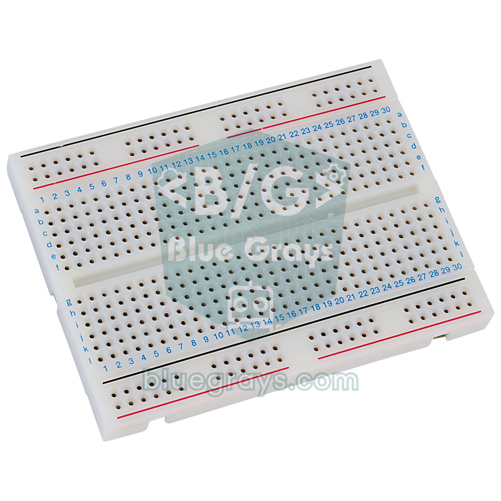
Place the breadboard with its long edge horizontal. The numbers 1, 2, 3 along the edge mark the columns, and the letters a to j mark the rows. The a, b, c, d, e holes in the same numbered column are connected underneath by a single metal strip; the f, g, h, i, j holes of that column are connected by a separate strip. So a leg in 12a is at the same point as a leg in 12c, but has no connection with 13a or 12f. If you plug both legs of a component into the same group of five, you short-circuit it; the current flows through the metal strip, not through the component.
The wide gap between e and f is called the centre channel, and it is exactly 7.62 mm (0.3 inch) wide. This size is deliberate: DIP-package ICs (such as the 555, 74HC595 and L293D) sit across this channel like a bridge, so each pin lands in its own group of five and opposite pins don't touch. Boards like the Arduino Nano and Raspberry Pi Pico are placed across the channel on the same principle. Because the channel keeps the two halves independent, it's also a tidy way to connect buttons and two-legged components across it.
The long lines along the top and bottom edges are the power rails. The rail with the red line is usually used for + (5 V or 3.3 V) and the rail with the blue or black line for − (GND). Unlike the columns, these rails are connected horizontally along the length of the board. So when you run the Arduino's 5V and GND pins to the rails with one wire each, you can carry power to any component on the board with a short wire. The top and bottom rails aren't connected to each other; if you want power on both sides, you need to join the rails with a wire at one end each.
| Area | How is it connected? | What is it used for? |
|---|---|---|
| Holes a–e (each column) | The 5 holes in the same column are connected | Joining component legs |
| Holes f–j (each column) | The 5 holes in the same column are connected, not connected to a–e | The other half of the channel |
| Centre channel | No connection, separates the two halves | ICs, Nano, Pico, buttons |
| Power rail (+) | Connected horizontally along the board | Distributing 5 V or 3.3 V supply |
| Power rail (−) | Connected horizontally along the board | Distributing GND (ground) |
First LED circuit: step by step, no code
In the first experiment we'll use the microcontroller only as a power supply; that way, if something goes wrong, you'll know the problem is the wiring, not the code. What you need: an Arduino Uno, a red LED, a 220 Ω resistor (red-red-brown bands) and three jumper wires.
- Work with the Arduino's USB cable unplugged. First connect the Arduino's GND pin to the breadboard's blue (−) rail and its 5V pin to the red (+) rail.
- Plug one leg of the 220 Ω resistor into the + rail and the other leg into, for example, hole 10a.
- Plug the LED's long leg (anode) into hole 10e; this puts it in the same column as the resistor, so at the same point.
- Plug the LED's short leg (cathode) into hole 11e. The two legs must be in different columns, otherwise the LED is short-circuited.
- Run a short wire from hole 11a to the blue (−) rail. The circuit is now complete: + rail, resistor, LED, − rail.
- Plug in the USB cable. If the LED lights up, the circuit is right; if not, flip the LED around and try again.
You can calculate the current through the LED in this circuit with Ohm's law: a red LED drops about 2 V, the remaining 3 V falls across the resistor, and the current is I = 3 V / 220 Ω ≈ 13.6 mA. This value is safe for the LED and bright enough. If you use a different colour or supply voltage, you can find the right value with the LED resistor calculator, and if you're not sure of your resistor's value, you can decode the bands with the resistor colour code tool. For a detailed explanation, see calculating LED resistors.
Blinking the LED with Arduino
Now that the circuit works, remove the resistor leg that goes to the + rail and connect it, via a wire, to the same column as an Arduino digital pin. The table below shows the connections used in all the experiments in this article for three boards together; the button row is for the second experiment in the ESP32 and Pico section. If you have trouble finding the pins on your board, you can use the pinout tool.
| Connection | Arduino Uno | ESP32 | Raspberry Pi Pico |
|---|---|---|---|
| LED signal (through 220 Ω) | D8 | GPIO 18 | GP14 (physical pin 19) |
| Button (other leg to GND) | D2 | GPIO 4 | GP15 (physical pin 20) |
| + power rail | 5V | 3V3 | 3V3(OUT) (physical pin 36) |
| − power rail | GND | GND | GND (physical pin 18 or 38) |
1const int LED_PIN = 8;          // LED'in bağlı olduğu pin / pin the LED is connected to
2
3void setup() {
4  pinMode(LED_PIN, OUTPUT);      // pini çıkış yap / set the pin as output
5}
6
7void loop() {
8  digitalWrite(LED_PIN, HIGH);   // LED'i yak / turn the LED on
9  delay(500);                    // 0,5 saniye bekle / wait 0.5 s
10  digitalWrite(LED_PIN, LOW);    // LED'i söndür / turn the LED off
11  delay(500);
12}
The code is very short but ideal for testing the breadboard side: pinMode makes D8 an output, digitalWrite pulls the pin to 5 V (HIGH) or 0 V (LOW), and delay waits half a second. If the LED blinks once per second, you know both the wiring and the code upload are correct. The Arduino Uno doesn't sit on the breadboard; it's connected to the board with jumper wires from its pins. The Arduino Nano, on the other hand, sits across the centre channel just like an IC and leaves three free holes next to each pin.
Seating the ESP32 on a breadboard
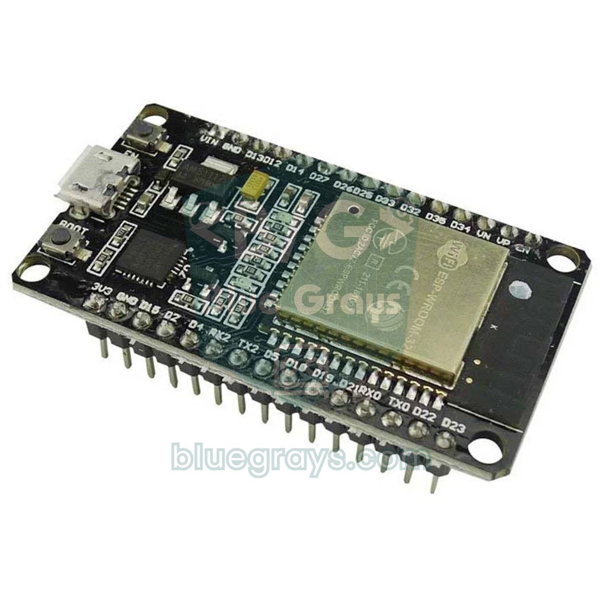
ESP32 DevKit boards (30- and 38-pin versions) are noticeably wider than an Arduino Nano. When you seat one across a standard breadboard's centre channel, the two pin rows cover almost the whole board: at most one or two free holes are left next to each pin, and on some models one side is completely blocked. That leaves you nowhere to plug in wires. Decide which pins you'll use before inserting the board and make sure the pins are straight. When removing it, don't lift one end; pull evenly from both sides, rocking it slightly, so the pins don't bend. To get to know the board itself, see What is the ESP32.
- Two breadboards side by side: The side rail of most breadboards is a snap-on type that slides off. Remove the rail between them to join the two boards and seat the ESP32 across the middle like a bridge; plenty of holes remain on both sides.
- Keep the pins you use exposed: If your project only uses the pins on one row, slide the board so that two free holes are left next to that row.
- Male-to-female jumpers: You can keep the ESP32 off the breadboard and bring only the pins you need to the board with female-ended wires.
- The 3.3 V rule: Connect the ESP32's 3V3 pin to the + rail. If you also use 5 V on the same board, put the two voltages on separate rails and never feed 5 V into a GPIO pin.
Now let's build the second experiment: this time we'll light the LED with a button. Place the four-legged button across the centre channel. One leg goes to GPIO 4's column and the diagonally opposite leg goes to the − rail. The LED connects from GPIO 18 through a 220 Ω resistor. At 3.3 V, about (3.3 − 2) / 220 ≈ 6 mA flows through a red LED; that's enough for a clearly visible brightness. We don't use an external resistor on the button because we turn on the ESP32's internal pull-up resistor.
1const int LED_PIN = 18;      // LED + 220 ohm / LED + 220 ohm
2const int BUTTON_PIN = 4;    // buton, diğer bacağı GND / button, other leg to GND
3
4void setup() {
5  pinMode(LED_PIN, OUTPUT);
6  pinMode(BUTTON_PIN, INPUT_PULLUP);   // dahili pull-up açık / internal pull-up on
7}
8
9void loop() {
10  bool pressed = (digitalRead(BUTTON_PIN) == LOW);   // basılıyken LOW okunur / reads LOW while pressed
11  digitalWrite(LED_PIN, pressed ? HIGH : LOW);
12  delay(10);                                          // kısa bekleme / short pause
13}
Seating the Raspberry Pi Pico on a breadboard
The Raspberry Pi Pico is practically designed to measure for a breadboard. The distance between its two pin rows is 17.78 mm (0.7 inch), so if you seat it across the channel with the pins landing in rows c and h, two free holes remain next to each pin, a–b and i–j. The Pico usually comes without pin headers soldered; unless you bought the Pico H version with headers, you'll need to solder the 2 × 20 male pin headers yourself. Because the pin numbers are printed on the underside of the board, not the top, they're hard to read once it's placed; knowing that physical pin 1 is on the USB side, in the top-left corner, makes it easier. To get to know the board, see What is the Raspberry Pi Pico.
Let's build the same button and LED experiment on the Pico with MicroPython. The LED goes from GP14 (physical pin 19) through a 220 Ω resistor to the − rail; since physical pin 18 right next to it is already GND, connecting the − rail is very easy. The button connects to GP15 (physical pin 20), and its diagonal leg again goes to the − rail.
1from machine import Pin
2import time
3
4led = Pin(14, Pin.OUT)                 # GP14 (fiziksel pin 19) / GP14 (physical pin 19)
5buton = Pin(15, Pin.IN, Pin.PULL_UP)   # GP15 (fiziksel pin 20), dahili pull-up / internal pull-up
6
7while True:
8    if buton.value() == 0:             # basılıyken 0 okunur / reads 0 while pressed
9        led.value(1)
10    else:
11        led.value(0)
12    time.sleep_ms(10)                  # kısa bekleme / short pause
Jumper wire layout: building a readable circuit
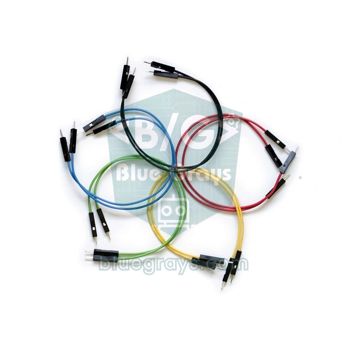
As a circuit grows, the real difficulty isn't the components but the wires. Long, randomly coloured wires that cross over each other make it impossible to find errors and cause another connection to pop out when you pull one wire. The habits below look small, but they seriously shorten your debugging time.
- Set a colour rule and stick to it: Red is always +, black or blue is always GND. Use other colours such as yellow, green and orange for signals.
- Short, flat wires: For connections within the breadboard, use cut-and-bent jumper kits that lie flat against the board instead of long flexible wires.
- Trim the legs: If you shorten the legs of resistors and LEDs you'll use permanently, components don't dangle in the air or touch their neighbours.
- Use the right wire type: Male-to-male wires go between the breadboard and Arduino, male-to-female wires on module pins, and female-to-female wires to join two modules' pins directly.
- Split into zones: Group inputs (button, sensor) on one side of the board and outputs (LED, buzzer) on the other; put the microcontroller at one end.
- Don't plug stranded wire in directly: Fine wires with frayed ends break off inside the holes and ruin the clips; always use pinned wire or solid-core wire.
- Take a photo: Before taking apart a working circuit, take a photo of it from above; it's the fastest guide when you want to rebuild the same circuit.
First project ideas with a breadboard
- Traffic light: Reinforce the column logic with three LEDs and three resistors; the steps are in the Arduino traffic light article.
- Running LEDs: Line up six LEDs in adjacent columns and make Knight Rider and chaser LED effects.
- Button on/off: Go deeper into connecting a button across the channel and debounce logic with how to connect a button.
- Brightness control: Change the LED brightness with a potentiometer; learn to plug a three-legged component into three separate columns.
- Night light: Build a voltage divider with an LDR light sensor and a resistor to switch the LED on automatically in the dark.
- External power: If you'll use motors or many LEDs, feed 5 V and 3.3 V to the rails with an MB102 breadboard power module.
Common mistakes and how to fix them
| Symptom | Likely cause | Fix |
|---|---|---|
| The LED doesn't light at all | LED is in backwards, or the resistor and LED leg aren't in the same column | Long leg to the + side; plug the legs where the resistor and LED meet into the same group of 5 |
| Half of the board doesn't work | The power rail is split in the middle | Join the two halves of the rail with a short jumper wire |
| The resistor gets hot, the LED is too bright or burns out | Both resistor legs are in the same column, so the resistor is bypassed | Plug the resistor legs into different columns |
| The button acts as if it's always pressed | The two internally connected legs of the button were used | Place the button across the channel and use the diagonal legs |
| A sensor or module gives nonsense values | No common GND on an external supply | Join the supply's GND with the board's GND |
| The circuit keeps working only when touched | Loose clip, thin leg or worn-out hole | Move the component to another area, use 22 AWG solid-core wire |
| The ESP32 or Pico gets hot, a pin is damaged | The 5 V rail was connected to a 3.3 V pin | Label the rails, use only 3V3 on 3.3 V boards |
| Wires and clips get hot | A high-current load such as a motor is powered through the breadboard | Supply high current with separate wires, through a driver module |
When you start using an external power supply, adapter or battery, the most often overlooked topic is common ground. For a microcontroller to read a signal as 'high' or 'low', the two circuits must share the same GND reference; you'll find examples of why this matters in GND and common ground. Also remember this: clips in areas that are plugged and unplugged often loosen over time. If you keep having trouble in the same holes, moving the component a few columns over often solves the problem right away.
Once the breadboard's logic clicks, every new sensor and module is only a few wires away. When your circuit has made it through testing and finally works the way you want, you can make it permanent on perfboard. In the BlueGrays app you can follow LED blinking, traffic light, button LED control and the first ESP32 and Pico projects step by step, with circuit diagrams showing the breadboard layout and ready-made code.
Frequently asked questions
Which breadboard holes are connected to each other?
In each numbered column, the five holes a–e are connected to each other, and the five holes f–j are connected to each other. The centre channel separates these two groups. The + and − power rails along the edges are connected horizontally along the length of the board.
Why is my breadboard power rail not working?
On most full-size breadboards the power rails are split in two in the middle, and the two halves aren't connected. If there's a gap in the middle of the red or blue line, the rail is split. Joining the two halves with a short jumper wire fixes the problem; to be sure, you can use your multimeter's continuity mode.
How much current can a breadboard carry?
Breadboard clips are generally considered safe up to around 1 A, and the voltage should also be low (usually below 5 V or 12 V). That's more than enough for LED, sensor and microcontroller circuits. Motors, long LED strips and 220 V mains voltage must not be run through a breadboard.
Why doesn't the ESP32 fit on a breadboard?
ESP32 DevKit boards are wide, so on a standard breadboard at most one or two holes are left next to the pins, and sometimes one side is completely blocked. As a fix, you can remove the rail between two breadboards, join them side by side and seat the ESP32 in the middle. Alternatively, you can keep the board off the breadboard and connect it with male-to-female jumper wires.
Which way should I put an LED in a breadboard?
The LED's long leg is the anode (+), the short leg is the cathode (−), and the edge of the body is flat on the cathode side. The long leg goes in the same column as the resistor, and the short leg in the column that leads to the GND rail. Make sure the two legs aren't in the same group of 5, otherwise the LED is short-circuited and won't light.
Should I buy a 400-hole or an 830-hole breadboard?
A 400-hole half-size breadboard is enough for beginner projects with one sensor and a few LEDs, and for the Arduino Nano and Raspberry Pi Pico. If you'll use an ESP32 or connect several modules at once, an 830-hole full-size breadboard is more comfortable. Joining two half-size boards is also a flexible option.
Projects to build after reading this
See all projects
LED Blink
The very first hello of electronics: switching a single LED on and off. The Arduino turns the LED on and off at short intervals, so the light blinks quickly.

Two LEDs Blinking Alternately
Two LEDs blink quickly in turn: when one lights up the other goes off, as if they were tossing a ball back and forth.

Traffic Light
A tiny copy of the traffic light you see on the road every day. Red stays on for two seconds, yellow flashes for a moment, green stays on for two seconds, then it goes back to red through yellow…

LED Control with a Push Button (Push)
Just like a doorbell: the light stays on as long as you press, and goes off when you let go.

LED Blink with ESP32
Teaches basic GPIO output usage with ESP32. We achieve a blinking effect by turning an LED on and off from a digital pin. ESP32 version of the classic blink project on Arduino UNO; the basic blink commands in the Arduino environment are the same, but the ESP32's pin layout and 3.3 V GPIO levels differ from those of the Arduino UNO.

ESP32 LED Control with Push Button (Push)
The LED lights up when the button is pressed and turns off when released. Shows how the ESP32's digital input pin and internal pull-up resistor are used. The INPUT_PULLUP mode eliminates the need for an external resistor.
Raspberry Pi Pico: Controlling an External LED (Breadboard)
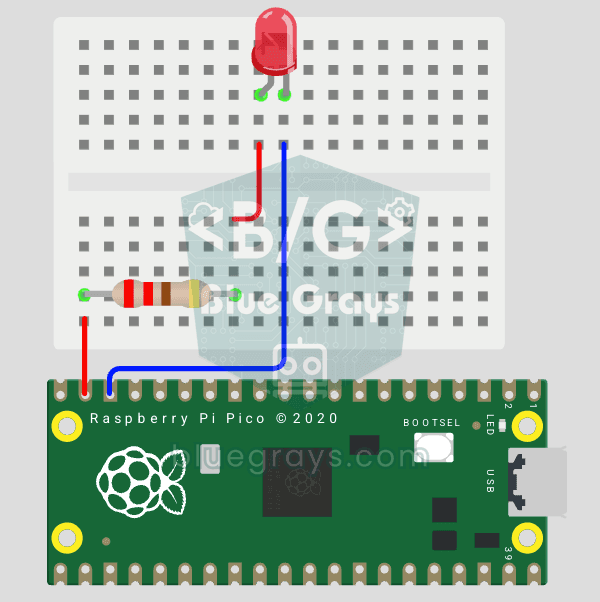
The next step after the Pico's built-in LED: connect an external LED on a breadboard and control it through pin GP14. You'll learn how to use any of the Pico's GPIO pins as an output, the LED's polarity (long leg = anode/+, short leg = cathode/–) and why a current-limiting resistor (220Ω) is a must. Without the resistor, too much current flows through the LED and it can burn out.
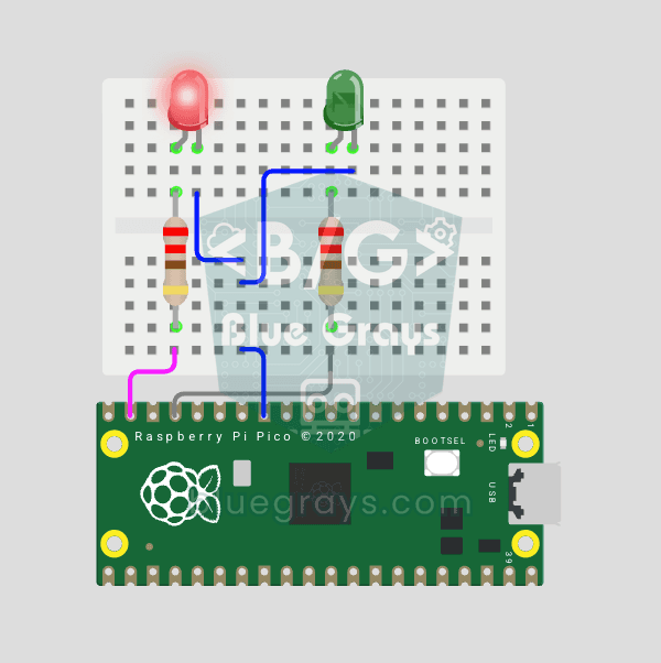
Raspberry Pi Pico Alternating Two LEDs (Blink-Flip Pattern)
The next step after the Pico's single LED: the classic flip-flop animation, with two LEDs blinking in turn. One LED turns off as the other turns on, the most basic example of handling multiple GPIOs. Two LEDs of different colors (red on GP14, green on GP13) swap every 500 ms. With MicroPython's Pin.toggle() method, the code stays short and readable.