
USB to TTL Serial Adapter: Using the CH340 and CP2102
What does a USB to TTL adapter do? TX-RX crossover, the 3.3 V/5 V jumper, drivers, programming Pro Mini, ESP-01 and ESP32-CAM, and CH340 vs CP2102 compared.
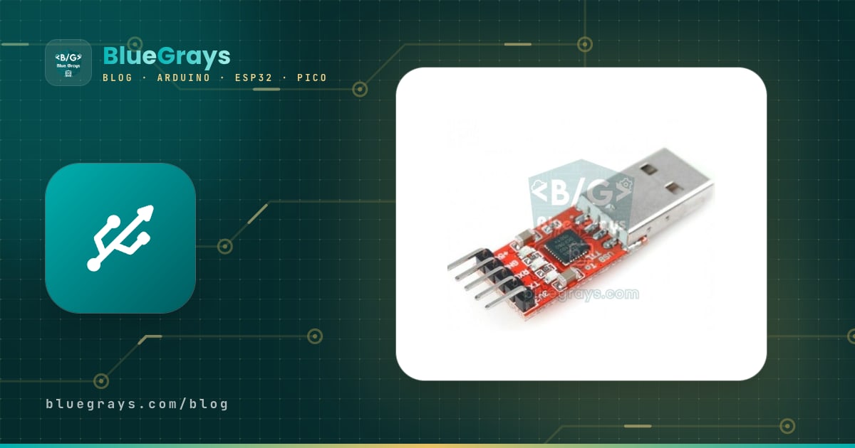
A USB to TTL adapter is a small board that translates your computer's USB port into the serial (UART) language that microcontrollers speak. You need one to upload code to boards with no USB socket, such as the Arduino Pro Mini, ESP-01 and ESP32-CAM, to read the serial messages coming out of a module, or to configure GPS and Bluetooth modules straight from your computer. In fact every Arduino Uno and Nano already carries a copy of this circuit; the adapter turns it into a separate, portable module.
In this guide you'll learn the adapter's pins, the most common mistake of all (TX-RX wiring), the jumper that selects 3.3 V or 5 V logic level, and driver installation on Windows, macOS and Linux. Then you'll see how to program an Arduino Pro Mini without pressing a button thanks to the DTR pin, upload code to the ESP-01 and ESP32-CAM, use the adapter as a second serial monitor, and how the three most common chips, the CH340, CP2102 and FT232, differ.
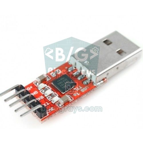
What is a USB to TTL adapter and what is it for?
Your computer and a microcontroller speak different languages. USB is a complex protocol built on packets, addresses and drivers. A microcontroller's UART, on the other hand, uses just two lines: one sends data (TX), the other receives it (RX), and each byte is made of bits sent one after another at an agreed speed (baud). The chip on the adapter shows up on your computer as a virtual serial port (COM3 on Windows, /dev/cu.usbserial... on macOS, /dev/ttyUSB0 on Linux); every byte you write to that port leaves the TX pin as a UART signal, and every byte arriving on the RX pin is passed to the computer. The TTL in its name means the signals swing between 0 V and 5 V, or 0 V and 3.3 V.
- Programming boards without USB: Arduino Pro Mini, LilyPad, ESP-01, ESP32-CAM and bare ATmega328P chips with a bootloader.
- Reading serial logs: Watching debug messages in a second window while the board's own USB is busy with something else.
- Talking to modules directly: Sending AT commands to an ESP-01, reading a GPS module's NMEA sentences, renaming a Bluetooth module.
- Rescuing a damaged board: Programming an Uno or Nano whose USB chip has died through its D0 and D1 pins.
- Connecting to other devices' consoles: The serial console pins of routers, 3D printer boards or single-board computers.
USB to TTL pins: GND, VCC, TXD, RXD, DTR and RTS
| Pin | Function | Note |
|---|---|---|
| GND | Common ground | Always connected |
| 5V | 5 V output from USB | Usually up to 500 mA, depending on the computer's port |
| 3V3 | 3.3 V output | From the chip or a small regulator; limited current |
| TXD | Data output (computer to board) | Goes to the target board's RX pin |
| RXD | Data input (board to computer) | Goes to the target board's TX pin |
| DTR | Control line that goes LOW when the port opens | Used for auto-reset on Arduinos |
| RTS / CTS | Flow control lines | RTS is used in the auto-upload circuit of ESP boards; CTS is left unconnected in most projects |
TX-RX crossover wiring
The most common mistake is connecting TX to TX. The rule is simple: the line one device talks on must go to the line the other one listens on. So the adapter's TXD pin goes to the target board's RX pin, and its RXD pin goes to the target's TX pin. Some boards add the direction to their labels to avoid confusion: the Arduino Pro Mini says RXI (RX in) and TXO (TX out), and SparkFun-style FTDI boards are labelled so that plugging the two boards straight together produces the correct crossover. If you can't trust the labels, try the wiring the other way round once; swapping TX and RX doesn't damage anything, there's just no communication.
| Adapter | Target board | Description |
|---|---|---|
| GND | GND | Common ground, a must |
| TXD | RX (RXI, U0R) | Crossed: transmitter to receiver |
| RXD | TX (TXO, U0T) | Crossed: receiver to transmitter |
| 5V or 3V3 | VCC | Only if the target board has no other power supply |
| DTR | DTR / GRN / RST | Only if you need auto-reset |
The 3.3 V / 5 V jumper: how to choose the logic level
The Arduino Uno, Nano and the 5 V Pro Mini use 5 V logic; the ESP8266, ESP32 and Raspberry Pi Pico use 3.3 V logic. Feeding a 5 V signal into an ESP's RX pin stresses its input protection diodes and can wear out the pin over time. That's why most CH340G modules have a three-pin jumper: it selects the chip's supply voltage, and the level of the TXD output follows that voltage. The CP2102 always runs at 3.3 V logic but its inputs are 5 V tolerant, so it talks happily to both 3.3 V and 5 V boards, because a 5 V ATmega328P already treats anything above 3 V as HIGH. FT232RL modules also often have a jumper that selects the chip's I/O level (VCCIO).
| Target board | Jumper or logic level | Power |
|---|---|---|
| Arduino Pro Mini 5 V / 16 MHz | 5 V | From the adapter's 5V pin |
| Arduino Pro Mini 3.3 V / 8 MHz | 3.3 V | From the 3V3 pin or its own supply |
| ESP-01 / ESP-01S | 3.3 V | A separate 3.3 V regulator (at least 300 mA) |
| ESP32-CAM | 3.3 V | From the adapter's 5V pin to the board's 5V pin |
| Raspberry Pi Pico (UART0) | 3.3 V | The Pico runs from its own USB; only GND, TX, RX |
If your adapter has no jumper and you need to connect a 5 V TX line to a 3.3 V input, a simple voltage divider does the job: with 1 kΩ between the TX line and the target's RX, and 2 kΩ between the target's RX and GND, 5 V drops to about 3.3 V. The full calculation is in voltage divider. The other direction, a 3.3 V TX into a 5 V input, is usually fine.
CH340 vs CP2102 vs FT232
| Feature | CH340 (G / C) | CP2102 | FT232RL |
|---|---|---|---|
| Maker | WCH | Silicon Labs | FTDI |
| Maximum baud | 2 Mbps | 1 Mbps (CP2102N: 3 Mbps) | 3 Mbps |
| Crystal | CH340G needs an external 12 MHz crystal; CH340C has one built in | Internal | Internal |
| 3.3 V output | Depends on the module, weak on most | Yes, about 100 mA including the chip | Yes, up to 50 mA |
| Logic level | 5 V or 3.3 V depending on supply | 3.3 V, inputs 5 V tolerant | 5 V or 3.3 V depending on VCCIO |
| DTR and RTS | Yes | Yes | Yes, with all modem lines |
| Driver | Usually automatic on Windows; built into macOS and Linux | Usually automatic on Windows; built into macOS and Linux | Automatic on Windows; built into macOS and Linux |
| Price | Cheapest | Mid-range | Most expensive |
| Watch out for | Don't load the module's 3V3 pin too much | Module pin order varies between makers | Counterfeit chips are common; the official driver may reject some |
For everyday hobby work there's practically no difference between the CH340 and the CP2102; both run flawlessly at 115200 baud and easily handle every speed the Arduino IDE uses. The CP2102's internal oscillator and stronger 3.3 V output give it a slight edge when powering small 3.3 V boards, while the CH340 is the cheapest and most common. The FT232RL is a reliable chip with detailed configuration options, but a large share of cheap FT232 modules on the market carry counterfeit chips. The CH9102 and CH343 you see on newer ESP32 boards are faster members of the same family and are used in exactly the same way.
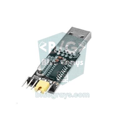
Installing drivers: Windows, macOS and Linux
| Operating system | What to do | Port name |
|---|---|---|
| Windows 10 / 11 | Windows Update usually installs the driver itself; if not, install CH341SER for the CH340 or the CP210x VCP driver for the CP2102 | COM3, COM4... under Device Manager > Ports (COM & LPT) |
| macOS | Current versions have built-in drivers for the CH340, CP2102 and FT232; don't stack old vendor drivers on top | /dev/cu.usbserial-..., or /dev/cu.wchusbserial... or /dev/cu.SLAB_USBtoUART with a vendor driver |
| Linux | Drivers are already in the kernel; add your user to the dialout group, and on Ubuntu remove the brltty package if the CH340 port disappears | /dev/ttyUSB0 |
If, after plugging in the adapter on Windows, you see a USB2.0-Serial with a yellow exclamation mark under Other devices in Device Manager, the CH340 driver is missing; if you see CP2102 USB to UART Bridge Controller, the CP2102 driver is missing. Once the driver is installed, unplug the adapter, plug it back in and look at Tools > Port in the Arduino IDE: the new port that appears at that moment is the adapter's. If nothing shows up at all, change the cable first; charging cables have no data wires. The full list of port, driver and permission problems is in Arduino code won't upload.
Loopback test: is the adapter working?
- Remove every wire from the adapter and plug it into the computer.
- With a jumper wire, connect the adapter's own TXD and RXD pins together.
- Select the adapter's port in the Arduino IDE and open the Serial Monitor; the speed doesn't matter for this test.
- Type something and send it. If your text comes straight back, the chip, driver and cable are fine; the problem lies in the wiring or the target board.
- If nothing comes back, check the port, the driver and the cable, and see whether the adapter's TX and RX LEDs flicker.
Programming an Arduino Pro Mini: auto-reset with DTR
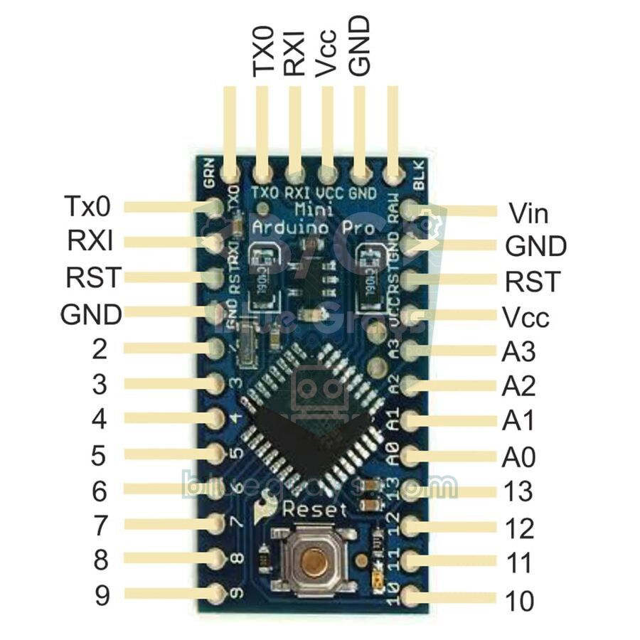
When code is uploaded to an Arduino, the board is reset first; the bootloader, which runs for about a second after reset, checks whether a new program is arriving over the serial port. The Uno and Nano do this reset on their own: there's a 100 nF capacitor between the USB chip's DTR line and the processor's RESET pin. The moment the IDE opens the port, DTR drops from HIGH to LOW, the capacitor passes this sudden drop to the RESET pin as a short LOW pulse and the board resets. On the Pro Mini the same capacitor sits on the board and connects to the GRN (or DTR) pin on the header; when you connect the adapter's DTR pin there, uploading is as easy as on an Uno.
| USB to TTL | Pro Mini | Note |
|---|---|---|
| GND | GND (or BLK) | Common ground |
| 5V or 3V3 | VCC | 5V for the 5 V / 16 MHz version, 3V3 for the 3.3 V / 8 MHz version |
| TXD | RXI | Crossed |
| RXD | TXO | Crossed |
| DTR | GRN (DTR) | Auto-reset; without it you have to reset by hand |
- Find out your board's version from the marking on the back or on its crystal: boards with a 16 MHz crystal are the 5 V version, 8 MHz ones are the 3.3 V version.
- Set the adapter's jumper to match the board version and wire it up according to the table.
- In the Arduino IDE choose Tools > Board > Arduino AVR Boards > Arduino Pro or Pro Mini.
- Under Tools > Processor, choose ATmega328P (5V, 16 MHz) or ATmega328P (3.3V, 8 MHz) to match your board.
- Select the adapter's port and upload the test sketch below; with DTR connected you don't need to press any button.
1// Pro Mini + USB-TTL testi: LED yanıp söner, gönderdiğin satır geri gelir
2// Pro Mini + USB-TTL test: the LED blinks and every line you send comes back
3const int LED = 13;                     // Pro Mini'nin dahili LED'i / Pro Mini onboard LED
4unsigned long sonDegisim = 0;
5bool ledAcik = false;
6
7void setup() {
8  Serial.begin(9600);
9  pinMode(LED, OUTPUT);
10  Serial.println(F("Pro Mini hazir / ready"));
11  Serial.print(F("Derlenen saat / compiled clock: "));
12  Serial.print(F_CPU / 1000000UL);      // 16 = 5 V sürüm, 8 = 3,3 V sürüm / 16 = 5 V board, 8 = 3.3 V board
13  Serial.println(F(" MHz"));
14}
15
16void loop() {
17  if (millis() - sonDegisim >= 500) {   // yarım saniyede bir / every half second
18    sonDegisim = millis();
19    ledAcik = !ledAcik;
20    digitalWrite(LED, ledAcik);
21  }
22  if (Serial.available()) {
23    String satir = Serial.readStringUntil('\n');   // satır sonuna kadar oku / read up to the line ending
24    satir.trim();
25    Serial.print(F("Geldi / received: "));
26    Serial.println(satir);
27  }
28}
When the upload finishes, the LED on the board blinks every half second. Open the Serial Monitor at 9600 baud with New Line selected, type something, and the text comes back. The F_CPU line in the code catches a small but important trap: the bootloaders of both Pro Mini versions upload at 57600 baud, so code uploads even with the wrong Processor option. But if you choose 16 MHz for an 8 MHz board, everything runs at half speed, the LED changes once a second and you only see garbage in the Serial Monitor. If your adapter has no DTR pin, you can time the upload by hand: the moment the IDE finishes compiling and shows Uploading... in the output, press and release the Pro Mini's reset button.
Uploading code to the ESP-01 and ESP32-CAM
On the ESP8266 and ESP32 the bootloader is built into the chip and checks the GPIO 0 pin at boot: if GPIO 0 is LOW it enters download mode and waits for code, if it's HIGH it runs the program in flash. Development boards have an auto-upload circuit that connects the DTR and RTS lines to EN and GPIO 0 through two transistors; esptool toggles these lines in sequence to put the board into download mode by itself. A plain USB to TTL adapter doesn't have this circuit, so you do it by hand: connect GPIO 0 to GND, reset the board, upload the code, then remove the GPIO 0 connection and reset again.
| USB to TTL (jumper at 3.3 V) | ESP-01 | ESP32-CAM |
|---|---|---|
| GND | GND | GND |
| TXD | RX | U0R (GPIO 3) |
| RXD | TX | U0T (GPIO 1) |
| Power | VCC and EN (CH_PD) from a separate 3.3 V regulator | From the adapter's 5V pin to the board's 5V pin |
| Upload mode | GPIO 0 to GND, touch RST to GND briefly | IO0 to GND, press the RST button |
| Arduino IDE board | Generic ESP8266 Module | AI Thinker ESP32-CAM |
The ESP-01 draws current peaks above 300 mA while connecting to Wi-Fi; the adapter's 3V3 pin can't supply that and the module keeps resetting. So use an AMS1117-3.3 regulator fed from the 5V pin. All of the ESP-01's connections and AT commands are in ESP-01 module, and the step-by-step ESP32-CAM upload is in How to use the ESP32-CAM. If you'd like a project that adds a PIR to the ESP32-CAM and sends the photo to your phone, have a look at ESP32-CAM photos to Telegram.
Reading serial logs: the USB to TTL as a second serial port
One of the adapter's least known yet most useful jobs is adding a second serial monitor to a board. While the board's own USB port is talking to a Python program, the Serial Plotter or another device, you can watch detailed debug messages on a separate port. The ESP32 has three hardware UARTs; the code below assigns UART2 to GPIO 16 and 17 and sends a log line to the adapter every second. Sending the letter r from the adapter resets the counter, so you can see that it works in both directions.
1// ESP32: USB portu Serial'de kalır, ikinci log kanalı USB-TTL'ye gider
2// ESP32: the USB port stays on Serial, a second log channel goes to the USB-TTL
3#define LOG_RX 16                       // USB-TTL TXD buraya / USB-TTL TXD goes here
4#define LOG_TX 17                       // USB-TTL RXD buraya / USB-TTL RXD goes here
5
6unsigned long sayac = 0;
7
8void setup() {
9  Serial.begin(115200);                                  // kartın kendi USB portu / the board's own USB port
10  Serial2.begin(115200, SERIAL_8N1, LOG_RX, LOG_TX);     // UART2: USB-TTL'ye / UART2: to the USB-TTL
11  Serial.println("Ana port / main port");
12  Serial2.println("Log portu hazir / log port ready");
13}
14
15void loop() {
16  sayac++;
17  int deger = analogRead(34);                            // GPIO 34'e bağlı bir sensör / a sensor on GPIO 34
18  Serial2.printf("[%lu ms] #%lu ADC=%d\n", millis(), sayac, deger);   // ayrıntılı log / detailed log
19  if (sayac % 10 == 0) Serial.println(deger);            // ana portta yalnız özet / only a summary on the main port
20
21  while (Serial2.available()) {                          // USB-TTL'den gelen komut / command from the USB-TTL
22    char c = Serial2.read();
23    if (c == 'r') {
24      Serial2.println("Sayac sifirlandi / counter reset");
25      sayac = 0;
26    }
27  }
28  delay(1000);
29}
To wire it up, set the adapter's jumper to 3.3 V and connect TXD to GPIO 16, RXD to GPIO 17 and GND to GND. Then, instead of opening a second Arduino IDE, you can use PuTTY, screen on macOS and Linux, or a small reader you write in Python; for the Python side see Arduino Python serial communication. On the Raspberry Pi Pico the same idea takes a few lines of MicroPython: UART0 is on GP0 (TX) and GP1 (RX), and the code both sends a log and echoes back the bytes it receives.
1# Raspberry Pi Pico (MicroPython): UART0 üzerinden USB-TTL'ye log ve yankı
2# Raspberry Pi Pico (MicroPython): log and echo to a USB-TTL over UART0
3from machine import UART, Pin
4import time
5
6uart = UART(0, baudrate=115200, tx=Pin(0), rx=Pin(1))   # GP0 = TX, GP1 = RX
7led = Pin(25, Pin.OUT)                                  # Pico dahili LED / Pico onboard LED (Pico W: "LED")
8sayac = 0
9son = time.ticks_ms()
10
11uart.write("Pico UART0 hazir / ready\r\n")
12while True:
13    if time.ticks_diff(time.ticks_ms(), son) >= 1000:   # saniyede bir log / one log line per second
14        son = time.ticks_ms()
15        sayac += 1
16        led.toggle()
17        uart.write("[%d ms] #%d\r\n" % (time.ticks_ms(), sayac))
18    if uart.any():                                      # USB-TTL'den gelen baytlar / bytes from the USB-TTL
19        veri = uart.read()
20        uart.write(b"Geldi / received: " + veri)
21    time.sleep_ms(10)
The same method lets you listen to what a module is saying with no Arduino in between. Connect a NEO-6M GPS module straight to the adapter and open it at 9600 baud, and you'll see NMEA sentences streaming in; open an HC-05 module in AT mode at 38400 baud and you can change its name and PIN. Everything about the Serial Monitor's line ending and baud settings is in Arduino Serial Monitor.
Common problems and fixes
| Symptom | Likely cause | Fix |
|---|---|---|
| The adapter isn't in the port list | Charging cable, missing driver or brltty on Linux | Use a data cable, install the driver, remove brltty |
| avrdude: stk500_getsync(): not in sync: resp=0x00 | TX-RX wired straight, DTR not connected or wrong board | Connect TX to RXI and RX to TXO; connect DTR to GRN or press reset when Uploading... appears |
| Code uploaded but the Serial Monitor shows garbage | Baud rate mismatch or the wrong MHz chosen for the Pro Mini | Set the Serial Monitor to the speed in the code, pick your board's real version in the Processor menu |
| Failed to connect to ESP8266 / ESP32 | GPIO 0 isn't LOW at boot, or TX-RX are reversed | Connect GPIO 0 to GND, then reset; check TX-RX |
| The ESP keeps restarting | The adapter's 3.3 V output can't handle the current peaks | Use a separate 3.3 V regulator and a 100–470 µF capacitor |
| The Pro Mini resets every time the Serial Monitor opens | DTR is connected; a reset when the port opens is normal | If you don't want the reset, remove the DTR wire after uploading |
| The computer shuts down the USB port when you plug in | A short circuit or two supplies clashing | Remove the wires; don't connect VCC if the target has its own supply |
The USB to TTL adapter is one of the smallest tools in your drawer and one of the ones you'll use most: it programs boards without USB, lets your computer talk to modules and shows you line by line what's happening inside your projects. If you remember to cross TX and RX, choose the right logic level and keep GND common, almost every problem disappears. In the BlueGrays app you'll find serial communication between two Arduinos, phone control over Bluetooth and ESP32 Wi-Fi projects, with step-by-step wiring diagrams and ready-to-use code.
Frequently asked questions
What is a USB to TTL adapter used for?
It converts your computer's USB port into the UART serial communication that microcontrollers use. That way you can upload code to boards without USB, such as the Arduino Pro Mini, ESP-01 and ESP32-CAM, read their serial messages and configure modules like GPS or Bluetooth straight from your computer.
Which is better, CH340 or CP2102?
In hobby projects both run without problems at 115200 baud and you won't notice a difference in practice. The CP2102 has an internal oscillator and a stronger 3.3 V output, and its inputs are 5 V tolerant; the CH340 is cheaper and more common. Current macOS and Linux versions have built-in drivers for both.
How do I connect TX and RX on a USB to TTL adapter?
They're crossed: the adapter's TXD pin goes to the target board's RX pin and its RXD pin to the target's TX pin. GND must always be shared. Reversing the lines does no harm, but nothing will be received; if you're not sure, swap them and try again.
How do I program an Arduino Pro Mini with a USB to TTL adapter?
Connect GND to GND, VCC to VCC, TXD to RXI, RXD to TXO and DTR to the GRN pin. In the Arduino IDE choose the Arduino Pro or Pro Mini board and the ATmega328P (5V, 16 MHz) or (3.3V, 8 MHz) option that matches your board, then upload as usual. Without DTR, press the reset button the moment Uploading... appears.
Should a USB to TTL adapter be 3.3 V or 5 V?
The logic level must match the target board: 5 V for the Uno, Nano and 5 V Pro Mini; 3.3 V for the ESP8266, ESP32 and Raspberry Pi Pico. On modules with a jumper you make this choice with the jumper. The CP2102 always outputs 3.3 V and its inputs tolerate 5 V, so it works with both kinds of boards.
Can an Arduino Uno be used as a USB to TTL adapter?
Yes. If you connect the Uno's RESET pin to GND or upload an empty sketch, its USB chip is exposed directly through D0 and D1. In that case the wiring is straight: the target's TX goes to D1 and its RX to D0. Because the Uno uses 5 V logic, add a voltage divider on the D0 line for 3.3 V boards.
Projects to build after reading this
See all projects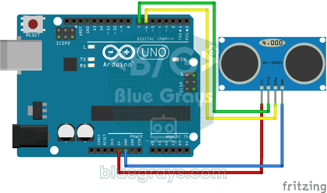
HC-SR04 Distance Measurement (Serial Display)
The HC-SR04 sensor works just like a bat finding its way in the dark: it sends out a sound you cannot hear, listens for the echo and measures how far away the object in front of it is. The Arduino wri
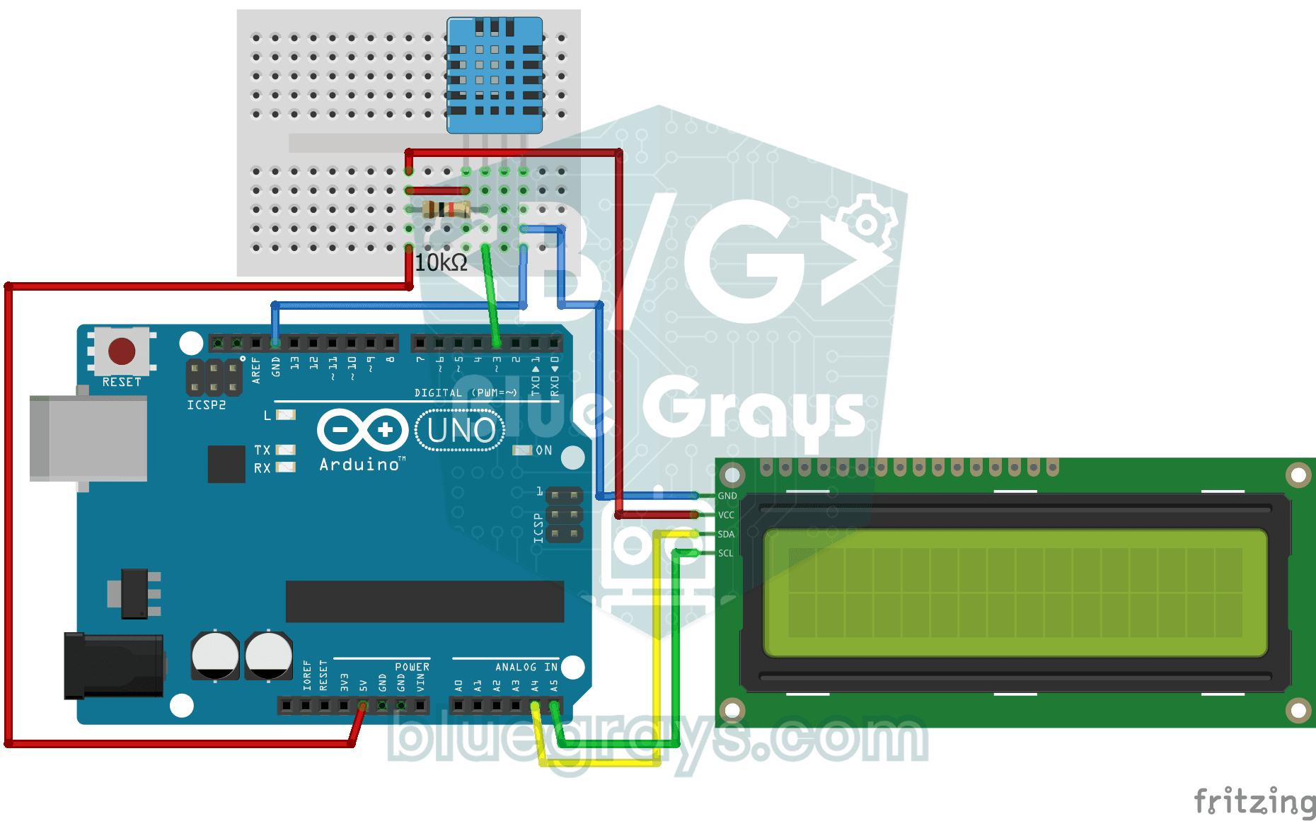
Temperature and Humidity with DHT11
How warm is your room, and is the air humid or dry? The DHT11 sensor measures temperature and humidity, and the Arduino writes the values on a two-line LCD screen, refreshing every couple of seconds.

LED Blink with ESP32
Teaches basic GPIO output usage with ESP32. We achieve a blinking effect by turning an LED on and off from a digital pin. ESP32 version of the classic blink project on Arduino UNO; the basic blink commands in the Arduino environment are the same, but the ESP32's pin layout and 3.3 V GPIO levels differ from those of the Arduino UNO.
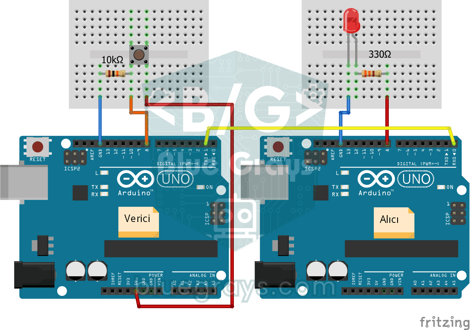
One-Way Communication Between 2 Arduinos
You get two Arduinos talking over a single wire: press the button on one and the LED on the other lights up, press it again and it goes off. The sending board reports the button press with a short mes
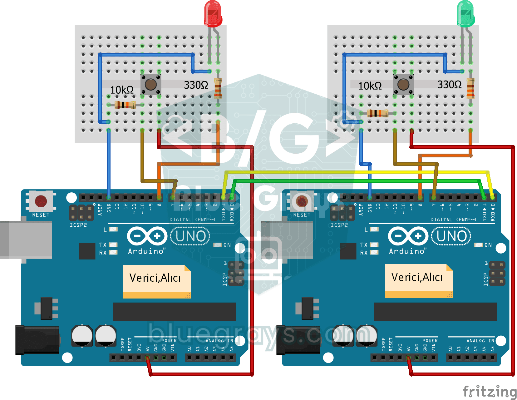
Two-Way Communication Between 2 Arduinos
Two Arduinos are wired together and talk to each other: press the button on one and the light on the other comes on, press it again and it goes off. Both boards run the same program, so each one both
Control an LED from Your Phone via Bluetooth
A small rehearsal for switching the lights in your room on and off from your phone. The Bluetooth module passes the letters sent from your phone to the Arduino; one letter turns on the red LED, anothe

ESP32 Wi-Fi STA Connection (with LCD Screen)
In this project, we connect the ESP32 to the home Wi-Fi network in Station (STA) mode in a secure, fault-tolerant manner. We store the SSID and password in a separate secrets.h file to prevent leaking to Git, set up an auto-reconnect mechanism, and display the RSSI signal level and IP address on an I2C LCD screen. The internal LED works as a status indicator. It is a production-grade connection manager.

ESP32 OTA Update — Wireless Firmware Installation (With LCD Screen)
In this project, you’ll learn how to upload new firmware to the ESP32 over Wi-Fi without a USB cable. Using the ArduinoOTA library, the ESP32 becomes visible on the network and is automatically listed as bluegrays-ota in the "Network port" tab of the Arduino IDE. The initial upload is done via USB, and all subsequent updates are wireless—a critical feature for field devices. The I2C LCD screen displays the Wi-Fi status, IP address, hostname, OTA upload percentage, and error messages in both