
ESP32 Failed to Connect Error Fix: BOOT Button, Driver, Cable
ESP32 "Failed to connect: Timed out waiting for packet header" error? Fix it with the BOOT button, CP2102/CH340 driver, a better cable and a 10 µF capacitor.

The ESP32 failed to connect error, in full "A fatal error occurred: Failed to connect to ESP32: Timed out waiting for packet header", is the most common problem when uploading code to an ESP32. The Arduino IDE finishes compiling, "Connecting........_____....." scrolls across the bottom pane, and after about 20 seconds the upload stops with this message. The short answer: the ESP32 could not enter download mode. Most of the time, holding the BOOT button on the board during upload fixes it instantly; if it doesn't, the cause is the cable, the USB driver (CP2102 or CH340), the wrong port, or a circuit connected to a boot pin such as GPIO0 or GPIO12.
In this guide you'll learn the mechanism behind the error, that is, which pins the ESP32 checks at startup to enter programming mode. Then come a five-minute checklist, driver installation, the 10 µF capacitor fix that lets you upload without ever pressing BOOT, and special wiring for the ESP32-CAM and bare ESP32-WROOM modules. If you're new to the ESP32, first take a look at What Is the ESP32?.
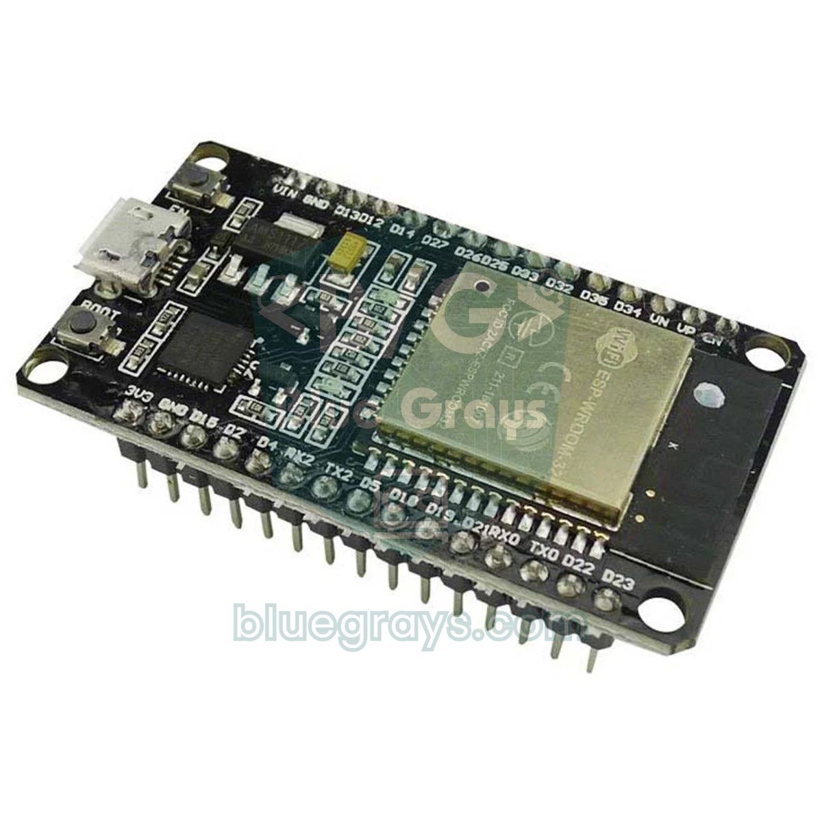
What is the Failed to connect error and why does it happen?
The Arduino IDE sends code to the ESP32 with a program called esptool. esptool talks over the serial port to the bootloader permanently stored in the chip's ROM. For this bootloader to start listening, the ESP32 must start up with GPIO0 LOW at the moment of reset. On development boards, an auto-reset circuit with two transistors connected to the USB-serial chip's DTR and RTS lines does this: esptool first resets the chip by pulling EN, holds GPIO0 LOW at the same time, and puts the chip into download mode. If any step of this sequence fails, esptool gets no reply to the sync packet it sends and reports "Timed out waiting for packet header". In other words, the error tells you the computer reached the port but the chip didn't respond as expected.
| Error message | Meaning | Where to look first |
|---|---|---|
| Failed to connect to ESP32: Timed out waiting for packet header | The chip didn't enter download mode or didn't reply | BOOT button, cable, 10 µF capacitor |
| Failed to connect to ESP32: No serial data received | No data is coming from the port at all (newer esptool versions) | Cable, port selection, TX/RX wiring |
| Wrong boot mode detected (0x13)! The chip needs to be in download mode | The chip booted in normal mode; GPIO0 wasn't LOW | BOOT button or a circuit connected to GPIO0 |
| Invalid head of packet (0x...): Possible serial noise or corruption | Data is arriving corrupted | Set Upload Speed to 115200, change the cable |
| Could not open port / Access is denied / Permission denied | The port is in use by another program or you lack permission | Close serial terminals; the dialout group on Linux |
| This chip is ESP32-S3, not ESP32. Wrong --chip argument? | The wrong board is selected in the Arduino IDE | Pick the correct chip under Tools > Board |
| MD5 of file does not match data in flash! | Connected, but writing to flash is corrupted | GPIO12, power supply, flash settings |
How does the ESP32 enter download mode? Strapping pins
At every startup, the moment reset is released, the ESP32 reads the state of a few pins and decides how to boot based on them. These are called strapping pins (boot configuration pins). After startup they can be used as normal inputs and outputs, but if they sit at the wrong level during reset, they cause upload or boot problems. If you set the serial monitor to 115200 baud, hold BOOT and press EN, and see the line "boot:0x3 (DOWNLOAD_BOOT(UART0/UART1/SDIO_REI_REO_V2)) waiting for download", the chip has entered the right mode. On a normal boot it prints "boot:0x13 (SPI_FAST_FLASH_BOOT)".
| Pin | Internal resistor | For download mode | What happens if wrong? |
|---|---|---|---|
| GPIO0 | Pull-up | LOW (BOOT button held) | Code runs, no upload (boot:0x13) |
| GPIO2 | Pull-down | LOW or floating | Upload stops with "Timed out" |
| GPIO12 (MTDI) | Pull-down | LOW or floating | Flash is powered at 1.8 V; writing and booting break |
| GPIO15 (MTDO) | Pull-up | Doesn't matter | If LOW, boot messages go silent |
| GPIO5 | Pull-up | Doesn't matter | Affects SDIO timing, usually causes no problems |
| EN (CHIP_PU) | External 10 kΩ pull-up | HIGH after reset | If stuck LOW, the chip doesn't run at all |
Step-by-step fix: a 5-minute checklist
- Try the BOOT button: Press Upload, and as soon as "Connecting..." appears in the bottom pane, hold the BOOT button; release it when the "Writing at 0x00010000..." lines start to scroll.
- Change the cable: Many cables left over from phone chargers have no data lines. If you don't hear the computer's new-device sound when you plug the board in, the cable is the first suspect.
- Check the port: Under Tools > Port, plug and unplug the board to see which port appears and disappears, and select that one.
- Install the driver: Read the name of the USB chip on the board (CP2102, CH340 or CH9102) and install the matching driver.
- Select the right board: Use "ESP32 Dev Module" for classic ESP32 boards, and the dedicated board definitions for the ESP32-S3 and C3.
- Lower the speed: Reduce Tools > Upload Speed from 921600 to 115200.
- Strip the circuit: Remove anything connected to GPIO0, GPIO2, GPIO12, GPIO1 (TX) and GPIO3 (RX), and try with the board plugged into USB only.
- Check the power: Plug the board straight into a rear port of the computer instead of a USB splitter; front-panel ports and passive hubs may supply too little current.
USB cable and port selection
Cable problems are so common that the first question on forums is always "have you tried another cable?" Cables made only for charging have no D+ and D− data wires; the board's light comes on but the computer sees no serial port. On long, thin, cheap cables the data lines pick up noise and cause errors like "Invalid head of packet". Use a good-quality data cable shorter than one metre. If the port list has several options (for example COM1 and COM5), COM1 is usually the motherboard's own port; the ESP32 is the number newly added to the list when you plug the board in. If the board vanishes from the port list every few seconds, the problem isn't in software; look at the cable, the USB port or the power side.
CP2102 and CH340 driver installation
The classic ESP32 chip itself can't speak USB; a small USB-to-serial converter chip on the board translates the computer's USB into the chip's UART0 lines (GPIO1 TX, GPIO3 RX). Without the right driver for this chip, the port never appears or stays as an unknown device with a yellow exclamation mark in Device Manager. You can find out which chip you have from the text on the small IC right next to the USB port. For more on converters, see the USB-TTL Converter article.
| Chip | USB ID (VID:PID) | Driver | Name shown in Windows |
|---|---|---|---|
| CP2102 / CP2104 | 10C4:EA60 | Silicon Labs CP210x VCP | Silicon Labs CP210x USB to UART Bridge (COMx) |
| CH340 / CH340C | 1A86:7523 | WCH CH341SER | USB-SERIAL CH340 (COMx) |
| CH9102 | 1A86:55D4 | WCH CH343SER | USB-Enhanced-SERIAL CH9102 (COMx) |
| FT232RL (external adapter) | 0403:6001 | FTDI VCP | USB Serial Port (COMx) |
| ESP32-S3 / C3 built-in USB | 303A:1001 | Not needed on Windows 10/11 | USB Serial Device (COMx) |
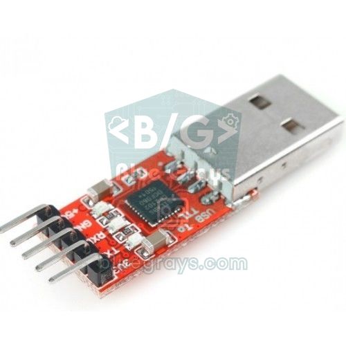
On Windows you should see the board's name under Device Manager > Ports (COM & LPT). Newer versions of macOS mostly recognise CP210x and CH34x chips on their own; the port looks like /dev/cu.usbserial-XXXX or /dev/cu.SLAB_USBtoUART. On Linux the port is /dev/ttyUSB0, and if you get "Permission denied" you need to add your user to the dialout group (sudo usermod -a -G dialout $USER) and log out and back in. If the CH340 disappears right after being plugged in on Ubuntu, the brltty package installed for screen readers may be claiming the port; removing that package fixes it. To see automatically which port belongs to which chip, you can run this small Python script on your computer (requires pyserial):
1# Bilgisayardaki seri portları ve USB yongalarını listeler / Lists serial ports and USB chips
2# Kurulum / Install: pip install pyserial
3from serial.tools import list_ports
4
5CHIPS = {
6    (0x10C4, 0xEA60): "CP2102 / CP2104",
7    (0x1A86, 0x7523): "CH340",
8    (0x1A86, 0x55D4): "CH9102",
9    (0x0403, 0x6001): "FT232RL",
10    (0x303A, 0x1001): "ESP32-S3 / C3 dahili USB / native USB",
11}
12
13ports = list_ports.comports()
14if not ports:
15    print("Port yok: kablo ya da surucu / No ports: cable or driver")
16for p in ports:
17    chip = CHIPS.get((p.vid, p.pid), "bilinmiyor / unknown")   # VID:PID eşleşmesi / VID:PID match
18    print(p.device, "|", p.description, "|", chip)
The 10 µF capacitor fix: upload without pressing BOOT
On some cheap ESP32 boards you have to press the BOOT button on every upload. The cause is usually the timing of the auto-reset circuit: EN must go back HIGH while GPIO0 is still LOW. If the capacitor on EN on your board is too small or missing, the chip wakes up after GPIO0 is released and boots in normal mode. The fix is to add a 10 µF capacitor between EN and GND. If you use an electrolytic capacitor, the long leg (+) goes to EN and the short leg (−) to GND. Together with the board's 10 kΩ pull-up resistor the time constant is τ = R × C = 10 kΩ × 10 µF = 0.1 seconds; so EN rises slowly and the chip wakes up while GPIO0 is still LOW. You can try different values with the RC time constant calculator. For testing, it's enough to plug the capacitor into the board's EN and GND pins on a breadboard; for a permanent fix, solder it across these two pins. For capacitor types, see What Is a Capacitor?.
Arduino IDE settings: board, speed and serial port
- Board: Choose "ESP32 Dev Module" for classic DevKits and "AI Thinker ESP32-CAM" for the ESP32-CAM. Choosing the wrong chip gives a "Wrong --chip argument" error.
- Upload Speed: The default 921600 is unstable on some CH340 boards and long cables; 115200 is slow but the safest value.
- Flash Mode and Frequency: If you get errors while writing, try setting Flash Mode to DIO and Flash Frequency to 40 MHz.
- Programs holding the port: If a terminal program using the same port, a second IDE window or 3D printer software is open, the port is busy; close them all.
- ESP32 board package: A very old esp32 package may not recognise newer chip revisions; update to the latest version in Boards Manager. The Installing the Arduino IDE article helps with the setup steps.
- Erase All Flash: If previously uploaded code keeps resetting and locking the port, turn on Erase All Flash Before Sketch Upload in the Tools menu and upload while holding BOOT.
Did the upload succeed? Test code
1// Yükleme testi: çip bilgisini yazdırır, dahili LED'i yakıp söndürür / Upload test: prints chip info, blinks the onboard LED
2const int LED_PIN = 2;            // çoğu DevKit'te dahili LED / onboard LED on most DevKits
3bool ledOn = false;
4
5void setup() {
6  Serial.begin(115200);
7  delay(500);
8  pinMode(LED_PIN, OUTPUT);
9  Serial.println();
10  Serial.println("Yukleme basarili / Upload OK");
11  Serial.printf("Cip / Chip: %s rev %d\n", ESP.getChipModel(), (int)ESP.getChipRevision());
12  Serial.printf("Cekirdek / Cores: %d\n", (int)ESP.getChipCores());
13  Serial.printf("Flash: %u MB\n", (unsigned)(ESP.getFlashChipSize() / (1024 * 1024)));
14  Serial.printf("Cip kimligi / Chip ID: %012llX\n", (unsigned long long)ESP.getEfuseMac());
15}
16
17void loop() {
18  ledOn = !ledOn;
19  digitalWrite(LED_PIN, ledOn ? HIGH : LOW);   // saniyede bir yanıp söner / blinks once per second
20  delay(500);
21}
After this code is uploaded, set the serial monitor to 115200 baud and press the EN button. If you see the chip model (e.g. ESP32-D0WD-V3), its revision, the core count and the flash size, both uploading and serial communication work fine; the onboard LED on GPIO 2 also blinks once per second. If you see garbage characters, the baud rate is wrong; if you see nothing, the problem isn't the upload but the serial monitor settings. The Arduino Serial Monitor article covers this in detail. Since GPIO 2 is also a strapping pin, if you connect an external LED there, use a series resistor and don't add a pull-up resistor.
Uploading code to the ESP32-CAM
The AI Thinker ESP32-CAM board has no USB port or auto-reset circuit, so the failed to connect error is much more common here. To upload code you need either a USB-TTL converter (FT232RL, CP2102, CH340) or the ESP32-CAM-MB adapter that plugs in under the board. What matters is that IO0 is connected to GND during upload and that the chip is reset in that state. There's a small RST button on the back of the camera side of the board. Even with the MB adapter, you sometimes have to hold the IO0 button on the adapter and press the ESP32-CAM's RST button. For camera projects, take a look at the ESP32-CAM article.
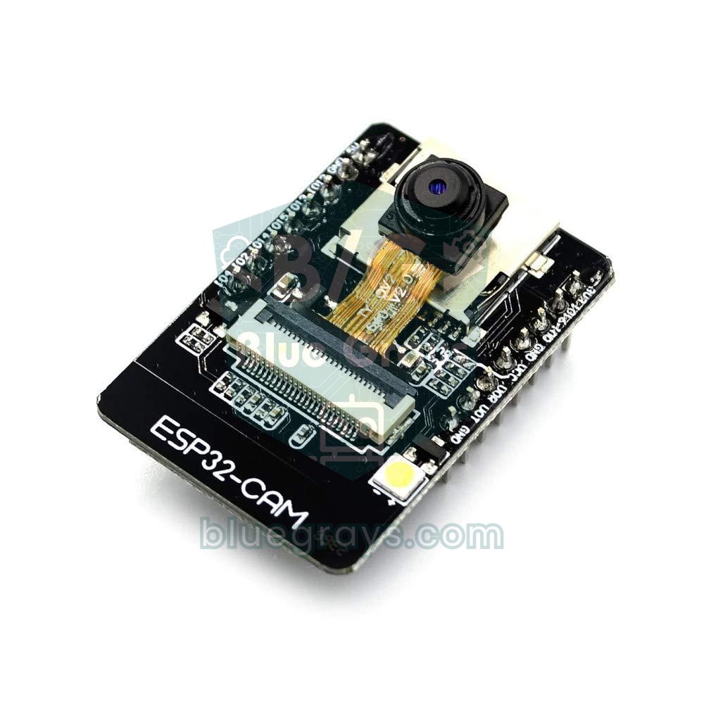
| USB-TTL pin | ESP32-CAM | Bare ESP32-WROOM module | Note |
|---|---|---|---|
| 5V (VCC) | 5V | — | Power the ESP32-CAM from the 5V pin |
| 3.3V | — | 3V3 (an external regulator is recommended) | The adapter's 3.3 V output is often insufficient |
| GND | GND | GND | A common ground is essential |
| TX | U0R (GPIO3) | RXD0 (GPIO3) | Cross-connected |
| RX | U0T (GPIO1) | TXD0 (GPIO1) | Cross-connected |
| — | IO0 → GND (during upload) | GPIO0 → GND (BOOT button) | Remove after the upload |
| DTR / RTS (if present) | Not used | To the auto-reset circuit | Optional |
- Set the USB-TTL adapter's logic-level selector to 3.3 V and connect it according to the table.
- Fit a jumper wire between IO0 and GND.
- In the Arduino IDE, select the AI Thinker ESP32-CAM board and the correct port; for large sketches, use a suitable Partition Scheme.
- Press the board's RST button once; you should see "waiting for download" in the serial monitor.
- Press Upload; if "Connecting..." takes long, press RST once more.
- When the upload finishes, remove the IO0-GND wire and press RST to run the code.
Minimum circuit for a bare ESP32 module (WROOM)
If you're designing your own board or using the ESP32-WROOM-32 module directly, you have to build everything a development board provides ready-made. The minimum programming circuit consists of: a 3.3 V regulator that can deliver at least 500 mA (e.g. AMS1117 3.3V) with 10 µF and 100 nF capacitors right next to it; on the EN pin a 10 kΩ pull-up to 3V3, a 1 µF capacitor to GND and a reset button to GND; on GPIO0 a 10 kΩ pull-up and a BOOT button to GND. Cross-connect the TX0 and RX0 lines to the adapter. To upload, hold BOOT, press and release RESET, then release BOOT. If you want automatic uploading, you can connect the adapter's DTR and RTS lines to EN and GPIO0 with the same cross-coupled two-NPN-transistor circuit used on DevKits. GPIO6–GPIO11 are connected to the flash memory inside the module; never connect anything to them, or the chip can't read the flash and the upload fails. You can check pin functions in the pinout tool.
Common mistakes and fixes
| Symptom | Likely cause | Fix |
|---|---|---|
| Port list is empty | Charge-only cable or missing driver | Use a data cable, install the CP2102/CH340 driver |
| "Connecting...." then Timed out | The chip isn't entering download mode | Hold BOOT or add 10 µF between EN and GND |
| Error only when the circuit is connected | A module connected to GPIO0, GPIO2, GPIO12 or TX/RX | Move the connection to another pin |
| Upload cuts off halfway | Insufficient power or a noisy cable | Rear USB port, short cable, 115200 baud |
| Board keeps resetting, port disappears | The uploaded code is crashing or brownout | Connect while holding BOOT, upload with Erase All Flash |
| Upload finished but code doesn't run | The board is still in download mode | Remove the IO0 connection, press EN/RST |
| Port exists on Mac/Linux but no access | Permissions or a conflicting program | dialout group, remove brltty |
Although the Failed to connect error looks scary, it almost always comes from a small hardware detail: a button, a cable, a driver or a module connected to the wrong pin. If you work through the checklist in order, most boards start accepting code again within a few minutes. If you have similar problems with Arduino boards, the Arduino Code Won't Upload article may also help. Once your board accepts code reliably, you can continue in the BlueGrays app with ESP32 projects such as LED blinking, button control, a traffic light and OTA updates, complete with step-by-step circuit diagrams and code.
Frequently asked questions
What does the BOOT button do on the ESP32?
The BOOT button pulls GPIO0 to GND. If the ESP32 sees GPIO0 LOW at reset, instead of running its own code it waits for new code over the serial port from the bootloader in ROM. On boards whose auto-reset circuit works properly you don't need to press it; on boards where it doesn't, you have to hold it during upload.
My ESP32 doesn't show up on my computer. What should I do?
First change the cable; charge-only cables have no data lines. Then read the board's USB chip (CP2102, CH340 or CH9102), install the matching driver, and check whether a new COM port appears under Ports in Device Manager. If the board still doesn't appear, try a different USB port.
Do I have to press the BOOT button on every upload?
No. This is usually caused by a shortcoming in the board's auto-reset timing. Adding a 10 µF capacitor between EN and GND makes EN rise more slowly, and most boards will then accept code without pressing the button. On an electrolytic capacitor, the positive leg must go to EN.
Is CP2102 or CH340 better for the ESP32?
Both program the ESP32 without trouble; the difference is mostly the driver. CP2102 boards need the Silicon Labs driver and CH340 boards need the WCH driver. Because some CH340 boards can be unstable at 921600 baud, lowering the upload speed to 460800 or 115200 is a good precaution.
Why won't code upload to my ESP32-CAM?
The ESP32-CAM has no auto-reset circuit, so IO0 must be connected to GND during upload and the board must be reset with the RST button in that state. The adapter's TX must also be cross-connected to U0R and RX to U0T, and the board must be powered from the 5V pin with enough current. Don't forget to remove the IO0-GND connection after the upload.
Does the Timed out waiting for packet header error mean my board is broken?
Most of the time, no; the error usually just means download mode wasn't entered. If you set the serial monitor to 115200 baud, press EN and see boot messages, the chip is fine. If no LED lights up, the regulator gets very hot and the port never appears, there may be a hardware fault on the board.
Projects to build after reading this
See all projects
ESP32 Built-in LED Blink
Blinking the built-in blue LED on the ESP32 DevKit V1. No external components required! The first project you should try when you buy an ESP32. GPIO 2 is connected to the built-in LED.

LED Blink with ESP32
Teaches basic GPIO output usage with ESP32. We achieve a blinking effect by turning an LED on and off from a digital pin. ESP32 version of the classic blink project on Arduino UNO; the basic blink commands in the Arduino environment are the same, but the ESP32's pin layout and 3.3 V GPIO levels differ from those of the Arduino UNO.

ESP32 LED Control with Push Button (Push)
The LED lights up when the button is pressed and turns off when released. Shows how the ESP32's digital input pin and internal pull-up resistor are used. The INPUT_PULLUP mode eliminates the need for an external resistor.

ESP32 LED Control with Pushbutton (Toggle)
Each time the button is pressed the state of the LED changes: if it is on it turns off, if it is off it turns on. Classic toggle pattern. With debounce we clean up the mechanical noise of the pushbutton to ensure a single toggle with a single press.

ESP32 Traffic Light
Real traffic light simulation with 3 LEDs red-yellow-green. Timings close to real traffic logic: red long, yellow short, green long. Classic example of sequential GPIO control.

Reading Light Intensity with the ESP32 LDR Module
Real-time monitoring of the LDR module's raw ADC value and relative light percentage calculated from dark and light reference values in the Serial Monitor. This percentage is not a lux measurement. Teaches the module’s calibration logic. It is ideal to complete this before Project 10, as it is used to determine the threshold value.

ESP32 OTA Update — Wireless Firmware Installation (With LCD Screen)
In this project you'll learn to upload new firmware to the ESP32 over Wi-Fi, without a USB cable. With the ArduinoOTA library the ESP32 becomes visible on the network and shows up automatically as bluegrays-ota under "Network port" in the Arduino IDE. The first upload goes over USB; after that every update is wireless, a key feature for devices out in the field.

ESP32 Wi-Fi STA Connection (with LCD Screen)
In this project, we connect the ESP32 to the home Wi-Fi network in Station (STA) mode in a secure, fault-tolerant manner. We store the SSID and password in a separate secrets.h file to prevent leaking to Git, set up an auto-reconnect mechanism, and display the RSSI signal level and IP address on an I2C LCD screen. The internal LED works as a status indicator. It is a production-grade connection manager.