
Hall Effect Sensor Arduino: A3144 and 49E for Magnets and RPM
Hall effect sensor Arduino: A3144 digital and KY-024 / 49E analog sensors, pull-up, pole and field strength, RPM counting, door sensor, ESP32 Hall vs reed.
A Hall effect sensor is a small semiconductor chip that detects the presence, polarity and strength of a magnet without any moving parts. In Arduino projects it's used to count a motor's RPM, measure bicycle speed, tell whether a door is open or closed, or read the position of a joystick. The flip cover that switches off your phone's screen, the speed signal of a computer cooling fan and the wheel speed sensors in cars all work with the Hall effect. In hobby kits you'll usually meet two types: the digital A3144, which gives an on/off signal, and the analog 49E (KY-024 module), which outputs the field strength as a voltage.
In this guide we'll explain the physics of the Hall effect in plain words, then show the difference between digital and analog sensors, how to wire them and why they need a pull-up resistor. After that we'll detect a magnet with the A3144, measure which pole is approaching and how many gauss the field is with the 49E, and count a motor's RPM using an interrupt. You'll also find what the ESP32's built-in Hall sensor is good for and why newer versions removed it, MicroPython code for the Raspberry Pi Pico and a comparison of the Hall sensor with the reed switch.
What is the Hall effect and how does a Hall sensor work?
In 1879 Edwin Hall discovered that when a magnetic field is applied at right angles to a thin conductor carrying a current, a small voltage appears between the conductor's two edges. The reason is that moving charges are pushed sideways in a magnetic field (the Lorentz force): electrons pile up on one edge of the plate, the other edge is left short, and the difference is measured as the Hall voltage. This voltage is proportional to the field strength and its sign flips when the field direction changes. The effect is much stronger in semiconductors than in metals, but it's still only in the microvolt to millivolt range. That's why Hall sensor chips contain, next to the Hall plate, a regulator, an amplifier and, in digital models, a Schmitt trigger and an output transistor.
Magnetic field strength is measured in gauss (G) or millitesla (mT); 1 mT = 10 G. The Earth's magnetic field is about 0.25–0.65 G, so it doesn't affect Hall sensors. The surface of a small neodymium magnet has a few thousand gauss, and this falls very quickly with distance: double the distance and the field drops to roughly an eighth. That's why the detection distance, depending on the sensor's threshold and the size of the magnet, is usually between a few millimetres and a few centimetres.
Types of Hall sensor: A3144, KY-024 / 49E and others
Hall sensors fall into three main groups by their output. In unipolar switch types such as the A3144, the output goes LOW only when one pole (the south pole on the A3144) comes close enough, and returns HIGH when the magnet moves away. In latch types such as the US1881, the south pole sets the output to one state, the north pole to the other, and the last state is kept even after the magnet has gone; this type is ideal for motors with alternating N–S magnets around them. In linear types such as the 49E, the output isn't a switch but an analog voltage proportional to the field strength: with no magnet it sits at half the supply voltage, rises when one pole approaches and falls with the other.
| Feature | A3144 (digital) | 49E / SS49E (analog) | US1881 (latch) |
|---|---|---|---|
| Supply | 4.5–24 V | 2.7–6.5 V | 3.5–24 V |
| Output | Open collector, LOW at the magnet | Analog, VCC/2 at zero field | Open drain, LOW at S, HIGH at N |
| Responds to | South pole (S) only | Both, with sign | S switches on, N switches off |
| Threshold / sensitivity | Operate point about 70–350 G | Typically 1.4 mV/G at 5 V | Typically ±95 G |
| Needs a pull-up? | Yes (10 kΩ or INPUT_PULLUP) | No | Yes |
| Module name | KY-003 | KY-024 (with DO via LM393), KY-035 | Rare as a module |
| Pins (printed face towards you) | VCC, GND, OUT | VCC, GND, OUT | VDD, GND, OUT |
Hall sensor Arduino wiring and the pull-up resistor
The A3144's output is an open-collector transistor: with a magnet present it connects the output to GND, and with no magnet it connects the output to nothing, leaving it floating. A floating pin reads random HIGH and LOW values from noise. So the output has to be pulled up to the supply side through a resistor; this is called a pull-up. On an Arduino, the easiest way is to turn on the board's internal 20–50 kΩ resistor with pinMode(pin, INPUT_PULLUP). If the cable is long, the environment is noisy or you're counting a fast-spinning shaft, an external 10 kΩ between the output and the supply gives cleaner edges. The open collector has a handy side effect: if you power the sensor from 5 V and pull the output up to 3.3 V, 3.3 V boards like the ESP32 and Pico can use it safely too.
| Connection | Arduino Uno | ESP32 | Raspberry Pi Pico |
|---|---|---|---|
| A3144 VCC | 5V | VIN (5 V) | VBUS (5 V) |
| A3144 OUT | D2 + INPUT_PULLUP (or 10 kΩ → 5V) | GPIO 27 + INPUT_PULLUP (or 10 kΩ → 3V3) | GP15 + PULL_UP (or 10 kΩ → 3V3) |
| 49E VCC | 5V | 3V3 | 3V3 |
| 49E OUT | A0 | GPIO 34 | GP26 (ADC0) |
| GND (both) | GND | GND | GND |
Detecting a magnet with the A3144
- With the A3144's printed face towards you, the pins from left to right are VCC, GND and OUT. Connect VCC to 5V, GND to GND and OUT to D2.
- Upload the code below and open the Serial Monitor at 9600 baud.
- Bring one face of the magnet close to the printed face of the sensor. If the board's built-in LED doesn't light, turn the magnet over; the A3144 only responds to the south pole.
- Note the distances at which the LED switches on and off; the difference between them is the sensor's built-in hysteresis.
1const byte HALL_PIN = 2;              // A3144 OUT
2const byte LED_PIN = 13;              // dahili LED / onboard LED
3
4bool lastMagnet = false;
5
6void setup() {
7  pinMode(HALL_PIN, INPUT_PULLUP);    // açık kolektör çıkış için pull-up / pull-up for the open-collector output
8  pinMode(LED_PIN, OUTPUT);
9  Serial.begin(9600);
10}
11
12void loop() {
13  bool magnet = digitalRead(HALL_PIN) == LOW;   // mıknatıs varken LOW / LOW when a magnet is present
14  digitalWrite(LED_PIN, magnet ? HIGH : LOW);
15
16  if (magnet != lastMagnet) {                   // yalnız durum değişince yaz / print only on change
17    Serial.println(magnet ? F("Miknatis var / magnet detected") : F("Miknatis yok / no magnet"));
18    lastMagnet = magnet;
19  }
20}
Unlike a reed switch or a button, the A3144 needs no debouncing. The Schmitt trigger inside the sensor makes sure the operate point (BOP) is at least 20 G above the release point (BRP); even if the magnet wobbles at the limit, the output doesn't bounce back and forth. Because there's no moving contact, the output edges are clean and it can trigger thousands of times per second. Remember that the logic is inverted: with INPUT_PULLUP you read LOW when the magnet is present and HIGH when it isn't; it's the same pull-up logic as in button wiring.
Measuring pole and field strength with the KY-024 / 49E
The 49E is a linear sensor: powered from 5 V, its output sits at about 2.5 V with no magnet and typically changes by 1.4 mV per gauss. When the south pole approaches the printed face, the voltage rises; with the north pole it falls. This lets you measure not just whether a magnet is there but which pole is approaching and how strong the field is: B (G) = (Vout − Vzero) / 0.0014. On the KY-024 module, the AO pin is the 49E's output directly; the DO pin is the digital output of the LM393 comparator, which changes when the field passes the threshold you set with the potentiometer. The code below measures the zero point at start-up, then prints the field in gauss and millitesla and tells you the pole.
1const byte HALL_PIN = A0;               // 49E OUT ya da KY-024 AO / 49E OUT or KY-024 AO
2const float VCC = 5.0;
3const float SENSITIVITY = 0.0014;       // 1,4 mV/G (5 V'ta tipik) / 1.4 mV/G (typical at 5 V)
4const float DEAD_BAND = 20.0;           // bu değerin altını yok say (G) / ignore below this (G)
5
6float zeroVolt = 2.5;
7
8float readVolt() {
9  long sum = 0;
10  for (byte i = 0; i < 32; i++) sum += analogRead(HALL_PIN);   // 32 ölçüm ortalaması / average of 32 readings
11  return sum / 32.0 * VCC / 1023.0;
12}
13
14void setup() {
15  Serial.begin(9600);
16  delay(200);
17  zeroVolt = readVolt();                // mıknatıs yokken sıfır noktası / zero point with no magnet nearby
18  Serial.print(F("Sifir / zero: "));
19  Serial.print(zeroVolt, 3);
20  Serial.println(F(" V"));
21}
22
23void loop() {
24  float gauss = (readVolt() - zeroVolt) / SENSITIVITY;
25  Serial.print(gauss, 0);
26  Serial.print(F(" G  ("));
27  Serial.print(gauss / 10.0, 1);        // 10 G = 1 mT
28  Serial.print(F(" mT)  "));
29  if (gauss > DEAD_BAND)       Serial.println(F("Guney kutbu / south pole"));
30  else if (gauss < -DEAD_BAND) Serial.println(F("Kuzey kutbu / north pole"));
31  else                         Serial.println(F("Alan yok / no field"));
32  delay(250);
33}
The Uno's 10-bit ADC divides 5 V into 1024 steps, so one step is about 4.9 mV; with the 49E that means a resolution of roughly 3.5 G. Because pole labelling can vary between manufacturers, check it with a compass on your first try: the end of the compass needle that points north turns towards the magnet's south pole. The sensor saturates at about ±1000 G; if you almost touch it with a very strong magnet, the value stops rising. The zero point can drift by a few millivolts with temperature, so for precise measurements repeat the zeroing just before you measure.
Measuring RPM and speed with a Hall sensor
To measure the RPM of a motor, fan or wheel, you stick a small magnet on the shaft or rim and fix the A3144 where the magnet passes in front of it once per turn. On each pass the output goes LOW once. Trying to catch the pulses with digitalRead() in loop() misses pulses at high speed; the right method is an interrupt. The code below measures the time between two pulses to the microsecond and calculates the speed with RPM = 60,000,000 / (period_µs × number_of_magnets). If no pulse arrives for 2 seconds, the shaft is considered stopped. We explain how interrupts work in detail in the Arduino interrupt guide.
1const byte HALL_PIN = 2;                  // A3144 OUT, Uno'da kesme pini (INT0) / interrupt pin on the Uno (INT0)
2const byte MAGNETS = 1;                   // mildeki mıknatıs sayısı / magnets on the shaft
3const unsigned long MIN_GAP_US = 2000;    // 2 ms'den sık darbeler gürültüdür / pulses closer than 2 ms are noise
4const unsigned long STOP_US = 2000000;    // 2 sn darbe yoksa durdu / no pulse for 2 s means stopped
5
6volatile unsigned long lastPulse = 0;
7volatile unsigned long period = 0;        // iki darbe arası süre (µs) / time between pulses (µs)
8
9void onPulse() {
10  unsigned long now = micros();
11  unsigned long gap = now - lastPulse;
12  if (gap > MIN_GAP_US) {
13    period = gap;
14    lastPulse = now;
15  }
16}
17
18void setup() {
19  pinMode(HALL_PIN, INPUT_PULLUP);
20  attachInterrupt(digitalPinToInterrupt(HALL_PIN), onPulse, FALLING);   // mıknatıs gelince LOW'a iner / falls LOW when the magnet arrives
21  Serial.begin(9600);
22}
23
24void loop() {
25  noInterrupts();                         // iki değişkeni birlikte oku / read both variables together
26  unsigned long p = period;
27  unsigned long last = lastPulse;
28  interrupts();
29
30  float rpm = 0;
31  if (p > 0 && micros() - last < STOP_US) {
32    rpm = 60000000.0 / ((float)p * MAGNETS);
33  }
34  Serial.print(F("RPM: "));
35  Serial.println(rpm, 0);
36  delay(500);
37}
The code uses a 2 ms lockout, which means that with one magnet you can measure up to 30,000 RPM, more than enough for most hobby motors. If you put two or four magnets on the shaft, you get a measurement that updates more often at low speed; just change MAGNETS. Place the magnets evenly; weight on one side makes a fast-spinning shaft vibrate. The yellow wire of a computer fan is actually an open-collector output from a Hall sensor inside and gives two pulses per revolution; use the same code with MAGNETS = 2 to read a fan's RPM. You'll find the circumference and km/h maths for a bike speedometer in the reed switch guide; the formula is the same with a Hall sensor.
A door and lid sensor with a Hall sensor
For a door sensor, put the magnet on the moving leaf of the door and the A3144 on the frame, so that when the door is closed the magnet's south pole faces the sensor's printed face. With the door closed the output is LOW; when it opens it goes HIGH. Even if the wire breaks, the pull-up pulls the pin HIGH and the system sees it as "door open", so a fault stays on the safe side. The Hall sensor has two advantages here: with no moving contact it doesn't wear out on vibrating doors or lids that open and close many times a second, and it detects the magnet even through the wall of a sealed box. The downside is that it uses power all the time: the A3144 draws about 4–5 mA, which would drain a 2000 mAh battery in about 18 days for the sensor alone. For a door sensor that has to run on batteries for months, a reed switch that uses no power is a better fit.
The ESP32's built-in Hall sensor
The original ESP32 chip contains a small Hall sensor, and in the 2.x versions of the Arduino ESP32 core you can read it with the hallRead() function. But this sensor is very noisy and only shows a clear change when a strong magnet almost touches the module's metal shield; it also uses GPIO 36 and GPIO 39 while measuring, so if anything else is connected to those pins the results are spoiled. Newer chips like the ESP32-S2, S3 and C3 don't have it at all, and since Espressif removed support in ESP-IDF 5, hallRead() no longer exists in the Arduino ESP32 3.x core. The code below compiles on both versions: on 2.x it prints the average value, on 3.x it shows a warning instead. For a serious project, connecting an external A3144 or 49E to the ESP32 is always better; you'll find the board's general features in what is an ESP32.
1// ESP32 dahili Hall sensörü (yalnız orijinal ESP32) / built-in Hall sensor (original ESP32 only)
2void setup() {
3  Serial.begin(115200);
4}
5
6void loop() {
7#if ESP_ARDUINO_VERSION_MAJOR < 3
8  long sum = 0;
9  for (int i = 0; i < 100; i++) {
10    sum += hallRead();              // GPIO 36 ve 39'u kullanır / uses GPIO 36 and 39
11  }
12  Serial.println(sum / 100);        // gürültülü, ortalama al / noisy, so average it
13#else
14  Serial.println("hallRead() 3.x cekirdekte yok / not available in core 3.x");
15#endif
16  delay(200);
17}
Measuring RPM with the Raspberry Pi Pico (MicroPython)
On the Pico, power the A3144 with 5 V from VBUS, connect its output to GP15 and turn on the pin's internal pull-up resistor; since this resistor goes to 3.3 V, the pin never sees 5 V. The code below counts the pulses with an interrupt and reads and resets the counter every second. Briefly disabling interrupts while reading the counter stops a pulse from slipping in between reading and resetting and getting lost. With one magnet this method has a resolution of 60 RPM; for a finer result you can measure the time between two pulses with time.ticks_us(), as in the Arduino example.
1from machine import Pin, disable_irq, enable_irq
2import time
3
4hall = Pin(15, Pin.IN, Pin.PULL_UP)    # A3144 OUT (sensör VBUS'tan 5 V ile) / A3144 OUT (sensor on 5 V from VBUS)
5MAGNETS = 1                            # mildeki mıknatıs sayısı / magnets on the shaft
6count = 0
7last_us = 0
8
9def on_pulse(pin):
10    global count, last_us
11    now = time.ticks_us()
12    if time.ticks_diff(now, last_us) > 2000:    # 2 ms gürültü filtresi / 2 ms noise filter
13        count += 1
14        last_us = now
15
16hall.irq(trigger=Pin.IRQ_FALLING, handler=on_pulse)
17
18while True:
19    time.sleep(1)
20    state = disable_irq()              # sayacı güvenle oku / read the counter safely
21    pulses = count
22    count = 0
23    enable_irq(state)
24    print("RPM:", pulses * 60 // MAGNETS)
Hall sensor or reed switch?
Both detect a magnet, but in completely different ways. A reed switch is a mechanical switch in which two metal blades inside a glass tube touch when a magnet comes near, and it uses no power at all. A Hall sensor is an electronic chip with no moving parts that needs a supply. The short rule: a reed switch for a sensor that triggers rarely and has to run on batteries for months; a Hall sensor for a fast-spinning shaft, a vibrating environment or any job that needs pole information or field strength.
| Feature | Hall sensor (A3144 / 49E) | Reed switch |
|---|---|---|
| How it works | Semiconductor, no moving parts | Mechanical contact |
| Supply | Required (about 4–6 mA) | Not required |
| Pole and strength | A3144 south only; 49E gives pole and strength | Pole doesn't matter, just present / absent |
| Speed | Up to tens of kHz, clean edges | Hundreds of Hz, contact bounce |
| Life and robustness | Doesn't wear, handles vibration | Millions of operations, glass can break |
| Best use | RPM, speed, position, pole detection | Battery door and window sensors |
Project ideas with a Hall sensor
- Bike speedometer: Put a magnet on a spoke and an A3144 on the fork; show speed, distance and average speed on an OLED display.
- Motor and fan tachometer: Measure the RPM of a DC motor or computer fan and watch the real speed while you adjust it with PWM.
- Anemometer: Fit a magnet to the shaft of a cup rotor, calculate wind speed from the RPM and log it with an ESP32.
- Water flow meter: Flow sensors like the YF-S201 also have a Hall sensor inside; count the pulses to measure litres, details in the water flow sensor guide.
- Secret box or drawer lock: A 49E hidden inside the lid opens the lock only when a magnet is held at exactly the right spot.
- Door and lid alarm: An alarm with an A3144 that sounds a buzzer or sends a notification to your phone via an ESP32 when a lid is opened.
Common mistakes and how to fix them
| Symptom | Likely cause | Fix |
|---|---|---|
| The pin reads random HIGH and LOW | No pull-up on the A3144 output | Use INPUT_PULLUP or put 10 kΩ between the output and VCC |
| Nothing happens when the magnet approaches | Wrong pole: the A3144 only responds to the south pole | Turn the magnet over and hold it square to the printed face |
| The sensor is unstable on the ESP32 or Pico | The A3144 runs on 3.3 V | Power the sensor from 5 V and connect the pull-up to 3.3 V |
| RPM low or erratic at high speed | Pulses are read in loop() and get missed | Use an interrupt with attachInterrupt() |
| The 49E shows a value with no magnet | The zero point isn't 2.5 V or has drifted | Measure the zero point at start-up and subtract it |
| ESP32 hallRead() won't compile | You're using the Arduino ESP32 3.x core | Use an external Hall sensor or switch to the 2.x core |
A Hall sensor is the most flexible way to detect a magnet without contact, noise or wear: the A3144 gives you a fast, clean on/off signal, the 49E gives you pole and field strength, and interrupts give you reliable RPM measurement. As long as you remember the pull-up resistor, the right pole and the supply detail on 3.3 V boards, it works on the first try. In the BlueGrays app you'll find the Reed Switch Reading and Reed Switch Door Sensor projects, along with button and interrupt examples, the ESP32 motion alarm and Pico debounce projects, with step-by-step circuit diagrams and code.
Frequently asked questions
How does a Hall effect sensor work?
A Hall sensor contains a thin semiconductor plate carrying a current. When a magnetic field hits the plate at right angles, the charges are pushed to one edge and a small voltage proportional to the field appears between the two edges. An amplifier inside the sensor boosts this voltage; in digital models a threshold circuit turns it into an on/off output.
Why does the A3144 need a pull-up resistor?
The A3144's output is open collector: with a magnet present it connects the output to GND, and without one it connects it to nothing. A floating pin reads random values from noise, so the output has to be pulled up to the supply through a resistor. On an Arduino, INPUT_PULLUP is enough; with long cables and high speeds an external 10 kΩ is better.
Which pole does the A3144 respond to?
The A3144 is a unipolar switch and only pulls its output LOW when the south pole comes close enough to its printed face. If you bring the north pole near, nothing happens. If you don't know the magnet's pole, try both faces or check it with a linear sensor like the 49E.
What is the difference between the KY-024 and the KY-003?
The KY-003 is a module with a digital A3144 sensor and only tells you whether a magnet is there or not. The KY-024 carries a linear 49E sensor and an LM393 comparator; its AO pin gives the field strength as an analog value, and its DO pin gives a digital signal based on a threshold you set with the potentiometer.
How far away can a Hall sensor detect a magnet?
The distance depends on the magnet's strength and the sensor's threshold. A small neodymium magnet usually triggers an A3144 from 1–3 cm; with a weak ferrite magnet that drops to a few millimetres. Because the magnetic field falls off very quickly with distance, the most effective way to increase the range is a bigger or stronger magnet.
Can you use the ESP32's built-in Hall sensor?
The original ESP32 has a built-in Hall sensor, and in the Arduino ESP32 2.x core you can read it with hallRead(). But it's very noisy, only notices a very close and strong magnet, and uses GPIO 36 and 39. It isn't present on the ESP32-S2, S3 and C3, and hallRead() has been removed from the Arduino ESP32 3.x core; use an external sensor for serious projects.
Projects to build after reading this
See all projects
LED Control with a Push Button (Push)
Just like a doorbell: the light stays on as long as you press, and goes off when you let go. The Arduino keeps listening to the button; while it's pressed the LED is on, and the moment you lift your f

ESP32 LED Control with Push Button (Push)
The LED lights up when the button is pressed and turns off when released. Shows how the ESP32's digital input pin and internal pull-up resistor are used. The INPUT_PULLUP mode eliminates the need for an external resistor.
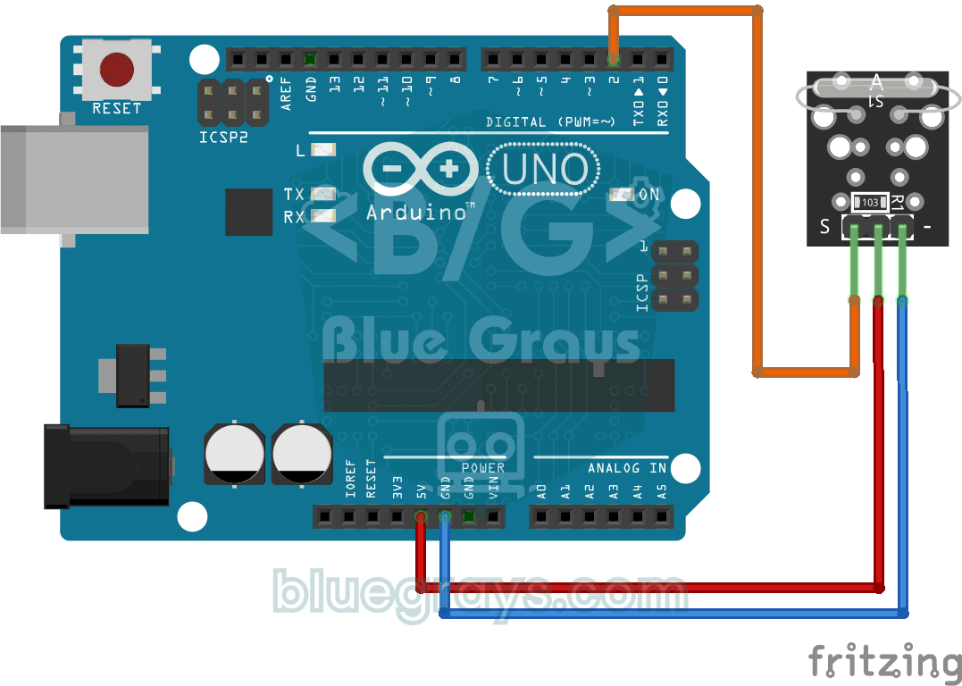
Reading a Reed Switch
Ever wondered about the magnetic switch inside door and window alarms? When a magnet comes near the reed relay module, the tiny switch inside it closes; the Arduino reads it once a second and prints 0
Reed Switch Door Sensor
Tell whether your door is open or closed just by looking at a light. You attach a small magnet to the door and a magnet-sensing switch to the frame; when the door is closed they sit side by side and t
ESP32 Motion Alarm System (PIR + Buzzer + LED + Telegram)
A smart security alarm system that activates the buzzer and LED when the PIR sensor detects motion, while simultaneously sending an instant notification to the owner via Telegram. It includes a 30-second cooldown to limit the frequency of repeated alarms; this mechanism does not validate PIR detections or eliminate false triggers. Suitable for home security, garage monitoring, warehouses, or workrooms. With ESP32-CAM, photo notifications can be added; with the classic ESP32 DevKit V1, text notif
Raspberry Pi Pico Button Debounce: IRQ vs Software Polling
Press a button once, code counts 3-4? That is contact bounce — metal contacts oscillate for microseconds! Compare 2 counting methods side-by-side in Serial: RAW polling (catches bounce, over-counts) vs IRQ + software debounce (accurate). Learn contact bounce physics, software debounce (ticks_diff() > 50ms), Pin.irq() interrupt registration, IRQ_FALLING trigger, ISR handlers, global + ISR safety. LED toggles via IRQ (visual feedback). Serial shows both counters per press
Motion Detector with Motion Sensor
A simple guard that tells you when someone walks into the room. The motion sensor picks up the warmth given off by the human body, and the Arduino keeps the LED on as long as there is movement and tur