
Arduino Interrupts: attachInterrupt, ISR Rules and Debouncing
How to use Arduino interrupts: attachInterrupt, Uno pins 2 and 3, RISING/FALLING/CHANGE, volatile, debouncing, encoder and RPM examples, plus ESP32 and Pico.
An Arduino interrupt makes the processor drop whatever it's doing the moment a change you're waiting for happens on a pin (or a timer event fires) and run a special function you've written. In short, instead of constantly asking "has the button been pressed?" inside loop(), you tell the Arduino "let me know when it's pressed". You do this with the attachInterrupt() function; on the Arduino Uno the interrupt pins are D2 and D3, while on the ESP32 and the Raspberry Pi Pico almost every GPIO can trigger an interrupt.
Interrupts are essential for counting very fast pulses without missing any (encoders, speed sensors, water flow sensors), catching a short event in the middle of a long task and waking a board from sleep. In this guide you'll see step by step how an interrupt works in hardware, which pins you can use on each board, the difference between the RISING, FALLING and CHANGE modes, the rules for writing an interrupt service routine (ISR), how to debounce a button, and examples for a button, an encoder and an RPM counter. At the end you'll also learn about IRAM_ATTR on the ESP32 and using irq with MicroPython on the Pico.
What is an interrupt and how does it work?
Think of a doorbell: without one, you'd have to walk to the door every minute to check whether someone had arrived. That's called polling, and reading a pin with digitalRead() inside loop() is exactly that. The doorbell is an interrupt: it rings while you're busy with something else, you stop, check the door and go back to what you were doing. A microcontroller works the same way. When the change you selected happens on the pin, the hardware sets an interrupt flag; the processor finishes the current instruction, saves its registers, jumps through the interrupt vector to your ISR (Interrupt Service Routine) and, once the ISR ends, carries on in loop() exactly where it left off. On the Uno this switch takes only a few microseconds.
| Feature | Polling | Interrupt |
|---|---|---|
| How it works | loop() reads the pin over and over | Hardware catches the change and runs the ISR |
| Response time | The slower loop() is, the bigger the delay | A few microseconds |
| With delay() in the code | Events can be missed | Events are still caught |
| Very fast pulses | Get missed | Are counted one by one |
| Code complexity | Simple | Needs volatile and atomic reads |
| Best for | Buttons, slow sensors | Encoders, speed and flow sensors, waking from sleep |
Which pins support interrupts? Arduino, ESP32 and Pico
| Board | External interrupt pins | Note |
|---|---|---|
| Arduino Uno R3, Nano, Pro Mini | D2, D3 | D2 = INT0, D3 = INT1 |
| Arduino Uno R4 (Minima / WiFi) | D2, D3 | The pins listed in the official Arduino reference |
| Arduino Mega 2560 | 2, 3, 18, 19, 20, 21 | 20 and 21 can't be used for interrupts while they're used for I2C |
| Arduino Leonardo, Micro | 0, 1, 2, 3, 7 | 0 and 1 are also the serial port pins |
| Arduino Nano Every | All digital pins | ATmega4809 processor |
| ESP32 | All GPIOs | GPIO 34–39 are input-only and have no internal pull-up |
| ESP8266 (NodeMCU) | All except GPIO 16 (D0) | ISRs must be marked IRAM_ATTR |
| Raspberry Pi Pico / Pico W | All of GP0–GP28 | Pins are 3.3 V, never apply 5 V |
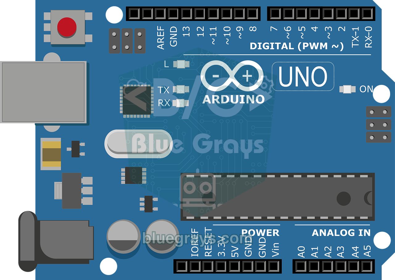
In your code, don't pass the pin number directly; convert it to an interrupt number with digitalPinToInterrupt(pin), because the interrupt number changes from board to board: on the Uno D2 is interrupt 0 and D3 is interrupt 1, while on the Leonardo interrupt 0 is D3 and interrupt 1 is D2. If you need more than two interrupts on the Uno, pin change interrupts (PCINT) work on almost every pin; however, they only tell you that "something changed", and all pins on the same port share a single ISR. The PinChangeInterrupt and EnableInterrupt libraries make them easier to use. You'll find your board's full pin map in the Pinout tool and the Uno's pin functions in the Arduino Uno pinout article.
Using attachInterrupt and the interrupt modes
The syntax is attachInterrupt(digitalPinToInterrupt(pin), ISR, mode). The second parameter is the name of the function that runs when the interrupt fires; this function takes no parameters and returns nothing (void). The third parameter sets which event triggers the interrupt. Use detachInterrupt(digitalPinToInterrupt(pin)) to switch an interrupt off, noInterrupts() to pause all interrupts for a moment and interrupts() to turn them back on.
| Mode | When does it fire? | Typical use |
|---|---|---|
| LOW | Over and over for as long as the pin is LOW | Waking from sleep |
| CHANGE | On every change (both edges) | Encoders, measuring pulse length, debouncing |
| RISING | When going from LOW to HIGH (rising edge) | Start of a sensor pulse, button with pull-down |
| FALLING | When going from HIGH to LOW (falling edge) | Pressing a button with pull-up, open-collector sensors |
| HIGH | For as long as the pin is HIGH | Only on the Due, Zero and MKR1000; ONHIGH on the ESP32 |
Pick the mode to suit your circuit. If you wired the button with INPUT_PULLUP, the pin is normally HIGH and drops to LOW when pressed, so FALLING catches the press. Use LOW mode with care: as long as the pin stays LOW the ISR runs again and again and loop() barely moves. That's why it's usually only used to wake the board from sleep; to wake the Uno from its deepest sleep mode (power-down), the datasheet recommends a LOW level interrupt or a pin change interrupt. On the ESP32, the LOW and HIGH constants don't work as interrupt modes the way you'd expect: LOW doesn't enable the interrupt at all and HIGH behaves like a rising edge. For level interrupts there you write ONLOW and ONHIGH.
First example: counting button presses with an interrupt
- Connect one leg of the button to D2 and the other to GND. No external resistor is needed; we'll use the internal pull-up.
- Upload the code below and open the Serial Monitor at 9600 baud.
- Press the button a few times and watch the counter go up. Despite the delay(500) inside loop(), no press is missed.
- Don't be surprised if the number sometimes jumps by 2 or 3 at once: that's contact bounce, and we'll fix it shortly.
1const byte BUTTON_PIN = 2;                // kesme pini D2 (INT0) / interrupt pin D2 (INT0)
2volatile unsigned int pressCount = 0;     // ISR ile paylaşılan sayaç / counter shared with the ISR
3
4void onPress() {                          // ISR: kısa ve hızlı / ISR: short and fast
5  pressCount++;
6}
7
8void setup() {
9  Serial.begin(9600);
10  pinMode(BUTTON_PIN, INPUT_PULLUP);      // dahili pull-up, buton GND'ye / internal pull-up, button to GND
11  attachInterrupt(digitalPinToInterrupt(BUTTON_PIN), onPress, FALLING);
12}
13
14void loop() {
15  noInterrupts();                         // 2 baytlık değeri güvenle kopyala / copy the 2-byte value safely
16  unsigned int count = pressCount;
17  interrupts();
18
19  Serial.print(F("Basis / Presses: "));
20  Serial.println(count);
21  delay(500);                             // loop yavaş olsa da basış kaçmaz / presses are not missed even if loop is slow
22}
There are three important points in this code. First, onPress() just adds one to the counter and ends right away; an ISR's job is to note the event, not to do the work. Second, the counter is declared volatile, so the compiler doesn't keep it in a register and read a stale value, but fetches the fresh value from memory every time. Third, loop() turns interrupts off for a moment while it reads the counter. An unsigned int is 2 bytes on the Uno, and the 8-bit processor reads it in two steps. When the counter goes from 255 to 256, that is from 0x00FF to 0x0100, loop() first reads the low byte (0xFF); if the interrupt fires right then and increments the counter, it then reads the high byte (0x01) and the result is 0x01FF, or 511. Because this bug shows up very rarely, it's also hard to track down. On AVR boards the ATOMIC_BLOCK(ATOMIC_RESTORESTATE) macro from util/atomic.h gives the same protection; single-byte variables such as bool and byte don't have this problem.
ISR rules: keep it short, use volatile, no delay
- Keep it short and fast: while an ISR runs, other interrupts wait. On the Uno the millis() counter and the serial port also rely on interrupts, so a long ISR throws off timing and can make you lose incoming serial data. An ideal ISR finishes in a few microseconds.
- Don't use delay(): delay() measures time with counters updated by the Timer0 interrupt; inside an ISR interrupts are off, so it doesn't work. You can read millis(), but it doesn't advance during the ISR, and micros() starts returning wrong values after 1–2 ms. If you really need a very short wait, delayMicroseconds() works.
- Don't use Serial.print(): sending serial data also depends on interrupts; it makes the ISR longer and blocks if the buffer fills up. Leave the printing to loop().
- Make shared variables volatile: every variable used both in the ISR and in loop() must be declared volatile.
- Read multi-byte variables atomically: in loop(), copy int, long, float and unsigned long variables between noInterrupts() and interrupts().
- No parameters, no return value: an ISR must be void and take no parameters; data is exchanged through global variables.
- Keep heavy work out of the ISR: writing to an I2C display, saving to an SD card or calling libraries that need interrupts themselves, such as Wire, will hang inside an ISR.
Reading a button with an interrupt and debouncing it
When you press a mechanical button, the metal contacts don't settle immediately; they open and close several times for roughly 0.1 to 10 milliseconds. loop() may be too slow to notice, but an interrupt catches every edge, so a single press can produce 3–5 interrupts. What's more, bounce happens not only when you press but also when you release, so code that uses only FALLING with a time lockout can double-count when you hold the button for a while and let go. The code below uses CHANGE mode and only accepts a press when the pin is LOW and the line had been quiet for at least 50 ms before. That filters out both press and release bounce.
1const byte BUTTON_PIN = 2;                // kesme pini / interrupt pin
2const byte LED_PIN = 13;                  // dahili LED / onboard LED
3const unsigned long QUIET_MS = 50;        // gereken sessizlik süresi / required quiet time
4
5volatile bool ledState = false;           // ISR ile paylaşılır / shared with the ISR
6
7void onButtonChange() {                   // iki kenarda da çalışır / runs on both edges
8  static unsigned long lastEdgeMs = 0;
9  unsigned long now = millis();           // ISR'de okunur ama artmaz / readable in an ISR but does not advance
10  bool pressed = (digitalRead(BUTTON_PIN) == LOW);
11
12  if (pressed && now - lastEdgeMs > QUIET_MS) {   // hat sessizdi: gerçek basış / line was quiet: real press
13    ledState = !ledState;
14  }
15  lastEdgeMs = now;                       // her kenar süreyi yeniden başlatır / every edge restarts the timer
16}
17
18void setup() {
19  pinMode(LED_PIN, OUTPUT);
20  pinMode(BUTTON_PIN, INPUT_PULLUP);
21  attachInterrupt(digitalPinToInterrupt(BUTTON_PIN), onButtonChange, CHANGE);
22}
23
24void loop() {
25  digitalWrite(LED_PIN, ledState ? HIGH : LOW);   // bool tek bayt, okuması atomik / bool is one byte, atomic read
26  // burada uzun işler olsa da basış kaçmaz / long tasks here will not make you miss a press
27}
Besides software, you can also suppress bounce in hardware: put a 100 nF capacitor across the button and a 10 kΩ pull-up resistor on the pin, and the time constant becomes τ = R × C = 10 kΩ × 100 nF = 1 ms, which smooths out short bounces; the Schmitt trigger on the Uno's inputs cleans up the edge as well. You can work out other values with the RC time constant tool. To be honest, for buttons pressed by hand you often don't need an interrupt at all; if loop() is fast, polling is enough. For pull-up, pull-down and debouncing with millis(), see How to connect a button to Arduino. Save interrupts for fast, short signals.
Reading a rotary encoder with an interrupt
As you turn a rotary encoder (such as the KY-040), it produces square waves on two pins called CLK and DT that are shifted relative to each other. When you turn it quickly, the pulses get shorter than a millisecond and polling easily misses steps. The simplest method is to connect CLK to an interrupt pin and check the level of DT the moment CLK falls: if DT is HIGH it turned one way, if it's LOW the other. This version counts one step per click; if the direction comes out reversed, swap the ++ and -- lines. Cheap encoders bounce too, so adding a 10–100 nF capacitor between CLK and GND and between DT and GND makes a clear difference. For a version that puts both pins on interrupts and uses a state table to never miss a step, have a look at the rotary encoder (KY-040) guide.
1const byte PIN_CLK = 2;                   // kesme pini / interrupt pin
2const byte PIN_DT = 4;                    // normal dijital giriş / regular digital input
3
4volatile long position = 0;               // 4 baytlık konum / 4-byte position
5
6void onClkFall() {
7  if (digitalRead(PIN_DT) == HIGH) {      // yön DT seviyesinden / direction from the DT level
8    position++;
9  } else {
10    position--;
11  }
12}
13
14void setup() {
15  Serial.begin(115200);
16  pinMode(PIN_CLK, INPUT_PULLUP);
17  pinMode(PIN_DT, INPUT_PULLUP);
18  attachInterrupt(digitalPinToInterrupt(PIN_CLK), onClkFall, FALLING);
19}
20
21void loop() {
22  static long lastPos = 0;
23
24  noInterrupts();                         // atomik kopya / atomic copy
25  long pos = position;
26  interrupts();
27
28  if (pos != lastPos) {
29    Serial.println(pos);
30    lastPos = pos;
31  }
32}
Counting revolutions: measuring motor RPM
Measuring the speed of a motor or wheel is the classic use of interrupts. As the sensor you use either a slotted optical speed sensor with an LM393 and a 20-slot encoder disc, or a Hall sensor such as the A3144 with a magnet stuck to the shaft. Every slot or every pass of the magnet produces one pulse. From the number of pulses counted in one second, the speed is: RPM = pulses per second × 60 / pulses per revolution. For example, if a 20-slot disc gives 100 pulses per second, the motor is turning at 100 × 60 / 20 = 300 RPM.
1const byte SENSOR_PIN = 3;                // kesme pini D3 (INT1) / interrupt pin D3 (INT1)
2const byte PULSES_PER_REV = 20;           // diskteki yarık sayısı / slots on the encoder disc
3
4volatile unsigned long pulseCount = 0;
5
6void onPulse() {
7  pulseCount++;
8}
9
10void setup() {
11  Serial.begin(9600);
12  pinMode(SENSOR_PIN, INPUT_PULLUP);
13  attachInterrupt(digitalPinToInterrupt(SENSOR_PIN), onPulse, FALLING);
14}
15
16void loop() {
17  static unsigned long lastMs = 0;
18
19  if (millis() - lastMs >= 1000) {        // her saniye hesapla / compute once per second
20    lastMs += 1000;
21
22    noInterrupts();                       // kopyala ve sıfırla / copy and reset
23    unsigned long pulses = pulseCount;
24    pulseCount = 0;
25    interrupts();
26
27    float rpm = pulses * 60.0 / PULSES_PER_REV;
28    Serial.print(F("RPM: "));
29    Serial.println(rpm, 1);
30  }
31}
Here loop() copies and resets the counter every second; both happen inside the same noInterrupts() block so that no pulse is lost if an interrupt arrives between the two. With a 20-slot disc the resolution is 3 RPM. If you want more precise results at low speeds, instead of counting pulses, measure the time between two pulses in the ISR with micros() and use RPM = 60,000,000 / (period_µs × pulses per revolution). The same method works for the YF-S201 water flow sensor, speed measurement with a Hall sensor and the wheel speed of a geared DC motor.
A short note on timer interrupts
Interrupts don't only come from pins. The timers inside the microcontroller can also generate interrupts at fixed intervals, so a function runs exactly every 1 ms or every 500 ms no matter what loop() is doing. The Uno has three timers, and some of them are already used by Arduino's own functions:
| Timer | Size | Used by | PWM pins |
|---|---|---|---|
| Timer0 | 8-bit | millis(), delay(), micros() | 5, 6 |
| Timer1 | 16-bit | Servo library, TimerOne | 9, 10 |
| Timer2 | 8-bit | tone(), IRremote | 3, 11 |
On the Uno the easiest route is the TimerOne library: Timer1.initialize(500000) sets the period in microseconds and Timer1.attachInterrupt(function) attaches the ISR that runs every 500 ms. Because it uses Timer1, it clashes with the Servo library and with analogWrite() on pins 9 and 10. On the ESP32 with Arduino core 3.x, a timer interrupt is set up with timerBegin(1000000), timerAttachInterrupt() and timerAlarm(); timerAlarmWrite() and timerAlarmEnable() from 2.x were removed, so old examples fail with a "was not declared in this scope" error. On the Pico, MicroPython's Timer(period=500, mode=Timer.PERIODIC, callback=function) sets up a periodic interrupt in a single line. For how timers relate to PWM, see What is PWM?
Interrupts on the ESP32: IRAM_ATTR and portMUX
On the ESP32 you don't need to look for a special pin; every GPIO can trigger an interrupt. Only GPIO 34–39 have no internal pull-up, so a button there needs an external 10 kΩ pull-up; Espressif's errata also notes that GPIO 36 and 39 can produce false interrupts while the ADC is in use. The real difference on the ESP32 is the IRAM_ATTR attribute written in front of the ISR. It places the function in fast internal RAM (IRAM) instead of flash. While writing to flash (Preferences, SPIFFS, OTA) the cache is switched off; depending on the configuration, an interrupt that touches code in flash at that moment can reset the board with "Guru Meditation Error: Core 1 panic'ed (Cache disabled but cached memory region accessed)". The ESP8266 is even stricter: an ISR without IRAM_ATTR stops the board with the message "ISR not in IRAM!" as soon as attachInterrupt is called.
1const int BUTTON_PIN = 27;                // her GPIO kesme verebilir / any GPIO can interrupt
2const int LED_PIN = 2;                    // çoğu DevKit'te dahili LED / onboard LED on most DevKits
3const uint32_t QUIET_MS = 50;             // gereken sessizlik süresi / required quiet time
4
5volatile uint32_t pressCount = 0;
6portMUX_TYPE mux = portMUX_INITIALIZER_UNLOCKED;   // paylaşılan veri kilidi / lock for shared data
7
8void IRAM_ATTR onButtonChange() {         // ISR IRAM'de çalışır / ISR runs from IRAM
9  static uint32_t lastEdgeMs = 0;
10  uint32_t now = millis();
11  bool pressed = (digitalRead(BUTTON_PIN) == LOW);
12
13  if (pressed && now - lastEdgeMs > QUIET_MS) {
14    portENTER_CRITICAL_ISR(&mux);
15    pressCount++;
16    portEXIT_CRITICAL_ISR(&mux);
17  }
18  lastEdgeMs = now;
19}
20
21void setup() {
22  Serial.begin(115200);
23  pinMode(LED_PIN, OUTPUT);
24  pinMode(BUTTON_PIN, INPUT_PULLUP);
25  attachInterrupt(digitalPinToInterrupt(BUTTON_PIN), onButtonChange, CHANGE);
26}
27
28void loop() {
29  static uint32_t lastCount = 0;
30
31  portENTER_CRITICAL(&mux);               // loop tarafında kilit / lock on the loop side
32  uint32_t count = pressCount;
33  portEXIT_CRITICAL(&mux);
34
35  if (count != lastCount) {
36    lastCount = count;
37    digitalWrite(LED_PIN, (count % 2) ? HIGH : LOW);   // her basışta LED değişir / LED toggles on every press
38    Serial.printf("Basis / Press: %lu\n", (unsigned long)count);
39  }
40}
Because the ESP32 runs FreeRTOS and has two cores, shared variables are protected with a portMUX_TYPE lock instead of the Uno's noInterrupts(): use portENTER_CRITICAL_ISR() inside the ISR and portENTER_CRITICAL() in loop(). Reading a 32-bit variable is already a single step on the ESP32, but the lock is essential for things like reading and resetting a value or updating several variables together. If you want to attach the same function to several pins, attachInterruptArg() lets you pass a parameter, such as the pin number, to the ISR. For ESP32 basics see What is the ESP32?, and for tasks and cores see ESP32 FreeRTOS and dual core.
Interrupts on the Raspberry Pi Pico: MicroPython irq
On the Raspberry Pi Pico every pin from GP0 to GP28 can trigger an interrupt. In MicroPython you set one up with the pin object's irq() method: for trigger you pass Pin.IRQ_FALLING, Pin.IRQ_RISING or both combined, and handler is the function that runs when the interrupt fires; it receives the triggering pin as its parameter. Python has no volatile; declaring the variables you change in the ISR as global is enough. To measure time, use time.ticks_ms() and the overflow-safe time.ticks_diff(). The code below brings the quiet-time logic from the Arduino example to the Pico:
1from machine import Pin
2import time
3
4led = Pin("LED", Pin.OUT)                 # dahili LED (Pico ve Pico W) / onboard LED (Pico and Pico W)
5button = Pin(14, Pin.IN, Pin.PULL_UP)     # buton GP14 ile GND arasında / button between GP14 and GND
6
7QUIET_MS = 50                             # gereken sessizlik süresi / required quiet time
8presses = 0
9last_edge = time.ticks_ms()
10
11def on_change(pin):                       # handler tetikleyen pini alır / handler receives the pin
12    global presses, last_edge
13    now = time.ticks_ms()
14    if pin.value() == 0 and time.ticks_diff(now, last_edge) > QUIET_MS:
15        presses += 1
16        led.toggle()
17    last_edge = now
18
19button.irq(trigger=Pin.IRQ_FALLING | Pin.IRQ_RISING, handler=on_change)
20
21while True:
22    print("Basis / Presses:", presses)    # ana döngü uyurken bile basışlar sayılır / presses are counted while the loop sleeps
23    time.sleep(1)
On the Pico, irq runs as a soft interrupt by default: MicroPython queues the function and runs it as soon as possible, so using print or creating a list inside it causes no trouble, but latency goes up a little. If you pass hard=True, latency drops to microseconds; in return you can't allocate memory inside the ISR, so a new list, a string and even a float calculation can raise a "MemoryError". If you program the Pico from the Arduino IDE (Earle Philhower core), attachInterrupt() works the same on every GPIO. For setup see What is the Raspberry Pi Pico?, and for the basic commands see MicroPython basics.
Project ideas that use interrupts
- Reaction timer: measure how long it takes you to press the button after an LED lights up, using micros() in the ISR for sub-millisecond accuracy.
- Bike speedometer: put a magnet on the wheel and a Hall sensor on the frame; calculate speed and distance from the time per revolution.
- Water meter: count the pulses of a YF-S201 flow sensor and display the litres used.
- Robot car that drives straight: measure the speed of both motors with wheel encoders and match them.
- Menu control: browse an on-screen menu and change settings with a rotary encoder.
- Battery-powered alarm: let the output of a PIR sensor wake the board while it sleeps; for the ESP32, see the deep sleep article.
Common mistakes and how to fix them
| Symptom | Cause | Fix |
|---|---|---|
| The interrupt never fires | attachInterrupt(2, ...) was given a pin number, or a pin without interrupt support was chosen | Use digitalPinToInterrupt(pin); on the Uno connect to D2 or D3 |
| One press bumps the counter by 2–5 | Contact bounce | Debounce in software and/or add a 100 nF capacitor |
| The variable never changes in loop() | volatile was forgotten | Declare the shared variable volatile |
| Occasional absurdly large values | A multi-byte variable wasn't read atomically | Copy it between noInterrupts() and interrupts() |
| The program freezes or millis() drifts | delay(), Serial or a long task inside the ISR | Only update a flag or counter in the ISR |
| Interrupts fire without touching the button | The pin is floating, no pull-up | Use INPUT_PULLUP or an external 10 kΩ resistor |
| The ISR runs once immediately after re-attaching | An edge arrived while the interrupt was off and set the flag (AVR) | On the Uno write EIFR = bit(INTF0); before attachInterrupt (INTF1 for D3) |
| The ESP32 resets at random | The ISR isn't in IRAM or does heavy work | Add IRAM_ATTR and shorten the ISR |
Interrupts are a powerful tool that let you catch every event even while loop() is busy with other work; all you have to remember are three rules: keep the ISR short, make shared variables volatile and read them atomically in loop(). In the BlueGrays app you'll find button counters, a reaction test, ESP32 button projects and a Pico project that compares interrupt (IRQ) and software-polling debounce, each with a step-by-step circuit diagram and code.
Frequently asked questions
Which pins support interrupts on the Arduino Uno?
The Arduino Uno R3, Nano and Pro Mini have only two external interrupt pins: D2 (INT0) and D3 (INT1). On the Mega 2560 you can use 2, 3, 18, 19, 20 and 21, and on the Leonardo 0, 1, 2, 3 and 7. On the other pins you can only use pin change interrupts (PCINT), which just report that a pin changed.
Why doesn't delay() work inside an interrupt (ISR)?
delay() measures time with counters that are updated by the Timer0 interrupt. While an ISR runs, other interrupts wait, so those counters don't advance and delay() can't work properly. If something needs to wait, just set a flag in the ISR and do the waiting in loop() with millis().
What does volatile do and when should I use it?
volatile tells the compiler that the variable can change at any moment outside the normal program flow, for example in an ISR, so its value isn't cached in a register but read from memory every time. Every variable used both in an ISR and in loop() should be volatile. However, volatile doesn't make multi-byte reads atomic; for that you use noInterrupts().
Can I use more than 2 interrupts on an Arduino Uno?
Yes. Thanks to pin change interrupts (PCINT), almost every pin on the Uno can trigger an interrupt. They only report a change, and the pins on the same port (D0–D7, D8–D13, A0–A5) share one ISR. With the PinChangeInterrupt or EnableInterrupt libraries, using them feels very similar to attachInterrupt.
Should I use interrupts or polling?
For buttons pressed by hand and slowly changing sensors, polling in loop() is usually enough and simpler. Use interrupts for fast, short pulses such as encoders, speed and flow sensors, or to wake the board from sleep. If loop() is full of long delay() calls, replacing them with millis() solves most problems too.
What happens if I leave out IRAM_ATTR on the ESP32?
The code usually compiles and seems to work, but the ISR stays in flash, starts more slowly and, depending on the configuration, can crash with "Cache disabled but cached memory region accessed" while flash is being written. On the ESP8266, without IRAM_ATTR the board stops right away with "ISR not in IRAM!". So on ESP boards, put IRAM_ATTR in front of every ISR.
Projects to build after reading this
See all projects
Toggle an LED with a Button (On/Off)
Press the button once and the light comes on, press it again and it goes off, just like the light switch in your room. The Arduino notices every press and flips the LED to the opposite state, waiting
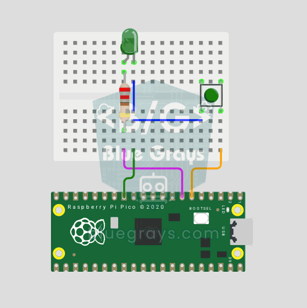
Raspberry Pi Pico Button Debounce: IRQ vs Software Polling
Press a button once, code counts 3-4? That is contact bounce — metal contacts oscillate for microseconds! Compare 2 counting methods side-by-side in Serial: RAW polling (catches bounce, over-counts) vs IRQ + software debounce (accurate). Learn contact bounce physics, software debounce (ticks_diff() > 50ms), Pin.irq() interrupt registration, IRQ_FALLING trigger, ISR handlers, global + ISR safety. LED toggles via IRQ (visual feedback). Serial shows both counters per press

ESP32 LED Control with Pushbutton (Toggle)
Each time the button is pressed the state of the LED changes: if it is on it turns off, if it is off it turns on. Classic toggle pattern. With debounce we clean up the mechanical noise of the pushbutton to ensure a single toggle with a single press.
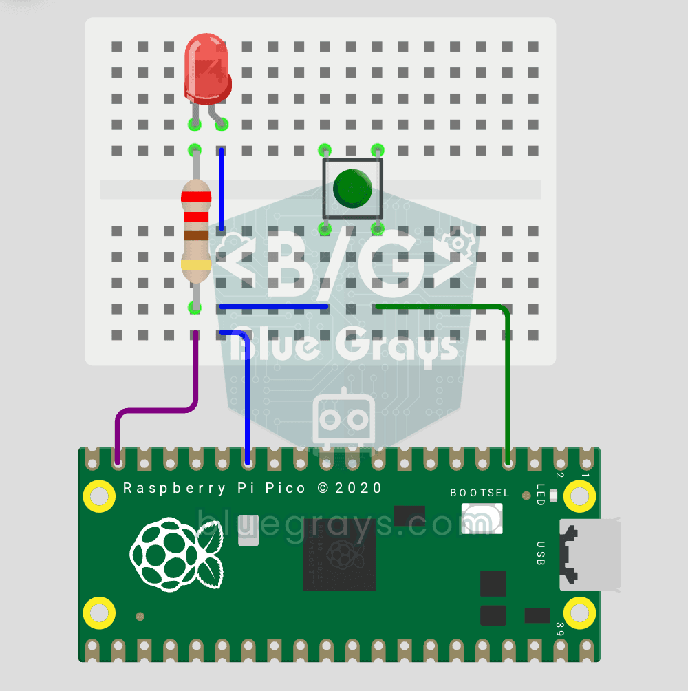
Raspberry Pi Pico Button Toggle LED
Button + LED — next level! Unlike the basic button project, there is no need to hold the button. Press and release → LED on. Press and release again → LED off (toggle). Same circuit (LED GP14, Button GP2), but big code difference. Learn edge detection (capturing the 1→0 falling moment), state tracking, debounce (mechanical bounce filter). MicroPython's led.toggle() swaps state in one line. Foundation of all interactive button projects (mode switcher, IRQ, double-click).
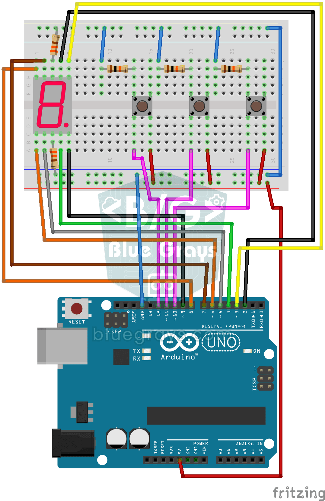
Counter with 7-Segment Display and Buttons
A simple counter with three buttons: press one and the digit on the display goes up by one, press another and it goes down by one, and the third sends it back to zero. The single-digit 7-segment displ
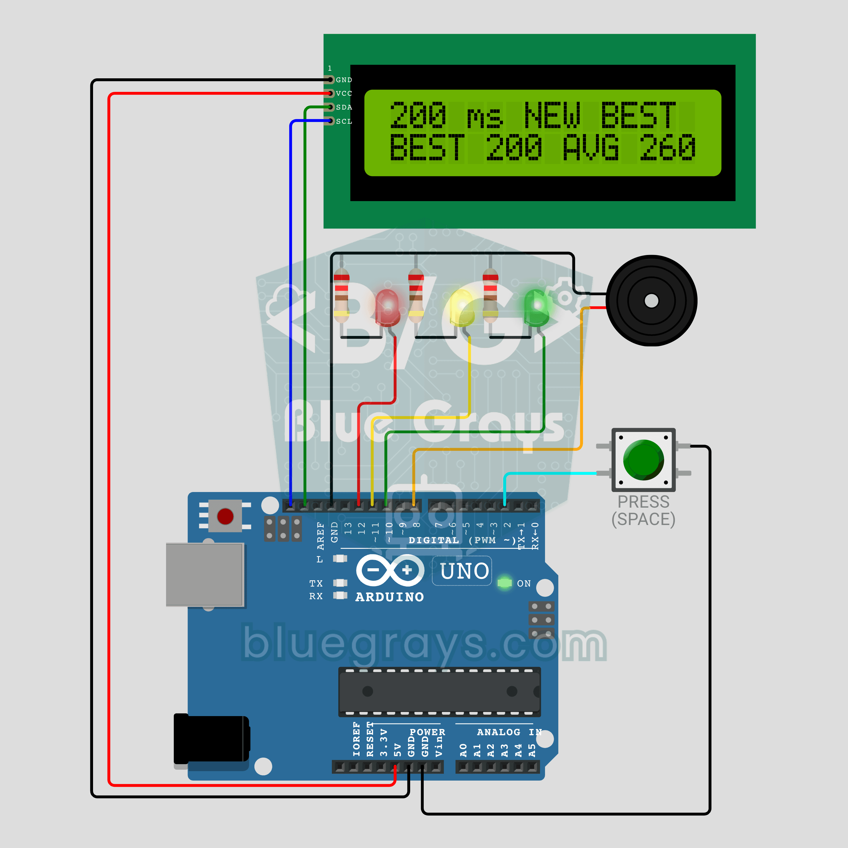
Arduino Reaction Time Test with Sound Cue: Measure Your Reflexes in Milliseconds (LCD + Buzzer + 3 LEDs)
How fast are your reflexes? Press the button: the red LED says get ready, the yellow LED says steady and a random wait of 1.5 to 3.5 seconds begins. The moment the green LED lights up and the buzzer beeps, press again; your reaction time appears on the I2C LCD in milliseconds, with your session best and average below it. Press before green and the screen shows TOO EARLY! with a losing sound. Hold the button for a new player, so everyone races the same wait order.

ESP32 WebSocket Counter (2 Buttons + LCD + Real-Time Web)
In this project, two buttons wired to the ESP32 (GPIO 5 counts up, GPIO 4 counts down) change a counter. The value updates instantly both on a 16x2 I2C LCD and, through the WebSocket support of ESPAsyncWebServer, in every connected browser without reloading the page. Instead of HTTP polling a single persistent connection is used, and the ESP32 sends the new value to everyone with ws.textAll().

Arduino Memory Game (4 LEDs + 4 Buttons + Buzzer)
Do you trust your memory? Four colored LEDs light up in a sequence, each playing its own note, and you repeat the same order by pressing the buttons. Every correct round adds a new color to the sequen