
Reed Switch Arduino Tutorial: Door Sensor, Alarm and Speedometer
How a reed switch works and how to wire it to Arduino: NO/NC types, magnet distance, pull-up and debounce, door alarm, bike speedometer, ESP32 and Pico code.
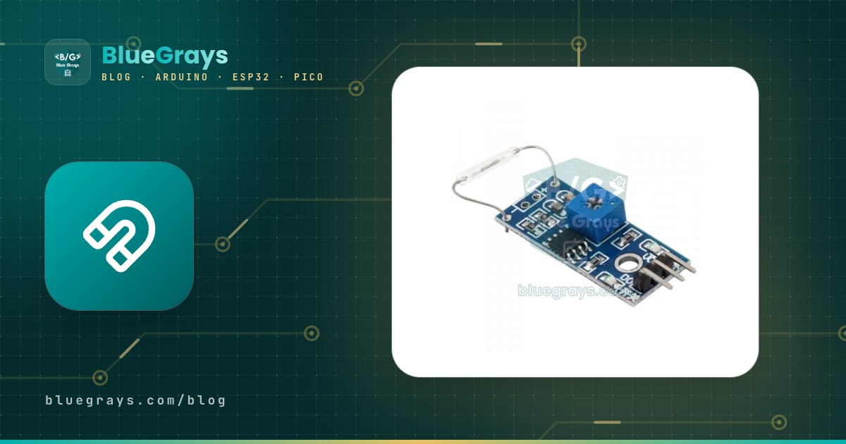
A reed switch (magnetic switch) is a simple sensor that closes a circuit when a magnet pulls two thin metal blades inside a glass tube into contact, and it uses no power at all by itself. On an Arduino you read it just like a button: the contacts close when a magnet is near and open again when it moves away. This tiny glass tube hides inside door and window alarms, bike computers, float level switches and wind gauges.
In this guide you will learn step by step what is inside a reed switch, the NO and NC types, at what distance and orientation the magnet works best, and how to wire it to an Arduino with a pull-up resistor. Then you will fix contact bounce in software, build a door-open alarm and a bike speedometer, send a "door opened" notification to your phone with an ESP32 and run the same circuit on a Raspberry Pi Pico with MicroPython. The last sections compare the reed switch with a Hall sensor and collect the most common mistakes.
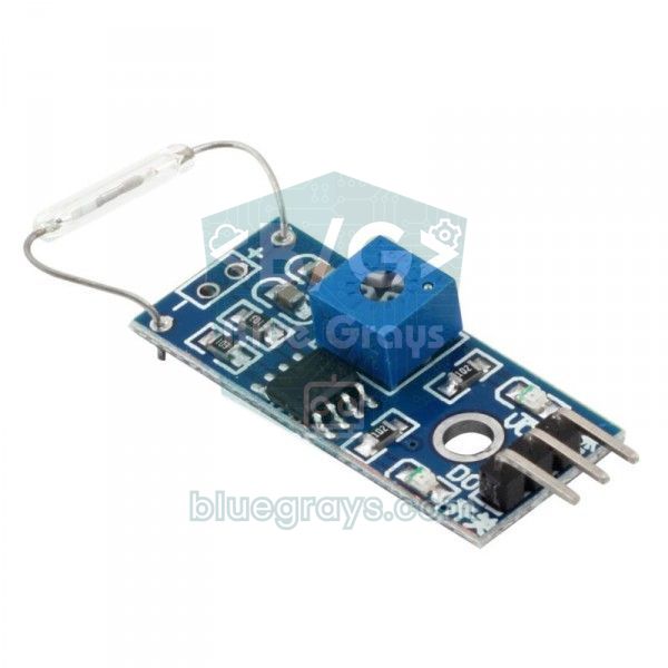
What is a reed switch and how does it work?
The heart of a reed switch is a small glass tube that is either filled with an inert gas such as nitrogen or evacuated. Two flexible nickel-iron blades enter from both ends and overlap in the middle with a very small gap; the word "reed" refers to these blades. Their tips are plated with hard metals such as rhodium or ruthenium, which keeps the contact resistance low and reduces wear. When a magnet comes close, both blades become magnetized, opposite poles form at the overlapping tips and the blades pull each other into contact. When the magnet moves away, the spring force of the blades separates the contacts again. Because the glass protects the contacts from dust, moisture and oxidation, reed switches can operate hundreds of millions of times at low current.
Many sellers call this part a "reed relay", but technically the glass tube on its own is a reed switch. A real reed relay is the same glass tube with a coil wound around it; there, current through the coil closes the contacts instead of a magnet. This article covers the magnet-operated switch and the sensor modules built around it. Its biggest advantage is that it consumes no power: only your own circuit's current flows through it, which makes it ideal for devices that run for months on batteries.
Reed switch specifications
| Property | Typical value (small glass reed) |
|---|---|
| Contact type | Form A (NO, normally open) is the most common |
| Glass body | About 2 mm in diameter, 10–15 mm long |
| Switching power | Up to 10 W |
| Switching voltage | Up to 100–200 V DC |
| Switching current | About 0.5 A |
| Contact resistance | Below 0.1 Ω |
| Operate time | Under 1 ms (including bounce) |
| Sensitivity | 10–40 AT (ampere-turns) |
| Life | 100 million to 1 billion operations at low current |
| Own consumption | None (passive component) |
Sensitivity is given in AT (ampere-turns): the current multiplied by the number of turns needed to close the reed in a standard test coil. The lower the value, the weaker the magnet that can operate it, so it works from farther away. There is also hysteresis: the field needed to close the contacts (pull-in) is stronger than the field needed to keep them closed. For example, a reed that a magnet closes at 15 mm may only open again at around 20 mm. This difference reduces chattering on small vibrations, but your design must make sure the magnet also moves beyond the drop-out distance.
NO, NC and changeover reed types (Form A, B, C)
Reed switches come in three contact arrangements. The labels NO (normally open) and NC (normally closed) always describe the contact state with no magnet present.
| Type | No magnet | Magnet nearby | Leads | Where is it used? |
|---|---|---|---|---|
| Form A (NO) | Open | Closed | 2 | Door sensors, speed counters, most modules |
| Form B (NC) | Closed | Open | 2 | Applications that must close the circuit when the magnet moves away |
| Form C (changeover) | COM–NC closed | COM–NO closed | 3 | Circuits that need both an open and a closed output |
Triggering with a magnet: distance, orientation and sensitivity
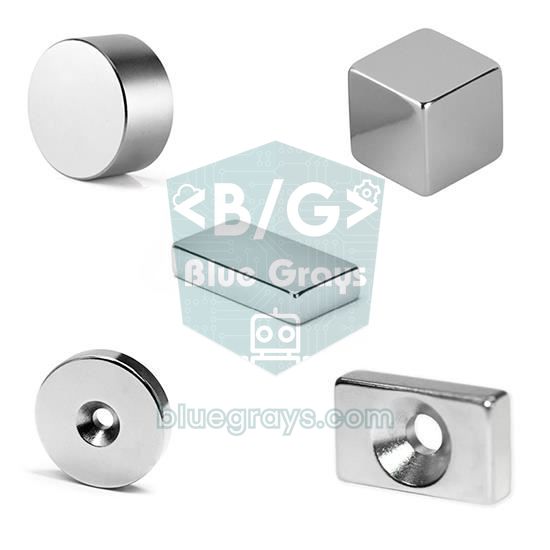
The best way to trigger a reed switch is a small neodymium magnet. A 10×3 mm neodymium disc usually operates a common reed from 10–20 mm; a black ferrite magnet of the same size roughly halves that distance. Ready-made door sensors typically work at 15–25 mm. The distance depends not only on the magnet's strength but also on its orientation: when the magnet's north-south axis is held parallel to the glass tube and brought to its middle, you get a single, clean closure. If the magnet is perpendicular to the tube, it may not trigger at all in the exact middle and instead triggers at two points near the ends. A parallel magnet slid along the tube also creates small extra closing zones on both sides of the main one. As the magnet passes the reed, the contacts can therefore close and open two or three times; this is the most common reason why counting projects register one revolution as two or three.
- Polarity does not matter: A reed reacts the same way to the north and the south pole; flipping the magnet does not change the result.
- Align the magnet with the middle of the tube: In door sensors, the magnet and the reed body should sit side by side and parallel, with the gap as small as possible.
- Steel doors shorten the distance: Iron draws the magnet's field into itself. Raise the sensor and the magnet with a 5–10 mm plastic spacer or use a stronger magnet.
- Measure the distance first: With the Serial Monitor open, move the magnet slowly toward and away from the reed. With the door closed, the magnet should be comfortably within the pull-in distance; once the door opens a little, it should be beyond the drop-out distance.
- Keep it away from strong fields: Speakers, motors and other magnets can close the reed unintentionally; do not mount the reed right next to them.
Reed switch Arduino wiring: why is a pull-up resistor essential?
Because a reed switch behaves like a button, it does not produce a voltage on its own; it only connects or disconnects its two leads. While the contacts are open, the pin is connected to nothing (it floats) and you read random HIGH and LOW values caused by noise. The fix is a pull-up resistor: the pin is pulled to 5 V (or 3.3 V) through a resistor, and the reed goes between the pin and GND. Without a magnet the pin reads HIGH; when the magnet closes the contacts, the pin is tied directly to GND and reads LOW. The Arduino Uno has a 20–50 kΩ internal pull-up resistor, so writing pinMode(pin, INPUT_PULLUP) is enough and no external resistor is needed. For the details of this logic, see the how to connect a button to Arduino guide.
| Connection | Arduino Uno | ESP32 | Raspberry Pi Pico |
|---|---|---|---|
| Reed lead 1 (bare reed) | D2 | GPIO 27 | GP15 (physical pin 20) |
| Reed lead 2 (bare reed) | GND | GND | GND |
| Pull-up | Internal (INPUT_PULLUP) | Internal (INPUT_PULLUP) | Internal (Pin.PULL_UP) |
| Module VCC | 5V | 3V3 | 3V3(OUT) (physical pin 36) |
| Module GND | GND | GND | GND |
| Module DO | D2 | GPIO 27 | GP15 |
| Status LED | D13 (onboard LED) | GPIO 2 (onboard LED) | Onboard LED |
| Active buzzer (+) | D8 | Not used | GP14 |
Step by step first circuit: detecting a magnet
- Connect one lead of the reed switch to the Arduino's D2 pin and the other to GND. A bare reed has no polarity, so the direction of the leads does not matter.
- If you use a module, connect VCC to 5V, GND to GND and the DO output to D2.
- Upload the code below and open the Serial Monitor at 9600 baud.
- Slowly bring the magnet closer while holding it parallel to the glass tube; the onboard LED should light up and "magnet detected" should appear on the screen.
- While moving the magnet away, measure with a ruler at what distance the LED turns off; this is your drop-out distance.
1const byte REED_PIN = 2;             // reed: D2 ile GND arasında / reed between D2 and GND
2const byte LED_PIN = 13;             // karttaki LED / onboard LED
3
4void setup() {
5  Serial.begin(9600);
6  pinMode(REED_PIN, INPUT_PULLUP);   // dahili pull-up: mıknatıs yokken HIGH / internal pull-up: HIGH without a magnet
7  pinMode(LED_PIN, OUTPUT);
8}
9
10void loop() {
11  if (digitalRead(REED_PIN) == LOW) {       // kontak kapalı: mıknatıs yakında / contacts closed: magnet nearby
12    digitalWrite(LED_PIN, HIGH);
13    Serial.println(F("Miknatis var / magnet detected"));
14  } else {                                  // kontak açık: mıknatıs uzakta / contacts open: magnet away
15    digitalWrite(LED_PIN, LOW);
16    Serial.println(F("Miknatis yok / no magnet"));
17  }
18  delay(200);
19}
The only thing to watch in the code is the inverted logic: because you use INPUT_PULLUP, you read LOW when the magnet is present and HIGH when it is not. On 3-pin LM393 modules the output also usually goes LOW when the magnet approaches and the DO LED on the board lights up; since this can vary from model to model, check your own module in the Serial Monitor first. The potentiometer on the module sets the comparator threshold; because the reed already works as on/off, it has little effect on the detection distance and leaving it in the middle is usually fine. Mini modules such as the KY-021 have no comparator; the board only carries the reed and a 10 kΩ resistor.
Debounce: contact bounce and vibration
Like any mechanical contact, a reed switch can bounce a few times as it closes. In a reed this bounce is very short, usually under 1 ms, but that is not the real problem. If the magnet moves slowly at the edge of the pull-in distance, or the door rattles in the wind, the contacts can open and close many times within a second. That is why a system that sends a door-opened notification can fire five messages for a single opening. The fix is to wait until the state stays unchanged for a certain time instead of accepting every change immediately. For a door sensor 50–100 ms is enough; for a speed counter, using the shortest physically possible time between two pulses as a lockout time works well.
If you want a hardware solution, place a 100 nF capacitor between the pin and GND. Together with a 10 kΩ pull-up this gives a time constant of τ = R × C = 10 kΩ × 100 nF = 1 ms, which smooths out very short bounces. You can try other resistor and capacitor pairs with the RC time constant calculator. With the internal pull-up the resistance is 20–50 kΩ, so the time grows to 2–5 ms. On door sensors with several meters of cable, an external 4.7–10 kΩ pull-up plus this capacitor also protects against noise.
Door and window open sensor with an alarm project
The most common reed project is a door sensor. Mount the magnet on the moving door leaf and the reed on the frame; when the door is closed they sit side by side, the contacts are closed and the pin reads LOW. When the door opens, the magnet moves away and the pin goes HIGH. This arrangement has a nice side effect: if someone cuts the sensor cable, the pin also goes HIGH and the system sees it as "door opened". This is why alarm systems use closed-loop wiring. The code below counts every opening, measures how long the door stays open and beeps the buzzer intermittently if the door is left open for more than 30 seconds; it is perfect for a fridge or freezer door.
1const byte REED_PIN = 2;                  // reed: D2 ile GND arası / reed between D2 and GND
2const byte BUZZER_PIN = 8;                // aktif buzzer artı ucu / active buzzer positive leg
3const byte LED_PIN = 13;                  // karttaki LED / onboard LED
4const unsigned long STABLE_MS = 50;       // debounce: 50 ms değişmeden kalmalı / debounce: must hold for 50 ms
5const unsigned long OPEN_LIMIT = 30000;   // 30 sn'den uzun açık kalırsa alarm / alarm if open longer than 30 s
6
7bool doorOpen = false;                    // onaylanmış durum / confirmed state
8bool lastReading = false;                 // son ham okuma / last raw reading
9unsigned long lastChange = 0;             // ham okumanın son değiştiği an / when the raw reading last changed
10unsigned long openedAt = 0;               // kapının açıldığı an / when the door was opened
11unsigned int openCount = 0;               // toplam açılış / total openings
12
13void setup() {
14  Serial.begin(9600);
15  pinMode(REED_PIN, INPUT_PULLUP);
16  pinMode(BUZZER_PIN, OUTPUT);
17  pinMode(LED_PIN, OUTPUT);
18  doorOpen = (digitalRead(REED_PIN) == HIGH);   // açılıştaki durumu al / take the state at boot
19  lastReading = doorOpen;
20}
21
22void loop() {
23  unsigned long now = millis();
24  bool reading = (digitalRead(REED_PIN) == HIGH);   // HIGH: mıknatıs uzak, kapı açık / HIGH: magnet away, door open
25
26  if (reading != lastReading) {           // ham değer değişti, sayacı yeniden başlat / raw value changed, restart the timer
27    lastReading = reading;
28    lastChange = now;
29  }
30
31  if (reading != doorOpen && now - lastChange >= STABLE_MS) {   // 50 ms kararlı: gerçek değişim / stable for 50 ms: real change
32    doorOpen = reading;
33    if (doorOpen) {
34      openedAt = now;
35      openCount++;
36      Serial.print(F("Kapi acildi / door opened, sayac / count: "));
37      Serial.println(openCount);
38    } else {
39      Serial.print(F("Kapi kapandi / door closed, sure / duration (s): "));
40      Serial.println((now - openedAt) / 1000);
41    }
42  }
43
44  digitalWrite(LED_PIN, doorOpen ? HIGH : LOW);     // LED kapı açıkken yanar / LED is on while the door is open
45
46  // Uzun süre açık kalırsa çeyrek saniyede bir öt / beep every quarter second if left open too long
47  bool alarm = doorOpen && (now - openedAt > OPEN_LIMIT);
48  digitalWrite(BUZZER_PIN, (alarm && (now / 250) % 2) ? HIGH : LOW);
49}
Because the code does not use delay(), the loop checks the pin continuously and never misses an opening; we explain this technique in detail in the millis vs delay article. Every time the raw reading changes, the lastChange time is reset, and the doorOpen state only changes if the value stays the same for 50 ms. The buzzer part divides millis() by 250 to switch on and off every quarter second. To turn it into a real alarm, you can arm and disarm it with a password keypad and add a PIR motion sensor inside the room. For a more complete setup, take a look at the Arduino alarm system article.
Bike speedometer: counting revolutions with a reed switch
Most bike computers consist of a reed switch and a small magnet clipped onto a spoke. Every time the wheel turns, the magnet passes the reed on the fork once and produces a pulse. Measure the time between two pulses and you get the speed; count the pulses and you get the distance: speed (km/h) = circumference (mm) / time (ms) × 3.6. Here mm/ms is exactly m/s, and multiplying by 3.6 converts it to km/h. For example, on a 700x25C wheel with a 2105 mm circumference, 253 ms between two pulses means 2105 / 253 × 3.6 ≈ 30 km/h. The most accurate way to find the circumference is to roll the wheel exactly one turn with the valve at the bottom and measure the distance between the two marks on the ground.
| Tire size | Approximate circumference | Time per revolution at 30 km/h |
|---|---|---|
| 20x1.75 (BMX, kids' bike) | 1515 mm | 182 ms |
| 26x2.1 (mountain bike) | 2068 mm | 248 ms |
| 29x2.1 (mountain bike) | 2288 mm | 275 ms |
| 700x25C (road bike) | 2105 mm | 253 ms |
| 700x28C (city, gravel) | 2136 mm | 256 ms |
1const byte REED_PIN = 2;                  // kesme pini D2 (INT0) / interrupt pin D2 (INT0)
2const float WHEEL_MM = 2105.0;            // 700x25C tekerlek çevresi (mm) / 700x25C wheel circumference (mm)
3const unsigned long LOCKOUT_MS = 80;      // daha sık darbe imkânsız (~95 km/sa) / faster pulses are impossible (~95 km/h)
4const unsigned long TIMEOUT_MS = 3000;    // 3 sn darbe yoksa hız 0 / no pulse for 3 s means speed 0
5
6volatile unsigned long lastPulseMs = 0;   // son geçerli darbe zamanı / time of the last valid pulse
7volatile unsigned long periodMs = 0;      // son iki darbe arası süre / time between the last two pulses
8volatile unsigned long revCount = 0;      // toplam tur / total revolutions
9
10void onMagnet() {                         // ISR: kısa ve hızlı / ISR: short and fast
11  unsigned long now = millis();
12  unsigned long dt = now - lastPulseMs;
13  if (dt < LOCKOUT_MS) return;            // sıçrama ya da çift darbe: yok say / bounce or double pulse: ignore
14  periodMs = (dt < TIMEOUT_MS) ? dt : 0;  // uzun duraklamadan sonraki ilk darbe hız vermez / first pulse after a stop gives no speed
15  lastPulseMs = now;
16  revCount++;
17}
18
19void setup() {
20  Serial.begin(9600);
21  pinMode(REED_PIN, INPUT_PULLUP);
22  attachInterrupt(digitalPinToInterrupt(REED_PIN), onMagnet, FALLING);   // mıknatıs gelince HIGH->LOW / HIGH->LOW when the magnet arrives
23}
24
25void loop() {
26  static unsigned long lastPrint = 0;
27  if (millis() - lastPrint < 500) return; // saniyede 2 kez yaz / print twice per second
28  lastPrint = millis();
29
30  noInterrupts();                         // çok baytlı değerleri güvenle kopyala / copy multi-byte values safely
31  unsigned long period = periodMs;
32  unsigned long last = lastPulseMs;
33  unsigned long revs = revCount;
34  interrupts();
35
36  float speedKmh = 0;
37  if (period > 0 && millis() - last < TIMEOUT_MS) {
38    speedKmh = WHEEL_MM / period * 3.6;   // mm/ms = m/s; 3,6 ile çarp = km/sa / multiply by 3.6 = km/h
39  }
40  float distanceKm = revs * WHEEL_MM / 1000000.0;   // tur x çevre / revolutions x circumference
41
42  Serial.print(F("Hiz / speed: "));
43  Serial.print(speedKmh, 1);
44  Serial.print(F(" km/h   Mesafe / distance: "));
45  Serial.print(distanceKm, 3);
46  Serial.println(F(" km"));
47}
Because the pulse is captured with attachInterrupt, no revolution is missed no matter how busy loop() is; on the Arduino Uno only pins D2 and D3 provide this kind of interrupt. The LOCKOUT_MS value is very important: 80 ms corresponds to a top speed of about 95 km/h on a 2105 mm wheel (2105 / 80 × 3.6). Pulses that arrive closer together are physically impossible, so they are ignored as bounce, side closing zones of the magnet or the contact bouncing as it opens. If no pulse arrives for 3 seconds, the speed is taken as zero. With the same structure you can measure the speed of a motor or a wheel in revolutions per minute: RPM = 60000 / time (ms). For more on interrupts, see the Arduino interrupt guide; to show the speed on a handlebar display, combine the code with an OLED display.
Reed switch or Hall sensor?
The second way to detect a magnet is a Hall sensor. A Hall sensor turns the magnetic field into an electrical signal inside a semiconductor chip; it has no moving parts but needs a power supply to work. The short rule: for a door or window sensor that runs on batteries for a long time and triggers rarely, choose a reed; for fast and continuous counting, such as a motor, a fan or a water flow sensor spinning dozens of times per second, a Hall sensor is the better choice.
| Property | Reed switch | Hall sensor (A3144, US1881, 49E) |
|---|---|---|
| How it works | Mechanical contact, closed by a magnet | Semiconductor, turns the field into an electrical signal |
| Power supply | Not needed, uses no power itself | Required (a few mA) |
| Switching speed | Hundreds of times per second | Up to tens of thousands of Hz |
| Contact bounce | Yes (under 1 ms) | None |
| Life | Mechanical wear, 100 million – 1 billion operations | No moving parts, no wear |
| Pole detection | No, reacts to both poles | Depending on the model: unipolar, bipolar or latching |
| Analog measurement | No, only open or closed | Linear models (49E) measure field strength |
| Load switching | Can switch small AC/DC loads directly | Signal output only |
| Durability | Glass tube is sensitive to impact and bending | Plastic package, resistant to shock |
Door-opened notification with ESP32 (Telegram)
Thanks to the ESP32's Wi-Fi, the door sensor can send a message to your phone the moment the door opens. For this you need to create a bot with BotFather in Telegram, get its token and your own chat ID, and install the UniversalTelegramBot and ArduinoJson libraries in the Arduino IDE; we explain these steps in detail in the ESP32 Telegram bot article. Connect one lead of the reed to GPIO 27 and the other to GND. The code sends a message when the door opens and closes, reminds you if the door stays open for more than 5 minutes and, if Wi-Fi is down at that moment, retries the message 10 seconds later.
1#include <WiFi.h>
2#include <WiFiClientSecure.h>
3#include <UniversalTelegramBot.h>
4#include <ArduinoJson.h>
5
6const char* WIFI_SSID = "AgAdi";          // Wi-Fi adın (yalnız 2,4 GHz) / your Wi-Fi name (2.4 GHz only)
7const char* WIFI_PASS = "Sifre123";       // Wi-Fi şifren / your Wi-Fi password
8#define BOT_TOKEN "1234567890:AAExxxxxxxxxxxxxxxxxxxxxxxxxxxxxxxx"   // BotFather'ın verdiği token / token from BotFather
9#define CHAT_ID   "123456789"             // bildirimin gideceği ID / the ID that receives alerts
10
11const int REED_PIN = 27;                  // reed: GPIO 27 ile GND arası / reed between GPIO 27 and GND
12const int LED_PIN  = 2;                   // çoğu DevKit'te dahili LED / onboard LED on most DevKits
13const unsigned long STABLE_MS = 100;      // değişim 100 ms sürmeli / a change must last 100 ms
14const unsigned long REMIND_MS = 300000;   // 5 dk açık kalırsa hatırlat / remind after 5 min open
15const unsigned long RETRY_MS  = 10000;    // gönderilemeyen mesajı 10 sn sonra dene / retry a failed message after 10 s
16
17WiFiClientSecure client;                  // şifreli (HTTPS) bağlantı / encrypted (HTTPS) connection
18UniversalTelegramBot bot(BOT_TOKEN, client);
19
20bool doorOpen = false;                    // onaylanmış kapı durumu / confirmed door state
21bool lastRaw = false;                     // son ham okuma / last raw reading
22unsigned long lastChange = 0;
23unsigned long openedAt = 0;
24bool reminded = false;
25String pending = "";                      // gönderilmeyi bekleyen mesaj / message waiting to be sent
26unsigned long lastTry = 0;
27
28void notify(const String& text) {
29  Serial.println(text);
30  if (WiFi.status() == WL_CONNECTED && bot.sendMessage(CHAT_ID, text)) {
31    pending = "";                         // gönderildi / sent
32  } else {
33    pending = text;                       // Wi-Fi yoksa sonra dene / no Wi-Fi: try again later
34    lastTry = millis();
35  }
36}
37
38void setup() {
39  Serial.begin(115200);
40  pinMode(REED_PIN, INPUT_PULLUP);        // dahili pull-up; GPIO 34-39'da yoktur / internal pull-up; GPIO 34-39 have none
41  pinMode(LED_PIN, OUTPUT);
42
43  WiFi.mode(WIFI_STA);
44  WiFi.begin(WIFI_SSID, WIFI_PASS);
45  Serial.print("Wi-Fi'ye baglaniyor / connecting to Wi-Fi");
46  while (WiFi.status() != WL_CONNECTED) {
47    delay(500);
48    Serial.print(".");
49  }
50  Serial.println();
51  Serial.println(WiFi.localIP());
52  client.setCACert(TELEGRAM_CERTIFICATE_ROOT);   // api.telegram.org kök sertifikası / root certificate of api.telegram.org
53
54  doorOpen = (digitalRead(REED_PIN) == HIGH);    // HIGH = mıknatıs uzak = kapı açık / HIGH = magnet away = door open
55  lastRaw = doorOpen;
56  openedAt = millis();
57  digitalWrite(LED_PIN, doorOpen ? HIGH : LOW);
58  notify(String("Kapı sensörü hazır, kapı ") + (doorOpen ? "AÇIK" : "KAPALI") + " / door sensor ready");
59}
60
61void loop() {
62  unsigned long now = millis();
63  bool raw = (digitalRead(REED_PIN) == HIGH);
64
65  if (raw != lastRaw) {                   // ham değer değişti / raw value changed
66    lastRaw = raw;
67    lastChange = now;
68  }
69
70  if (raw != doorOpen && now - lastChange >= STABLE_MS) {   // kararlı değişim / stable change
71    doorOpen = raw;
72    digitalWrite(LED_PIN, doorOpen ? HIGH : LOW);
73    if (doorOpen) {
74      openedAt = now;
75      reminded = false;
76      notify("Kapı AÇILDI! / door OPENED!");
77    } else {
78      unsigned long sec = (now - openedAt) / 1000;
79      notify("Kapı kapandı / door closed (" + String(sec) + " sn)");
80    }
81  }
82
83  if (doorOpen && !reminded && now - openedAt > REMIND_MS) {   // açık unutuldu / left open
84    reminded = true;
85    notify("Kapı 5 dakikadır açık! / door open for 5 minutes!");
86  }
87
88  if (pending.length() > 0 && now - lastTry > RETRY_MS) {      // bekleyen mesajı yeniden dene / retry the pending message
89    String msg = pending;
90    notify(msg);
91  }
92}
Sending a message to Telegram can take 1–2 seconds and the loop waits during that time; however, because the state machine reads the pin again after sending, the last state of the door is never lost. If you want to run the sensor on batteries, put the ESP32 into deep sleep and use esp_sleep_enable_ext0_wakeup(GPIO_NUM_27, 1) so it wakes up when the door opens and the pin goes HIGH. If you set the wake-up level to the opposite of the pin's current state before going to sleep, the board wakes up both on opening and on closing. In this case, also account for the current through the pull-up resistor: while the door is closed the reed is closed, so 3.3 V / 10 kΩ = 330 µA flows continuously through a 10 kΩ resistor; with 100 kΩ the current drops to 33 µA. In deep sleep, an external resistor is the safest choice instead of the internal pull-up. You can estimate battery life with the battery life calculator.
Reed switch with Raspberry Pi Pico and MicroPython
Reading a reed switch on the Raspberry Pi Pico takes only a few lines of MicroPython. Connect the reed between GP15 and GND, then the active buzzer's positive lead to GP14 and its negative lead to GND. Because the Pico runs at 3.3 V, always power a module from the 3V3(OUT) pin; if you power the module with 5 V, its DO output rises to 5 V and can damage the Pico's input. The Pico's internal pull-up is around 50–80 kΩ, which is enough for short cables.
1from machine import Pin
2import time
3
4reed = Pin(15, Pin.IN, Pin.PULL_UP)   # reed: GP15 ile GND arası / reed between GP15 and GND
5buzzer = Pin(14, Pin.OUT)             # aktif buzzer artı ucu / active buzzer positive leg
6led = Pin("LED", Pin.OUT)             # dahili LED (Pico ve Pico W) / onboard LED (Pico and Pico W)
7
8STABLE_MS = 50                        # debounce süresi / debounce time
9door_open = reed.value() == 1         # 1 = mıknatıs uzak = kapı açık / 1 = magnet away = door open
10last_raw = door_open
11last_change = time.ticks_ms()
12open_count = 0
13led.value(door_open)
14
15while True:
16    raw = reed.value() == 1
17    now = time.ticks_ms()
18    if raw != last_raw:                       # ham değer değişti / raw value changed
19        last_raw = raw
20        last_change = now
21    if raw != door_open and time.ticks_diff(now, last_change) >= STABLE_MS:
22        door_open = raw                       # 50 ms kararlı: gerçek değişim / stable for 50 ms: real change
23        led.value(door_open)
24        if door_open:
25            open_count += 1
26            print("Kapi acildi / door opened:", open_count)
27            buzzer.on()
28            time.sleep_ms(100)                # kısa bip / short beep
29            buzzer.off()
30        else:
31            print("Kapi kapandi / door closed")
32    time.sleep_ms(5)
The code builds the same debounce logic as on the Arduino using time.ticks_ms() and time.ticks_diff(); ticks_diff returns the correct difference even when the counter wraps around. For pulses that must not be missed, such as a speed counter, you can use an interrupt with reed.irq(trigger=Pin.IRQ_FALLING, handler=...). If you have a Pico W, you can add the Pico W example from the Telegram bot article to this code to send the same event to your phone over Wi-Fi. If you are using the Pico for the first time, start with the what is the Raspberry Pi Pico guide.
Reed switch project ideas
- Wireless door and window sensor: Report every opening in your home to your phone with an ESP32 or send it to Home Assistant via MQTT.
- Fridge door reminder: Beep intermittently when the door stays open for more than 30 seconds.
- Bike computer: Show current speed, total distance and average speed on a display.
- Wind and rain gauge: In weather stations, the cup anemometer produces one reed pulse per revolution and the tipping-bucket rain gauge one pulse per tip.
- Float level switch: The magnet inside the float opens and closes the reed in the stem to report that the tank is full; details in the water level sensor article.
- Secret drawer lock: Build a solenoid lock that opens only when a magnet is held at the right spot.
- Mailbox notification: A reed on the flap wakes the ESP32 from deep sleep when mail arrives.
Common mistakes and how to fix them
- The pin reads random values: There is no pull-up. Set pinMode to INPUT_PULLUP or add an external 10 kΩ pull-up resistor.
- The logic is inverted: With a pull-up, the pin reads LOW when the magnet is present; your code may expect HIGH, or your sensor is an NC type. Check it with a multimeter.
- Several counts for one opening: There is no debounce, or the magnet passes through the side closing zones. Add a stable time and align the magnet parallel to the tube.
- The reed never closes: The magnet is weak, the distance is too large, the magnet is perpendicular to the middle of the tube or a steel door absorbs the field. Use a stronger neodymium magnet and a plastic spacer.
- The reed stays closed all the time: The contacts may have welded because of excess current or a capacitive load. Never drive a motor, lamp or relay coil directly with a reed; switch loads with a relay module or a transistor.
- The glass tube cracked: The leads were bent too close to the body. Hold the lead with pliers, bend it at least 2–3 mm away from the glass and finish soldering quickly.
- False alarms on long cables: The internal pull-up is too weak. Use an external 4.7–10 kΩ pull-up, a 100 nF capacitor on the pin and twisted-pair cable.
A reed switch is a cheap and extremely reliable sensor that detects a magnet without using any power; with the right magnet orientation, a pull-up resistor and a few lines of debounce code, it works trouble-free for years. In the BlueGrays app you can find the Reed Switch Value Reading and Reed Switch Door Sensor projects, as well as projects such as the ESP32 motion alarm and the alarm system with Telegram notifications, with step-by-step circuit diagrams and code.
Frequently asked questions
How does a reed switch work?
A reed switch consists of two nickel-iron blades inside a glass tube. When a magnet comes near, the blades become magnetized, attract each other and the contacts close; when the magnet moves away, their spring force separates them. It uses no power itself and is read on an Arduino just like a button.
Is a reed switch normally open or normally closed?
The most common reed switches are NO (normally open, Form A): open without a magnet and closed when a magnet comes near. NC (Form B) and three-lead changeover (Form C) versions also exist. On alarm door contacts, however, the "NC" label means the circuit is closed while the door is shut and the magnet is next to it, so testing with a multimeter is the safest way.
How far away can a magnet trigger a reed switch?
It depends on the magnet's strength and the reed's sensitivity. A small neodymium magnet usually triggers common reeds from 1–2 cm, and ready-made door sensors work at 15–25 mm; with ferrite magnets the distance is roughly halved. Holding the magnet parallel to the tube and keeping it away from steel surfaces increases the distance.
Does a reed switch need a resistor?
The Arduino input needs a pull-up or pull-down resistor; otherwise the pin floats and reads random values while the contacts are open. Since the Arduino, ESP32 and Pico have internal pull-ups that you can enable with INPUT_PULLUP or Pin.PULL_UP, an external resistor is usually not needed. On long cables an external 4.7–10 kΩ resistor gives more stable results.
What is the difference between a reed switch and a Hall effect sensor?
A reed switch is a mechanical contact; it needs no power and can switch small loads directly, but it bounces and its glass tube is fragile. A Hall sensor is a semiconductor; it needs a power supply, does not bounce and is much faster. A reed is preferred for battery-powered door sensors, a Hall sensor for fast revolution counting.
Can a reed switch switch a mains lamp?
Small glass reed switches can usually handle at most 10 W of switching power, so switching a mains lamp or motor directly will weld the contacts and is dangerous. Connect the reed to the Arduino only as a signal, control the mains load with a relay module and always follow safety rules when working with mains voltage.
Projects to build after reading this
See all projects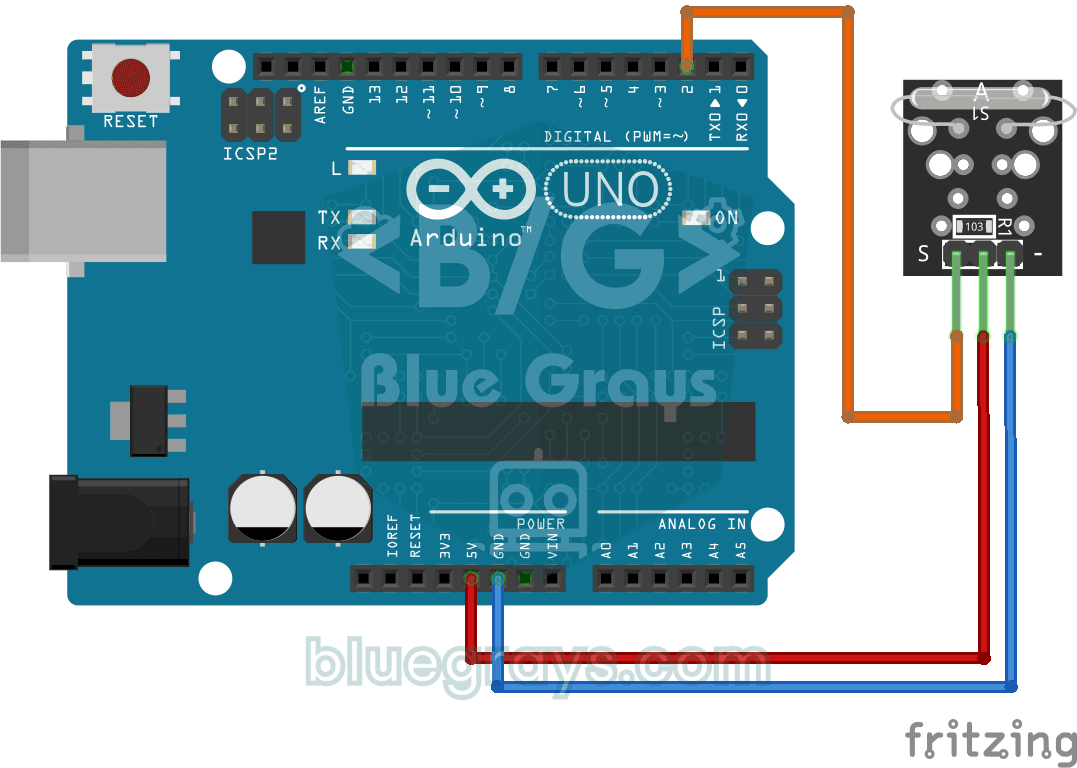
Reading a Reed Switch
Ever wondered about the magnetic switch inside door and window alarms? When a magnet comes near the reed relay module, the tiny switch inside it closes; the Arduino reads it once a second and prints 0
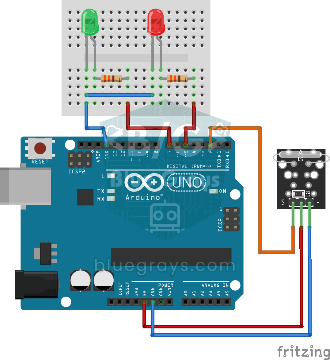
Reed Switch Door Sensor
Tell whether your door is open or closed just by looking at a light. You attach a small magnet to the door and a magnet-sensing switch to the frame; when the door is closed they sit side by side and t

LED Control with a Push Button (Push)
Just like a doorbell: the light stays on as long as you press, and goes off when you let go. The Arduino keeps listening to the button; while it's pressed the LED is on, and the moment you lift your f

ESP32 LED Control with Push Button (Push)
The LED lights up when the button is pressed and turns off when released. Shows how the ESP32's digital input pin and internal pull-up resistor are used. The INPUT_PULLUP mode eliminates the need for an external resistor.
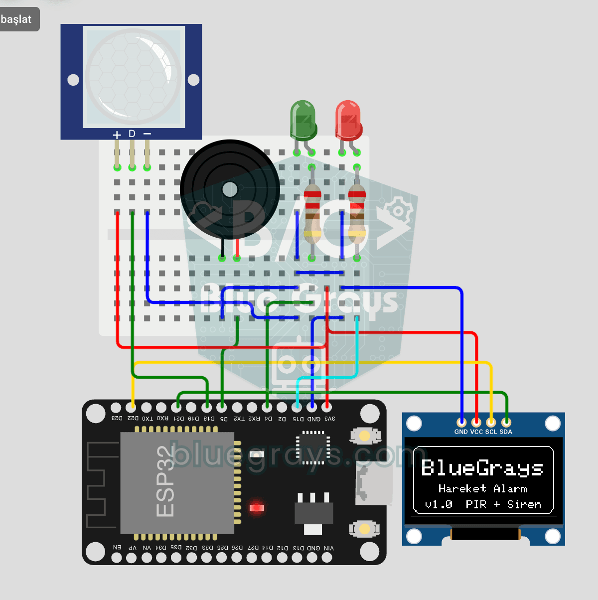
ESP32 Motion Alarm System (PIR + Buzzer + LED + Telegram)
A smart security alarm system that activates the buzzer and LED when the PIR sensor detects motion, while simultaneously sending an instant notification to the owner via Telegram. It includes a 30-second cooldown to limit the frequency of repeated alarms; this mechanism does not validate PIR detections or eliminate false triggers. Suitable for home security, garage monitoring, warehouses, or workrooms. With ESP32-CAM, photo notifications can be added; with the classic ESP32 DevKit V1, text notif
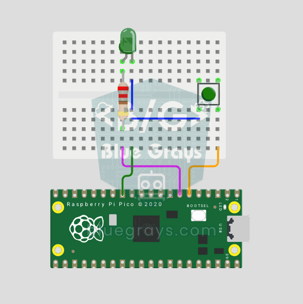
Raspberry Pi Pico Button Debounce: IRQ vs Software Polling
Press a button once, code counts 3-4? That is contact bounce — metal contacts oscillate for microseconds! Compare 2 counting methods side-by-side in Serial: RAW polling (catches bounce, over-counts) vs IRQ + software debounce (accurate). Learn contact bounce physics, software debounce (ticks_diff() > 50ms), Pin.irq() interrupt registration, IRQ_FALLING trigger, ISR handlers, global + ISR safety. LED toggles via IRQ (visual feedback). Serial shows both counters per press
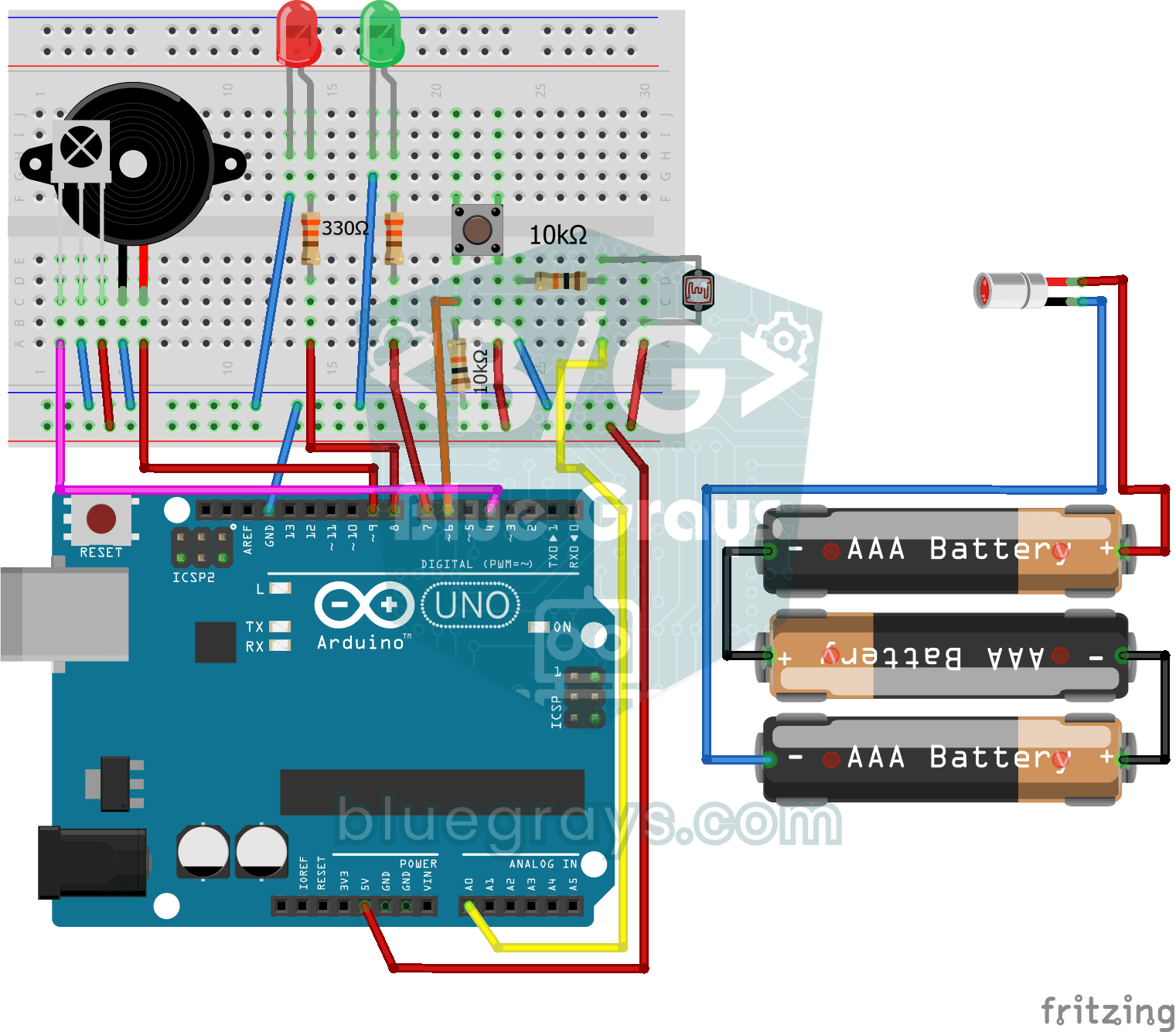
Laser Security System
Just like the laser heist scenes in films: a laser beam shines on a light sensor, and the moment someone steps in and breaks the beam, the red LED lights up and the buzzer starts sounding. The alarm d