
Is My Arduino Dead? Symptoms, Diagnosis and How to Revive It
Is your Arduino dead? No ON LED, hot chip or missing port: test Vin, polyfuse, regulator, USB chip and pins, reburn the bootloader and swap the ATmega328P.
"Is my Arduino dead?" is a question almost every electronics hobbyist asks one day: a wire touches the wrong place, a motor gets connected, and the board suddenly goes quiet. The good news is that in most of these cases the whole board isn't dead. An Arduino Uno is made of several separate sections: the USB connection and its fuse, the voltage regulator, the USB-to-serial converter chip and the main microcontroller, the ATmega328P. When one of them fails, the others often survive, and with the right diagnosis saving the board can sometimes be a two-minute job.
In this guide you'll learn to read the symptoms correctly and to isolate the board step by step to find which section has failed. We'll go through powering from the Vin input, checking the polyfuse and regulator with a multimeter, finding a hot chip, testing the USB chip with a loopback test and two Arduino sketches that test the pins one by one. Then we'll reburn a corrupted bootloader with a second Arduino, swap the ATmega328P if needed and sum up the rules to follow so you never fry a board again. We cover the software side of upload errors separately in Arduino won't upload.
Is your Arduino dead? First symptoms and what they mean
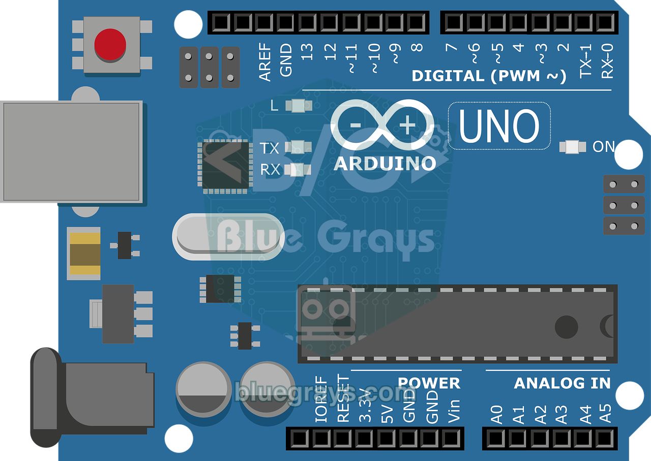
Before you start diagnosing, listen to what the board is telling you. The green ON LED shows whether the 5 V rail has power, the L LED (D13) shows whether the microcontroller and bootloader are running, and the TX/RX LEDs show whether the USB-to-serial chip is passing data. The table below sums up the most common symptoms and where to look first.
| Symptom | Likely fault | First step |
|---|---|---|
| The ON LED doesn't light at all | Short on the 5 V rail, tripped polyfuse, dead regulator or a bad cable | Remove everything, try another cable and power via Vin |
| The ON LED lights, but the board gets very hot | A chip has shorted internally | Unplug at once and find the hot chip |
| The computer doesn't see the board | Charge-only cable, missing driver or dead USB chip | Try another cable, then do the loopback test |
| The port appears, but uploads fail | Corrupted bootloader, a module on D0/D1 or a damaged ATmega328P | Check whether the L LED blinks on reset |
| Code runs, but one pin doesn't respond | That pin was burned by overcurrent or overvoltage | Run the pin test sketches |
| The board resets at random | Weak supply, motor noise or an overheating regulator | Power the loads from a separate supply |
Step 1: First check with your eyes, nose and a cable
- Inspect the board under good light: you're looking for a darkened or bulging chip, a cracked package, melted solder or a charred trace. Look especially around the regulator, the polyfuse and the USB chip.
- Smell the board. Burnt electronics leave a sharp, familiar smell, usually strongest around the failed part.
- Check the underside of the board. A metal desk, a stray piece of wire or conductive foam can bridge the board's solder joints and cause a short.
- Try another USB cable and another USB port. Some cheap cables only have power wires and can't carry data; this is the most common cause of what looks like a dead board.
- Note whether the computer makes its USB connect sound when you plug the board in and whether the ON LED lights; the next steps depend on these two observations.
The Arduino Uno's power path: which part feeds what?
The fastest way to find a fault is to know the path the current takes on the board. The 5 V from USB first passes through a 500 mA polyfuse (a self-resetting fuse), then through a small P-channel MOSFET, and reaches the 5 V rail. The voltage from the DC jack first passes through a diode that protects against reverse polarity, reaches the VIN line and is dropped to 5 V by the NCP1117 regulator. When VIN rises above about 6.6 V, a comparator switches off the MOSFET on the USB side, so the two sources never fight each other. The 3.3 V is produced from the 5 V rail by a small LP2985 regulator. The ON LED, the USB-to-serial chip (an ATmega16U2 on original boards, usually a CH340 on clones) and the ATmega328P are all powered from this 5 V rail.
| Part | Job | What happens when it fails? |
|---|---|---|
| Polyfuse (500 mA) | Protects USB against overcurrent | ON LED off on USB, on with Vin |
| Reverse polarity diode | Protects the DC jack against reversed polarity | ON LED off on the DC jack, on with USB |
| NCP1117 5 V regulator | Drops VIN to 5 V | No 5 V from the DC jack, or a high voltage on the 5 V rail |
| LP2985 3.3 V regulator | Feeds the 3V3 pin (50 mA max) | No voltage on the 3V3 pin |
| ATmega16U2 or CH340 | USB-to-serial converter | The computer doesn't see the port, or no data gets through |
| ATmega328P | The microcontroller that runs your code | Uploads fail, the L LED doesn't blink on reset, pins don't work |
Step 2: If the ON LED is off, test with USB and with Vin
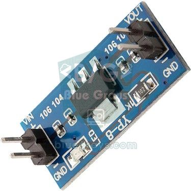
Power the board once from USB and once from a 9 V adapter on the DC jack (or 7–12 V on the Vin pin), and watch the ON LED each time. Since the 5 V rail is what the two paths have in common, this simple comparison narrows the fault down a lot. If the polyfuse has tripped from overcurrent, leave the board unpowered for a few minutes so it can recover by itself; if the short is still there, it will trip again when you plug it back in. We cover battery and adapter options in detail in powering an Arduino from batteries.
| ON LED on USB | ON LED on DC jack / Vin | Meaning |
|---|---|---|
| Off | On | USB side: cable, USB socket, polyfuse or the USB MOSFET |
| On | Off | Jack side: adapter, reverse polarity diode or the NCP1117 regulator |
| Off | Off | Short on the 5 V rail (a chip gets hot) or both paths damaged |
| On | On | Power section is fine; the problem is the USB chip, bootloader or ATmega328P |
Step 3: Checking for shorts, the polyfuse and the regulator with a multimeter
- Short test (board unpowered): Set the multimeter to resistance or continuity and touch the probes to the 5V and GND pins. It's normal for the reading to start low and rise as the capacitors charge; a continuous beep or a value that stays below a few ohms means a short.
- Polyfuse test (USB plugged in): On the DC voltage range, put the black probe on GND and measure both ends of the polyfuse in turn. You should see about 5 V on both ends; 5 V on one end and almost zero on the other means the polyfuse is open.
- Regulator test (9 V on the DC jack): You should measure about 8.3 V on the NCP1117's input pin (0.7 V drops across the diode) and 5.0 V on its output.
- 3.3 V test: You should measure 3.2–3.4 V between the 3V3 pin and GND.
- Do the measurements in this order; each step changes the meaning of the next. We explain multimeter ranges and safe measuring in detail in how to use a multimeter.
Step 4: Finding the chip that gets hot
If there's a short on the 5 V rail, the shorted part draws most of the current and heats up within a few seconds. Plug the board into USB, wait 3–5 seconds, unplug it and briefly touch the tip of your finger to the ATmega328P, the USB chip and the regulator in turn. If you find a part too hot to touch, that's where the short is. If the ATmega328P is hot, one of its pins has usually seen a voltage above 5 V; if the USB chip is hot, there's a problem on the USB side; if the regulator is hot, either it's faulty itself or a load on the 5 V rail is drawing too much current. Do this test without leaving the board powered for long, or healthy parts may get damaged too.
Step 5: Testing the USB chip when the port doesn't appear
If the ON LED lights but the computer doesn't see the board, rule out the software side first: install the driver for the CH340 chip on clones, then look under "Ports (COM & LPT)" in Device Manager on Windows, or for /dev/cu.* or /dev/ttyUSB* devices on macOS and Linux. If the device doesn't appear at all or shows up as an unknown device, it's time to test the USB-to-serial chip itself. The loopback test takes the ATmega328P out of the picture and lets the USB chip receive back the data it sends; that way you can tell whether the problem is in the USB chip or in the microcontroller.
- Remove power from the board and connect the RESET pin to GND with a jumper wire. This holds the ATmega328P in reset and frees the TX/RX lines.
- Connect pins D0 (RX) and D1 (TX) to each other with a second jumper wire.
- Plug the board into USB, select the port in the Arduino IDE and open the Serial Monitor (the baud rate doesn't matter).
- Type something and press Send. If your text comes back exactly and the TX/RX LEDs flash, the USB chip is fine; the problem is in the ATmega328P or the bootloader.
- If the text doesn't come back and the port doesn't appear either, the USB chip or the USB socket is damaged. In that case you can still upload code with an external USB-to-TTL converter or an ISP programmer.
Step 6: Testing for burned pins
If the board uploads code but your project behaves strangely, a single pin may be burned. Connecting a motor, a relay coil or an LED without a resistor to a pin, shorting two outputs together or applying more than 5 V to a pin can kill just that pin while the rest of the ATmega328P keeps working. The first sketch below sets every pin as an input with the internal pull-up: a healthy pin should read HIGH when left free. Then you connect one end of a jumper wire to GND and touch the pins with the other end in turn; with each touch you should see that pin drop to LOW in the Serial Monitor.
1// Arduino Uno giriş testi / input test (D0 ve D1 seri port için hariç / D0 and D1 skipped for serial)
2const byte PINS[] = {2, 3, 4, 5, 6, 7, 8, 9, 10, 11, 12, 13, A0, A1, A2, A3, A4, A5};
3const byte COUNT = sizeof(PINS);
4bool lastState[COUNT];
5
6void printPin(byte p) {
7  if (p >= A0) {
8    Serial.print('A');
9    Serial.print(p - A0);
10  } else {
11    Serial.print('D');
12    Serial.print(p);
13  }
14}
15
16void setup() {
17  Serial.begin(9600);
18  for (byte i = 0; i < COUNT; i++) pinMode(PINS[i], INPUT_PULLUP);   // dahili pull-up açık / internal pull-up on
19  delay(10);
20  Serial.println(F("1) Bos pin testi / free pin test:"));
21  for (byte i = 0; i < COUNT; i++) {
22    lastState[i] = digitalRead(PINS[i]);
23    printPin(PINS[i]);
24    Serial.println(lastState[i] ? F("  HIGH  tamam / ok") : F("  LOW   SUPHELI / suspect"));
25  }
26  Serial.println(F("2) GND'ye bagli kabloyla pinlere sirayla dokun / touch each pin with a GND wire"));
27}
28
29void loop() {
30  for (byte i = 0; i < COUNT; i++) {
31    bool v = digitalRead(PINS[i]);
32    if (v != lastState[i]) {                 // durum değişti / state changed
33      lastState[i] = v;
34      printPin(PINS[i]);
35      Serial.println(v ? F("  birakildi / released") : F("  GND algilandi / GND detected"));
36    }
37  }
38  delay(20);
39}
A pin that reads LOW when free or doesn't change at all when you touch it to GND is suspect; its input stage has shorted internally or gone open. On some clone boards, the L LED on D13 is connected directly to the pin, so D13 may read LOW when free; that isn't a fault. The second sketch tests the pins' output stage: all pins go HIGH and LOW once a second. If you connect an LED's cathode to GND and its anode to one end of a 220 Ω resistor, then touch the pins in turn with the other end of the resistor, the LED will blink on every healthy pin; you can find the right resistor value with the LED resistor calculator. With a multimeter you should see about 5 V in the HIGH state; a pin that never lights, glows dimly or stays well below 4 V is damaged.
1// Arduino Uno çıkış testi / output test: bütün pinler 1 sn HIGH, 1 sn LOW / all pins 1 s HIGH, 1 s LOW
2const byte PINS[] = {2, 3, 4, 5, 6, 7, 8, 9, 10, 11, 12, 13, A0, A1, A2, A3, A4, A5};
3const byte COUNT = sizeof(PINS);
4
5void setAll(bool level) {
6  for (byte i = 0; i < COUNT; i++) digitalWrite(PINS[i], level);
7}
8
9void setup() {
10  Serial.begin(9600);
11  for (byte i = 0; i < COUNT; i++) pinMode(PINS[i], OUTPUT);
12  Serial.println(F("LED + 220 ohm probuyla pinlere dokun / touch the pins with an LED + 220 ohm probe"));
13}
14
15void loop() {
16  setAll(HIGH);
17  Serial.println(F("HIGH (~5 V)"));
18  delay(1000);
19  setAll(LOW);
20  Serial.println(F("LOW (0 V)"));
21  delay(1000);
22}
Nothing else should be connected to the pins while this sketch runs, because all pins are driven as outputs. If you also want to test the analog inputs, connect A0 to GND, 3V3 and 5V in turn and read it with analogRead(): you should see about 0, 675 and 1023. You'll find the full pin list and which pin has which feature in Arduino Uno pinout, and board diagrams in the pinout tool.
Reburning the bootloader: Arduino as ISP
If the power section is fine and the loopback test passes, but the L LED doesn't blink on reset and every upload gives the "avrdude: stk500_getsync(): not in sync" error, the bootloader may have been erased or corrupted. The bootloader is the small program that makes uploading over USB possible, and it can be rewritten with ISP (in-system programming). You don't need to buy a separate programmer for this; a healthy second Arduino Uno becomes a programmer with the ArduinoISP example sketch. The ISP connection uses the SPI pins; you can also use the 6-pin ICSP header on the target board.
| Programmer Uno (ArduinoISP) | Target Uno | On the ICSP header |
|---|---|---|
| D13 | D13 (SCK) | Pin 3 |
| D12 | D12 (MISO) | Pin 1 |
| D11 | D11 (MOSI) | Pin 4 |
| D10 | RESET | Pin 5 |
| 5V | 5V | Pin 2 |
| GND | GND | Pin 6 |
| 10 µF between RESET and GND (positive lead to RESET) | - | Stops the programmer from auto-resetting |
- Connect the healthy Uno to the computer, open File > Examples > 11.ArduinoISP > ArduinoISP and upload it to this board.
- Disconnect from the computer, wire the two boards according to the table above and fit the 10 µF capacitor between the programmer Uno's RESET and GND pins.
- Plug the programmer back into USB. In the Tools menu, select Arduino Uno as the board and the programmer's port as the port.
- Choose Arduino as ISP from Tools > Programmer. The similarly named "ArduinoISP" option is for a separate USB programmer; don't pick it.
- Run Tools > Burn Bootloader. It takes a few seconds and ends with the message "Done burning bootloader".
- Remove the wires, connect the target board through its own USB and upload the Blink example. If the L LED flashes quickly on reset again, the board has been saved.
If the process fails, the signature message from avrdude tells you a lot. "Device signature = 0x000000" or "0xffffff" means the programmer can't talk to the target chip at all: check the wiring, the 10 µF capacitor and that the target is getting 5 V; if all of that is right, the ATmega328P is most likely dead. A signature of 1E 95 0F means the chip is an ATmega328P and the link is working. If you see 1E 95 14, your chip is an ATmega328 without the "P"; you need the right board definition for that chip.
Replacing the ATmega328P
On the original Arduino Uno R3 and many clones, the ATmega328P is in a 28-pin DIP package sitting in a socket, so it can be replaced without soldering. If the microcontroller gets hot, its signature can't be read or most of its pins are dead, this is the most economical fix. If the short also disappears when you remove the chip (the ON LED lights again and the board stays cool), you've confirmed the fault is in the chip. When buying a new one, choosing an ATmega328P-PU with the Uno bootloader already loaded makes things easier; if you bought a blank chip, you can load the bootloader yourself with the Arduino as ISP method above. On boards like the Nano and the SMD Uno, the chip is soldered to the board; replacing it there needs a hot-air station and experience.
- Remove power from the board and take a photo of which way the notch on the chip (the pin 1 side) is facing.
- Slide a small flat screwdriver between the chip and the socket and lift the chip a little at a time, alternating between the two ends; if you force it from one side, the legs bend.
- The legs of a new chip are usually splayed slightly outwards. Lay the chip on its side and press it against a flat table to bend both rows of legs inwards a little together.
- Line the chip up with the socket so the notch faces the same way as the old one, make sure all legs are in their holes, then press down evenly.
- Plug the board into USB, check that the L LED blinks on reset and finish the test by uploading the Blink example.
Quick notes for the ESP32 and Raspberry Pi Pico
The same logic applies to other boards; only the parts change. ESP32 development boards have an AMS1117-style regulator that drops 5 V to 3.3 V and a CP2102 or CH340 USB chip; if the regulator gets hot, look for a short on the 3.3 V rail. The ESP32's pins aren't 5 V tolerant, so the most common failure is putting 5 V on a pin. A "Failed to connect" error during upload is often not a fault but a case where you need to hold the BOOT button; you'll find the details in Arduino won't upload. On the Raspberry Pi Pico, the quickest test is to plug it into USB while holding the BOOTSEL button: if a drive called RPI-RP2 appears on the computer, the RP2040 and the USB connection are fine. The Pico's pins aren't 5 V tolerant either, and you should measure about 3.3 V on the 3V3(OUT) pin.
10 rules to avoid frying your Arduino
- 20 mA per pin: Draw at most 20 mA from a pin; the absolute limit is 40 mA, and the total of all pins shouldn't exceed 200 mA.
- Always a resistor with an LED: Connecting an LED without a resistor stresses both the pin and the LED; at 5 V, 220–330 Ω is enough.
- Never put more than 5 V on a pin: The voltage on an input pin mustn't rise more than 0.5 V above the supply; a 12 V signal kills a pin instantly.
- Motors, relays and pumps don't go directly on a pin: Use a transistor or MOSFET and a flyback diode; you'll find an example circuit in the mini water pump guide.
- 7–12 V on Vin: That's the recommended range; above 12 V the regulator heats up, above 20 V you exceed the limit.
- Never reverse the supply on the Vin pin: The protection diode on the DC jack doesn't protect power fed into the Vin pin; mixing up plus and minus fries the board.
- Don't draw more than 50 mA from the 3V3 pin: For loads like a Wi-Fi module or a large display, use a separate 3.3 V regulator.
- Power off while rewiring: Plugging and unplugging wires on a live circuit is the most common cause of brief shorts.
- Don't put the board on a metal surface: The solder joints underneath short out when they touch a metal desk, a tool or a stray wire; use plastic feet or a case.
- Common ground and separate power: Join the grounds for loads powered from an external supply, but don't route large currents through the board.
Before you declare your Arduino dead, finding which section has gone quiet often saves the board: the ON LED checks the power path, the loopback test the USB chip, the L LED on reset the bootloader, and the pin test sketches every leg of the ATmega328P one by one. The bootloader can be reburned, a socketed chip can be swapped in a few minutes, and with the rules above your next board will live a long life. To see your board working properly again, try the LED Blink, Traffic Light, Button LED and Digital Voltmeter with LCD projects in the BlueGrays app, with step-by-step circuit diagrams and code.
Frequently asked questions
How can I tell if my Arduino is dead?
First remove everything attached to the board and try it with USB only. If the ON LED doesn't light, the problem is on the power side; if the board gets hot, a chip has shorted; if the computer doesn't see it, the USB chip or the cable is at fault. If the L LED flashes quickly when you press reset, the ATmega328P and the bootloader are running and the board is most likely not dead.
My Arduino's ON light is off; what should I do?
Try the board separately with another USB cable and with a 9 V adapter on the DC jack. If it stays off only on USB, suspect the polyfuse or the USB socket; if it stays off only on the jack, suspect the diode or the regulator. If it's off on both, measure for a short between 5V and GND with a multimeter and look for a hot chip.
If my Arduino's chip gets hot, is it dead?
A healthy ATmega328P or USB chip doesn't get noticeably warm to the touch. If a chip gets too hot to touch within a few seconds, it has most likely shorted internally. Cut the power at once; if it's the socketed ATmega328P, remove it and test the board again; if the short disappears, replacing the chip is enough.
If my Arduino doesn't show up on the computer, is it broken?
Not always. The most common causes are a charge-only USB cable or a missing driver for the CH340 on clone boards. If it still doesn't appear with another cable and the driver, do the loopback test by connecting RESET to GND and D0 to D1: if the text you type in the Serial Monitor comes back, the USB chip is fine.
How do you burn a bootloader onto an Arduino?
Upload File > Examples > ArduinoISP to a second, healthy Arduino, connect its D13, D12 and D11 to the same pins on the target board, D10 to the target's RESET pin and join 5V and GND. Put a 10 µF capacitor between the programmer's RESET and GND, choose Arduino as ISP as the programmer and run Burn Bootloader.
Can a single Arduino pin burn out?
Yes. Drawing more than 40 mA from a pin, shorting two outputs together or putting more than 5 V on a pin can damage just that pin while the rest of the board keeps working. You can find which pin is damaged with an input test using INPUT_PULLUP and an output test that toggles all the pins, then move your project to a healthy pin.
Projects to build after reading this
See all projects
LED Blink
The very first hello of electronics: switching a single LED on and off. The Arduino turns the LED on and off at short intervals, so the light blinks quickly. You see in the simplest way how the board

Two LEDs Blinking Alternately
Two LEDs blink quickly in turn: when one lights up the other goes off, as if they were tossing a ball back and forth. The Arduino keeps each light on for a fifth of a second and then hands over to the

Traffic Light
A tiny copy of the traffic light you see on the road every day. Red stays on for two seconds, yellow flashes for a moment, green stays on for two seconds, then it goes back to red through yellow again

LED Control with a Push Button (Push)
Just like a doorbell: the light stays on as long as you press, and goes off when you let go. The Arduino keeps listening to the button; while it's pressed the LED is on, and the moment you lift your f

Toggle an LED with a Button (On/Off)
Press the button once and the light comes on, press it again and it goes off, just like the light switch in your room. The Arduino notices every press and flips the LED to the opposite state, waiting
HC-SR04 Distance Measurement (Serial Display)
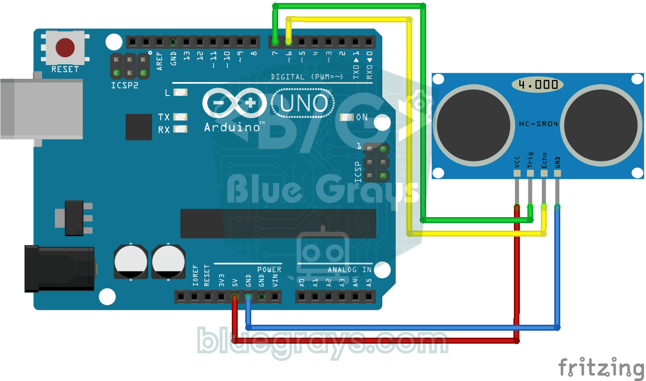
The HC-SR04 sensor works just like a bat finding its way in the dark: it sends out a sound you cannot hear, listens for the echo and measures how far away the object in front of it is. The Arduino wri
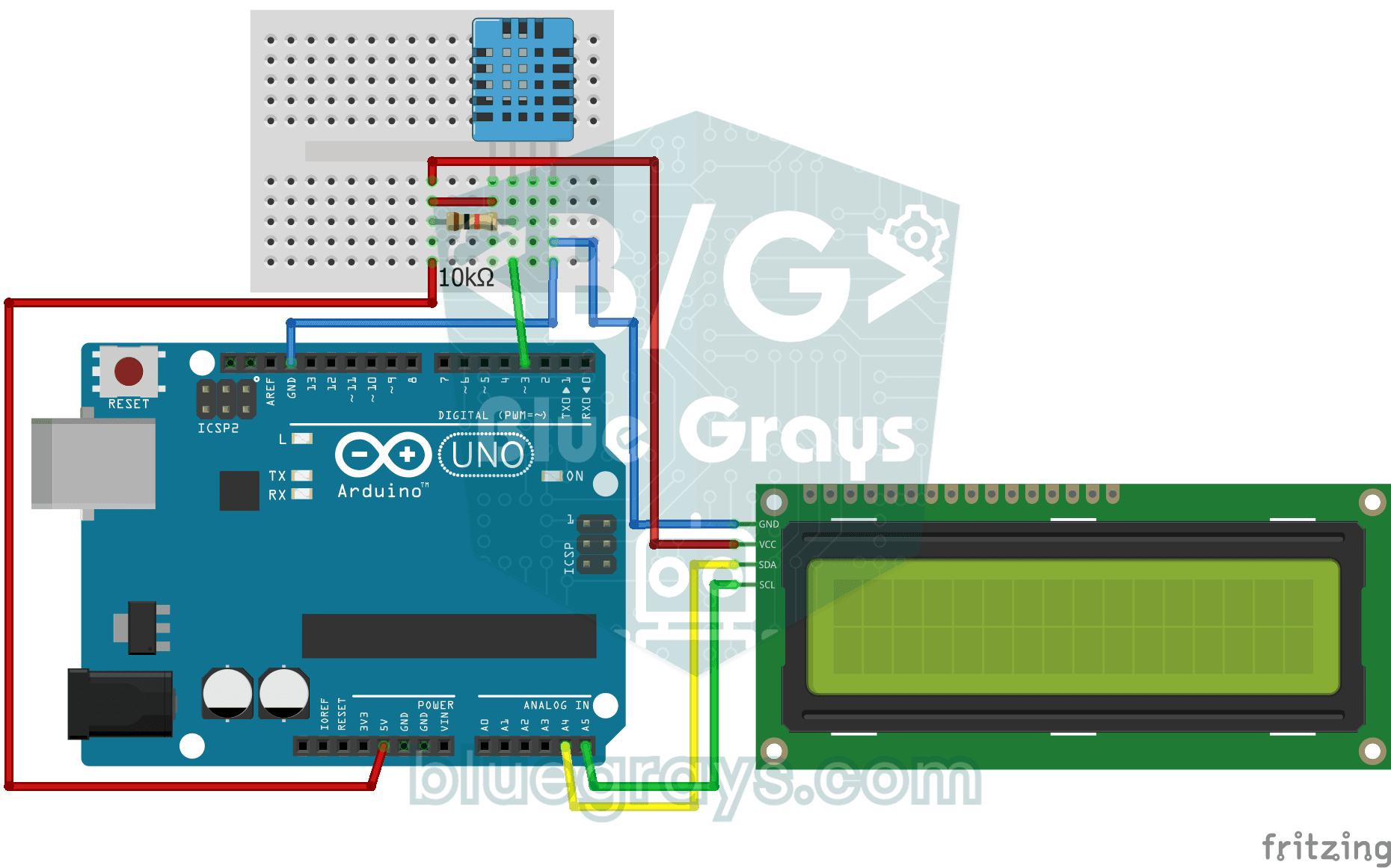
Temperature and Humidity with DHT11
How warm is your room, and is the air humid or dry? The DHT11 sensor measures temperature and humidity, and the Arduino writes the values on a two-line LCD screen, refreshing every couple of seconds.
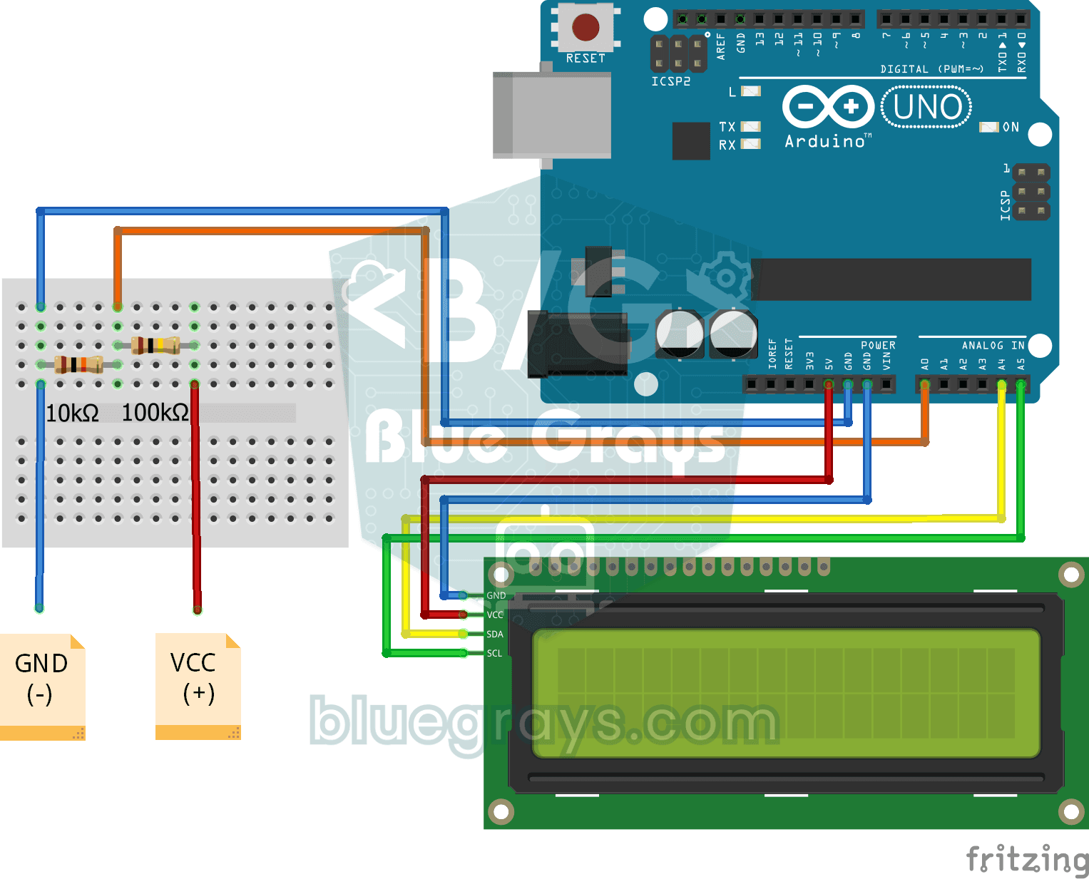
Digital Voltmeter with LCD Display
Find out how much voltage a battery or power adapter gives with a meter you built yourself. A divider made of two resistors brings high voltage down to a level the board can read, and the Arduino calc