
Arduino Water Pump: Wire and Control a Mini Submersible Pump
Arduino water pump guide: drive a 3–6 V mini submersible pump with a MOSFET or relay, flyback diode, separate supply, flow rate, auto watering and ESP32 code.
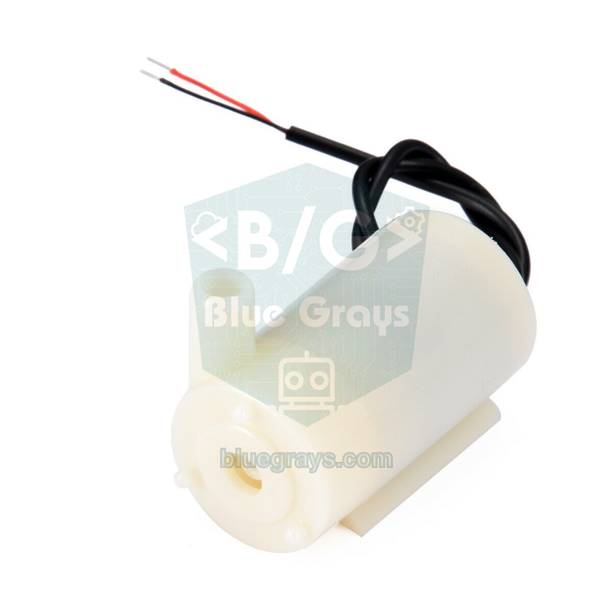
Almost every Arduino water pump project uses the same part: a finger-sized mini submersible pump that runs on 3–6 V and sits completely underwater. It's the heart of circuits that water plant pots, top up an aquarium, dispense a set amount of liquid like a coffee machine or run a small fountain. It's cheap, quiet and has just two wires; but because there's a brushed DC motor inside, you can't connect it directly to an Arduino pin.
In this guide you'll learn step by step what's inside the pump, why it doesn't go straight onto a pin and how to drive it safely with a MOSFET, transistor or relay. We'll talk about the job of the flyback diode, why the pump needs its own power supply, how flow rate relates to head height and why running the pump dry kills it. Then we'll write code for PWM speed control, a liquid dispenser accurate to the millilitre, automatic watering based on soil moisture, phone control with an ESP32 and timed watering with a Raspberry Pi Pico.
What is a mini submersible pump and how does it work?
A mini submersible pump is a centrifugal pump. Inside the plastic housing there's a small brushed DC motor and a vaned impeller mounted on its shaft. As the motor spins, the impeller flings the water it takes in through the bottom inlet outwards and pushes it out through the hose outlet on the side or top. The motor compartment is sealed watertight, while the impeller chamber is full of water. This design has two important consequences: the pump is not self-priming (it can't push air, so it must sit below the water) and the very water it pumps is what cools the impeller and lubricates its bearing.
| Feature | Typical value (3–6 V mini submersible pump) |
|---|---|
| Operating voltage | 2.5–6 V DC (most efficient at 3–5 V) |
| Operating current | 130–220 mA (up to 300 mA at 6 V) |
| Start-up current | 2–3 times the running current for a few milliseconds |
| Power | 0.4–1.5 W |
| Flow rate (open outlet) | 80–120 L/h, roughly 1.3–2 L/min |
| Maximum head | 40–110 cm (the flow drops to zero at this height) |
| Hose | Silicone hose, 5 mm inner and 7–8 mm outer diameter |
| Continuous service life | About 500 hours (brushed motor) |
The values in the table vary from model to model; always check your own pump's label or the seller's data. The two rows that really matter are current and start-up current. A 200 mA pump can briefly draw 400–600 mA at the moment it starts, because the motor hasn't picked up speed yet. If you don't design your circuit for this surge, you'll see your Arduino reset every time the pump switches on.
Why can't the pump go directly onto an Arduino pin?
The most common beginner mistake is plugging the pump's red wire into a digital pin, the black one into GND, and trying to run it with digitalWrite(HIGH). There are three separate problems with that. First, current: an Arduino Uno pin survives at most 40 mA and the safe limit is 20 mA, while the pump wants ten times that. Second, voltage spikes: the motor winding is a coil, and the moment the current is cut it can produce a short pulse of hundreds of volts in the opposite direction. Third, electrical noise: the brushes of a brushed motor spark on every turn and spread interference onto the supply line. The result is either a pump that never spins or a permanently damaged pin.
| Board | Safe current per pin | Absolute pin limit | Compared with the pump |
|---|---|---|---|
| Arduino Uno / Nano (5 V) | 20 mA | 40 mA | The pump wants 5–10 times more |
| ESP32 (3.3 V) | ≈ 20 mA | 40 mA | Not enough current, and the voltage is low too |
| Raspberry Pi Pico (3.3 V) | 4 mA (default) | 12 mA (highest setting) | The pump wants over 20 times more |
The solution is for the pin to control a switch rather than the pump. The pin only provides a signal of a few milliamps; the pump's real current flows from a separate power supply through that switch. You have four options for the switch: a logic-level MOSFET, an NPN transistor, a ready-made MOSFET module or a relay module. The table below sums up when each one makes sense.
| Driving method | PWM speed control | With 3.3 V boards | Note |
|---|---|---|---|
| Logic-level MOSFET (IRLZ44N, AO3400A) | Yes | AO3400A excellent, IRLZ44N enough | Best choice; barely warms up |
| NPN transistor (2N2222A, BC337) | Yes | Yes, use a smaller base resistor | Up to 300 mA; drops ≈ 0.2–0.3 V |
| IRF520 MOSFET module | Yes | No, only half on | Works up to about 1 A at 5 V |
| Relay module | No, on/off only | Needs a 3.3 V trigger module | Clicks, contacts wear; for 12 V or mains pumps |
| L298N / L9110S motor driver | Yes | Yes | No reversing needed; the L298N eats up to 2 V |
Arduino water pump wiring: MOSFET, diode and common ground
The sturdiest and most flexible circuit is an N-channel logic-level MOSFET that switches the pump on the low side. The pump's positive wire goes straight to the positive of the external supply; its negative wire connects to the MOSFET's drain. The MOSFET's source goes to GND and its gate goes to the Arduino pin through a resistor. When the pin goes HIGH, the MOSFET conducts, connects the pump's negative to GND and the pump spins. On the IRLZ44N, with the printed side facing you, the pins from left to right are Gate, Drain, Source.
| Connection | Arduino Uno | ESP32 | Raspberry Pi Pico |
|---|---|---|---|
| Control pin → gate resistor → gate | D9 (PWM), 220 Ω | GPIO 25, 100 Ω | GP15, 100 Ω |
| Pull-down between gate and GND | 10 kΩ | 10 kΩ | 10 kΩ |
| MOSFET source | GND | GND | GND |
| MOSFET drain | Pump negative (black) wire | Pump negative (black) wire | Pump negative (black) wire |
| Pump positive (red) wire | Positive of the external 5 V supply | Positive of the external 5 V supply | Positive of the external 5 V supply |
| Negative of the external supply | Arduino GND (common ground) | ESP32 GND (common ground) | Pico GND (common ground) |
| 1N5819 diode, reverse-parallel to the pump | Cathode (striped end) to pump positive | Cathode to pump positive | Cathode to pump positive |
The gate resistor limits the surge current drawn from the pin while the MOSFET's gate capacitance charges; the 10 kΩ pull-down holds the gate at GND while the Arduino boots or uploads code and the pin is still undefined. Without that resistor, the pump may run by itself for a few seconds on every reset; next to a plant pot, that means a glass of water spilled on your desk. The diode and the common ground are important enough to deserve their own sections.
Flyback diode: the voltage spike when the pump switches off
A motor winding behaves like a coil, and a coil doesn't allow the current through it to stop suddenly. The instant the MOSFET turns off, the energy stored in the winding looks for a way out and creates a short voltage spike on the drain, well above the supply voltage. Over time this pulse punches through the MOSFET or transistor and resets any Arduino on the same line. The fix is a diode connected across the pump's two terminals in reverse: cathode (striped end) to positive, anode to negative. In normal operation the diode carries no current at all; when the MOSFET turns off, the coil's current circulates back through the diode into the pump and the energy dies away harmlessly.
If you'll switch the pump rapidly with PWM, the diode conducts in every period, so a fast Schottky diode like the 1N5819 is the best choice. If you only switch it on and off, the 1N4007 you have lying around will do. To cut down the noise from the brushes, you can also solder a 100 nF ceramic capacitor across the pump terminals. We explain diode types and how to find their direction in what is a diode.
Separate power supply and common ground: why does the Arduino reset?
Powering the pump from the Arduino Uno's 5V pin looks like it works on the first try, but it isn't reliable. A USB-powered Uno sits entirely behind a 500 mA fuse (polyfuse), and a computer's USB port usually supplies 500 mA as well. When the pump starts, its 400–600 mA surge pulls the voltage below 4 V for an instant; the microcontroller resets, the Serial Monitor disconnects or the code behaves strangely. If you plug an adapter into the Uno's barrel jack instead, the board's 5 V regulator heats up: with a 9 V input and a 250 mA pump, the regulator turns (9 − 5) × 0.25 = 1 W into heat.
- 5 V adapter (1–2 A): The most practical solution. The pump and, if needed, the Arduino run from the same adapter, but through separate wires.
- 4 × AA batteries (6 V): Ideal for 6 V pumps; fresh cells give 6.4 V, which is safe for the pump.
- 18650 Li-ion (3.7–4.2 V): Good for 3–5 V pumps; charge it with a TP4056 module.
- Breadboard power module: Modules like the MB102 feed 5 V and 3.3 V to the breadboard; enough for a small pump, details in the breadboard power module guide.
- If you have a 12 V system: Step it down to 5 V with an LM2596 buck converter; never feed 12 V straight into a 6 V pump.
Flow rate and head: how high can the pump lift water?
The 100–120 L/h flow rate that sellers quote is for a pump with no hose attached and its outlet at the water surface. In real use, as the water climbs the hose the pump works against gravity and the flow drops. The height at which the pump can no longer lift water at all is called the maximum head; at that point the impeller spins but nothing comes out of the hose. A long, thin or kinked hose has the same effect by adding friction. The table below shows how a typical pump that delivers about 100 L/h at 5 V with an open outlet behaves at different heights.
| Height from water surface to hose end | Approximate flow | Per second |
|---|---|---|
| 0 cm | 100 L/h | ≈ 28 ml |
| 25 cm | 75 L/h | ≈ 21 ml |
| 50 cm | 50 L/h | ≈ 14 ml |
| 75 cm | 25 L/h | ≈ 7 ml |
| 100 cm | Almost zero | Drop by drop |
So don't calculate watering time from the catalogue figure; measure it on your own setup. Hold the hose over a measuring jug at the height you'll really use, run the pump for exactly 10 seconds and read the water in the jug. If you measured 185 ml, for example, your flow rate is 18.5 ml/s; to deliver 250 ml you need to run the pump for 250 / 18.5 ≈ 13.5 seconds. Repeating the measurement three times and averaging it reduces the error from battery voltage and hose differences. If the pump voltage changes (as batteries run down), so does the flow rate; for precise dosing use a stable 5 V supply.
Running dry and the siphon effect: the pump's two hidden enemies
Water is what lubricates the pump's bearing and cools its motor. When the tank runs empty, the pump spins in air, the impeller bearing heats up from friction, plastic parts soften and the motor races faster than normal. A few seconds of dry running won't kill most pumps, but a pump that runs dry for minutes either seizes or starts to sound different and loses flow. In automatic systems there are two ways to prevent this: put a water level sensor or float switch in the tank, and limit in code how long the pump may run in one go. The automatic watering code below does both.
Step by step: your first pump test
- Fully submerge the pump in a container of water and fit 30–50 cm of silicone hose to the outlet; point the end of the hose into a second container.
- Place the IRLZ44N on the breadboard. Connect the gate to D9 through 220 Ω and also to GND through 10 kΩ; connect the source to GND.
- Connect the pump's black wire to the drain and its red wire to the positive of the external 5 V supply. Fit the 1N5819 diode across the pump terminals with the striped end on the positive side.
- Connect the external supply's negative to the Arduino's GND; check the wiring once more, then switch the supply on.
- Upload the code below and open the Serial Monitor at 9600 baud. The pump should run for 3 seconds and stop for 10.
1const byte PUMP_PIN = 9;            // MOSFET gate (220 Ω üzerinden) / MOSFET gate (through 220 Ω)
2
3void setup() {
4  pinMode(PUMP_PIN, OUTPUT);
5  digitalWrite(PUMP_PIN, LOW);      // açılışta pompa kapalı / pump off at start-up
6  Serial.begin(9600);
7}
8
9void loop() {
10  Serial.println(F("Pompa calisiyor / pump on"));
11  digitalWrite(PUMP_PIN, HIGH);     // MOSFET iletimde, pompa döner / MOSFET on, pump runs
12  delay(3000);                      // 3 saniye su bas / pump for 3 seconds
13  Serial.println(F("Pompa durdu / pump off"));
14  digitalWrite(PUMP_PIN, LOW);
15  delay(10000);                     // 10 saniye bekle / wait 10 seconds
16}
If the pump doesn't run, check the common ground first, then the MOSFET's pin order; if it won't stop, the drain and source may be swapped. To measure the flow rate, just change delay(3000) to delay(10000) in the same code and hold the hose over a measuring jug. Because this code uses delay(), the Arduino can't do anything else while the pump runs; in the next examples we'll keep time with millis(). If you're curious about the difference, have a look at millis versus delay.
Adjusting pump speed with PWM
The biggest advantage of a MOSFET is that you can set the pump speed with PWM. A slow flow looks more natural in a fountain, stirs up less dirt in an aquarium filter and allows finer dosing. There are two practical problems. First, small pumps can't start at a low duty cycle (usually below 30–40%) and just hum; so the code kicks the pump off with a short full-power pulse and then drops to the requested speed. Second, the 490 Hz PWM on the Uno's D9 pin makes the pump whine audibly; the code raises that frequency to 3.9 kHz.
1const byte PUMP_PIN = 9;            // MOSFET gate, Timer1 PWM pini / Timer1 PWM pin
2const byte POT_PIN = A0;            // hız potansiyometresi / speed potentiometer
3const byte MIN_DUTY = 90;           // bunun altında pompa dönmez (≈ %35) / pump stalls below this (≈ 35 %)
4
5byte duty = 0;
6
7void setup() {
8  // D9-D10 PWM frekansı 490 Hz yerine 3,9 kHz (daha az vızıltı) / D9-D10 PWM at 3.9 kHz instead of 490 Hz (less whine)
9  TCCR1B = (TCCR1B & 0b11111000) | 0x02;
10  pinMode(PUMP_PIN, OUTPUT);
11  Serial.begin(9600);
12}
13
14void loop() {
15  int raw = analogRead(POT_PIN);                    // 0-1023
16  byte target = map(raw, 0, 1023, 0, 255);
17  if (target < MIN_DUTY) target = 0;                // çok yavaşsa tamamen durdur / stop completely if too slow
18
19  if (duty == 0 && target > 0) {                    // pompa duruyordu, şimdi kalkacak / pump was stopped, now starting
20    analogWrite(PUMP_PIN, 255);                     // kısa tam güç darbesi / short full-power kick
21    delay(150);
22  }
23  duty = target;
24  analogWrite(PUMP_PIN, duty);
25
26  Serial.print(F("PWM: "));
27  Serial.print(duty);
28  Serial.print(F("  (%"));
29  Serial.print(duty * 100 / 255);
30  Serial.println(F(")"));
31  delay(100);
32}
Connect the potentiometer's middle pin to A0 and its outer pins to 5V and GND. The TCCR1B line only affects Timer1, meaning pins D9 and D10; millis() and delay() use Timer0, so they keep working. However, the Servo library also uses Timer1, so remove this line if your project has a servo. Find MIN_DUTY with your own pump: turn the potentiometer slowly, read the lowest value at which the pump can start by itself in the Serial Monitor and add a little margin. Lowering the pump voltage also lowers the head; at half speed the pump can only lift water to about a quarter of its full-speed height, because a centrifugal pump's pressure is proportional to the square of its speed.
Liquid dispenser: exactly 50 ml at the press of a button
Once you've measured the flow rate, turning the pump into a dosing machine is easy: divide the required amount by the flow rate and you get how long the pump has to run. The code below dispenses 50 ml every time you press a button wired between D2 and GND; pressing the button again while the pump is running cancels the dose. Because time is measured with millis(), the loop never waits and can read the button all the time. This is the basis of projects like soap dispensers, plant fertiliser dosers or cocktail machines.
1const byte PUMP_PIN = 9;                 // MOSFET gate / MOSFET gate
2const byte BUTTON_PIN = 2;               // buton: D2 ile GND arası / button between D2 and GND
3const float ML_PER_SECOND = 18.5;        // kendi ölçtüğün debi / the flow rate you measured
4const float DOSE_ML = 50.0;              // bir basışta verilecek miktar / amount per press
5
6unsigned long doseTime = 0;              // ms cinsinden doz süresi / dose time in ms
7unsigned long startTime = 0;
8unsigned long lastPress = 0;
9bool pumping = false;
10bool lastButton = HIGH;
11
12void setPump(bool on) {
13  pumping = on;
14  digitalWrite(PUMP_PIN, on ? HIGH : LOW);
15  if (on) startTime = millis();
16}
17
18void setup() {
19  pinMode(PUMP_PIN, OUTPUT);
20  digitalWrite(PUMP_PIN, LOW);
21  pinMode(BUTTON_PIN, INPUT_PULLUP);     // basılıyken LOW / LOW while pressed
22  Serial.begin(9600);
23  doseTime = (unsigned long)(DOSE_ML / ML_PER_SECOND * 1000.0);
24  Serial.print(F("Doz suresi / dose time (ms): "));
25  Serial.println(doseTime);              // 50 / 18,5 = 2703 ms
26}
27
28void loop() {
29  bool button = digitalRead(BUTTON_PIN);
30  if (button == LOW && lastButton == HIGH && millis() - lastPress > 200) {   // yeni basış, 200 ms debounce / new press, 200 ms debounce
31    lastPress = millis();
32    setPump(!pumping);                   // ilk basış başlatır, ikincisi iptal eder / first press starts, second cancels
33    Serial.println(pumping ? F("Doz basladi / dose started") : F("Iptal / cancelled"));
34  }
35  lastButton = button;
36
37  if (pumping && millis() - startTime >= doseTime) {   // süre doldu / time is up
38    setPump(false);
39    Serial.println(F("Doz tamam / dose done"));
40  }
41}
If the first dose comes out smaller than the rest, the cause is most likely an empty hose: the pump fills the hose first and only then delivers liquid. Keeping the hose end slightly above the water in the tank keeps the hose full, so every dose is the same. With thick liquids like oil, syrup or soap the flow rate is much lower than with water, so always calibrate with that liquid. For projects that touch food, use food-grade silicone hose and rinse the pump with clean water after every use.
Automatic watering based on soil moisture
The most popular Arduino water pump project is a plant pot that waters itself when the soil dries out. The trap beginners fall into is running the pump until the soil moisture reaches the target: it takes minutes for water to reach the sensor, and by then the pot has overflowed. The right method is watering in short pulses: the pump runs for 4 seconds, then waits 1 minute for the water to spread through the soil and measures the moisture again. The code also never runs the pump if the tank is empty, and if the moisture still hasn't risen after 6 pulses (the sensor may have come out of the soil or the hose may have come off), it locks the system and lights the LED. We cover sensor calibration in detail in the soil moisture sensor guide.
1const byte PUMP_PIN = 9;                 // MOSFET gate / MOSFET gate
2const byte SOIL_PIN = A0;                // kapasitif toprak nem sensörü AOUT / capacitive soil sensor AOUT
3const byte FLOAT_PIN = 3;                // şamandıra: D3 ile GND arası / float switch between D3 and GND
4const byte LED_PIN = 13;                 // uyarı LED'i / warning LED
5
6const int DRY_VALUE = 600;               // sensör kuru havadayken / sensor in dry air
7const int WET_VALUE = 280;               // sensör bardak sudayken / sensor in a glass of water
8const int START_PERCENT = 35;            // bunun altında sulamaya başla / start watering below this
9const int STOP_PERCENT = 55;             // buna ulaşınca dur / stop once this is reached
10const unsigned long PULSE_MS = 4000;     // bir darbede pompa süresi / pump time per pulse
11const unsigned long SOAK_MS = 60000;     // suyun toprağa yayılma süresi / time for the water to soak in
12const byte MAX_PULSES = 6;               // bir sulamada en fazla darbe / max pulses per watering
13
14byte pulses = 0;
15bool locked = false;
16unsigned long lastCheck = 0;
17
18bool waterAvailable() {
19  return digitalRead(FLOAT_PIN) == LOW;  // şamandıra yukarıda: kontak kapalı / float up: contact closed
20}
21
22int readMoisture() {
23  long sum = 0;
24  for (byte i = 0; i < 10; i++) {        // 10 ölçümün ortalaması / average of 10 readings
25    sum += analogRead(SOIL_PIN);
26    delay(5);
27  }
28  int percent = map(sum / 10, DRY_VALUE, WET_VALUE, 0, 100);
29  return constrain(percent, 0, 100);
30}
31
32void runPump(unsigned long ms) {
33  unsigned long t0 = millis();
34  digitalWrite(PUMP_PIN, HIGH);
35  while (millis() - t0 < ms) {
36    if (!waterAvailable()) break;        // su biterse hemen dur / stop at once if the water runs out
37  }
38  digitalWrite(PUMP_PIN, LOW);
39}
40
41void setup() {
42  pinMode(PUMP_PIN, OUTPUT);
43  digitalWrite(PUMP_PIN, LOW);
44  pinMode(FLOAT_PIN, INPUT_PULLUP);
45  pinMode(LED_PIN, OUTPUT);
46  Serial.begin(9600);
47  lastCheck = millis() - SOAK_MS;        // ilk ölçüm hemen yapılsın / take the first reading right away
48}
49
50void loop() {
51  if (!waterAvailable()) {               // depo boş: yavaş yanıp sön / tank empty: slow blink
52    digitalWrite(LED_PIN, (millis() / 500) % 2);
53    return;
54  }
55  if (locked) {                          // arıza: LED sürekli yanar / fault: LED stays on
56    digitalWrite(LED_PIN, HIGH);
57    return;
58  }
59  digitalWrite(LED_PIN, LOW);
60  if (millis() - lastCheck < SOAK_MS) return;
61  lastCheck = millis();
62
63  int moisture = readMoisture();
64  Serial.print(F("Nem / moisture: %"));
65  Serial.println(moisture);
66
67  if (pulses == 0 && moisture >= START_PERCENT) return;   // sulama gerekmiyor / no watering needed
68  if (moisture >= STOP_PERCENT) {                        // hedefe ulaşıldı / target reached
69    pulses = 0;
70    return;
71  }
72  if (pulses >= MAX_PULSES) {                            // nem yükselmiyor: sensör ya da hortum sorunu / moisture not rising: sensor or hose problem
73    locked = true;
74    Serial.println(F("Kilitlendi, kontrol et / locked, check the setup"));
75    return;
76  }
77  runPump(PULSE_MS);
78  pulses++;
79}
Using two separate thresholds in the code is deliberate: watering starts when moisture drops below 35% but continues until it reaches 55%. Thanks to this hysteresis, the pump doesn't keep switching on and off because of a reading that wobbles right at the threshold. Measure DRY_VALUE and WET_VALUE with your own sensor; on capacitive sensors these values depend on the supply voltage and cable length. If the float switch wire breaks, the pin reads HIGH and the code treats it as an empty tank; in other words, if something fails, the system stays on the safe side and stops the pump. If you want watering only at certain times of day, add an RTC clock module and put a time check into the condition.
When does a relay make sense for pump control?
If all you have is a relay module, you can run the mini pump with it too: the pump's positive lead goes from the external supply to the relay's COM terminal and from the NO terminal to the pump; the negative lead goes to the supply's negative. The relay fully isolates the pump from the board's circuit, and the same module can switch large 12 V pumps or mains-powered aquarium pumps. On the other hand, a relay can't do PWM speed control, clicks on every switch, its contacts wear over time and its coil alone draws around 70 mA. If you switch the pump a few times a day, a relay will do; if you need dosing or speed control, a MOSFET is always better. Even with a relay, a diode across the pump reduces contact arcing.
Controlling the water pump from your phone with an ESP32
Thanks to the ESP32's Wi-Fi, you can run the pump from your phone's browser. The code below starts a small web server on the ESP32; when you open the IP address shown in the Serial Monitor on a phone on the same network, you'll see buttons for 5 and 15 seconds of watering and a stop button. No extra library is needed, as WebServer comes with the ESP32 core. For safety, the pump never runs longer than 30 seconds; even if the connection drops, it stops by itself when the time is up. Because the ESP32 runs at 3.3 V, choose a MOSFET that fully turns on at 3.3 V: the AO3400A is best, and the IRLZ44N is still comfortably enough for a mini pump's 300 mA.
1#include <WiFi.h>
2#include <WebServer.h>
3
4const char* WIFI_SSID = "AgAdi";             // Wi-Fi adın (2,4 GHz) / your Wi-Fi name (2.4 GHz)
5const char* WIFI_PASS = "Sifre123";          // Wi-Fi şifren / your Wi-Fi password
6const int PUMP_PIN = 25;                     // MOSFET gate, 100 Ω üzerinden / through 100 Ω
7const unsigned long MAX_RUN_MS = 30000;      // güvenlik: en uzun çalışma / safety: longest run
8
9WebServer server(80);
10bool pumpOn = false;
11unsigned long pumpStart = 0;
12unsigned long pumpDuration = 0;
13
14void startPump(unsigned long ms) {
15  if (ms > MAX_RUN_MS) ms = MAX_RUN_MS;
16  pumpDuration = ms;
17  pumpStart = millis();
18  pumpOn = true;
19  digitalWrite(PUMP_PIN, HIGH);
20}
21
22void stopPump() {
23  pumpOn = false;
24  digitalWrite(PUMP_PIN, LOW);
25}
26
27void handleRoot() {
28  String html = F("<!DOCTYPE html><html><head><meta charset='utf-8'>"
29                  "<meta name='viewport' content='width=device-width,initial-scale=1'>"
30                  "<title>Pompa</title></head><body style='font-family:sans-serif;text-align:center'>"
31                  "<h2>BlueGrays Pompa</h2><p>");
32  html += pumpOn ? "Pompa çalışıyor / pump is on" : "Pompa kapalı / pump is off";
33  html += F("</p><p><a href='/run?s=5'><button>5 sn</button></a> "
34            "<a href='/run?s=15'><button>15 sn</button></a> "
35            "<a href='/stop'><button>Durdur / Stop</button></a></p></body></html>");
36  server.send(200, "text/html", html);
37}
38
39void goHome() {                              // ana sayfaya geri dön / go back to the main page
40  server.sendHeader("Location", "/");
41  server.send(303);
42}
43
44void handleRun() {
45  long seconds = server.arg("s").toInt();     // /run?s=5 → 5 saniye / 5 seconds
46  if (seconds > 0) startPump(seconds * 1000UL);
47  goHome();
48}
49
50void handleStop() {
51  stopPump();
52  goHome();
53}
54
55void setup() {
56  pinMode(PUMP_PIN, OUTPUT);
57  digitalWrite(PUMP_PIN, LOW);
58  Serial.begin(115200);
59  WiFi.mode(WIFI_STA);
60  WiFi.begin(WIFI_SSID, WIFI_PASS);
61  while (WiFi.status() != WL_CONNECTED) {
62    delay(500);
63    Serial.print(".");
64  }
65  Serial.println();
66  Serial.print(F("Tarayicida ac / open in the browser: http://"));
67  Serial.println(WiFi.localIP());
68
69  server.on("/", handleRoot);
70  server.on("/run", handleRun);
71  server.on("/stop", handleStop);
72  server.begin();
73}
74
75void loop() {
76  server.handleClient();
77  if (pumpOn && millis() - pumpStart >= pumpDuration) {   // süre doldu / time is up
78    stopPump();
79  }
80}
This page only opens from your home Wi-Fi network. If you also want to control the pump from outside or get a notification when the tank runs dry, you can add the methods from the ESP32 Telegram bot or Blynk guides to this code. To turn the page into a dashboard that updates instantly over WebSocket, see the ESP32 Async Web Server guide. Since the ESP32's pins output 3.3 V, an IRF520 module won't work here; if you want a module, pick one with a logic-level MOSFET.
Timed watering with a Raspberry Pi Pico (MicroPython)
On the Pico, you can drive the pump through a MOSFET on GP15 and give it a soft start with PWM. A soft start spreads the pump's start-up current over a few hundred milliseconds and prevents a sudden dip in the supply voltage; if the Pico and the pump share the same supply, this avoids random resets. The code below waters for 8 seconds every 12 hours and adds an extra 3 seconds when you press the button on GP14. Since the Pico's pins only give 3.3 V, prefer a MOSFET that's guaranteed at 3.3 V like the AO3400A here too. If you're new to MicroPython, take a look at what is a Raspberry Pi Pico first.
1from machine import Pin, PWM
2import time
3
4pump = PWM(Pin(15))                       # MOSFET gate, 100 Ω üzerinden / through 100 Ω
5pump.freq(1000)                           # 1 kHz PWM
6pump.duty_u16(0)                          # açılışta kapalı / off at start-up
7button = Pin(14, Pin.IN, Pin.PULL_UP)     # buton: GP14 ile GND arası / button between GP14 and GND
8
9INTERVAL_MS = 12 * 60 * 60 * 1000         # 12 saatte bir / every 12 hours
10WATER_MS = 8000                           # her seferde 8 saniye / 8 seconds each time
11SPEED = 0.8                               # %80 hız / 80 % speed
12
13def water(ms):
14    top = int(65535 * SPEED)
15    for d in range(0, top, 2000):         # yumuşak kalkış (≈ 0,3 s) / soft start (≈ 0.3 s)
16        pump.duty_u16(d)
17        time.sleep_ms(10)
18    pump.duty_u16(top)
19    time.sleep_ms(ms)
20    pump.duty_u16(0)                      # pompayı durdur / stop the pump
21    print("Sulandi / watered:", ms, "ms")
22
23last = time.ticks_ms()
24while True:
25    if time.ticks_diff(time.ticks_ms(), last) >= INTERVAL_MS:
26        last = time.ticks_ms()
27        water(WATER_MS)
28    if button.value() == 0:               # elle sulama / manual watering
29        water(3000)
30        while button.value() == 0:        # bırakılmasını bekle / wait for release
31            time.sleep_ms(10)
32    time.sleep_ms(50)
The code measures time with time.ticks_diff(), which returns the right difference even when the counter wraps around. Because the Pico's own clock resets when it's powered off and can drift a few seconds a day, if you want a schedule tied to real time, like "water every morning at 07:00", add an RTC module or use a Pico W and fetch the time from the internet (NTP). After a power cut, the 12-hour counter starts again from zero; that's fine for most plants, but keep it in mind for projects that run while you're away on a long holiday.
Project ideas with a mini water pump
- Holiday watering system: Water your plants for two weeks with a bucket of water, a few pots and thin hoses branching out to each pot; the full setup is in the smart greenhouse project.
- Automatic pet water bowl: When the water level in the bowl drops, the pump tops it up from a tank; a contactless liquid level sensor works well for the level.
- Touchless soap or sanitiser dispenser: When an HC-SR04 or infrared sensor sees a hand, the pump runs for half a second.
- Cocktail and drink machine: 3–4 pumps, each in its own bottle and each with its flow rate measured separately, mix drinks by recipe.
- Desktop waterfall and decorative pond: A fountain whose flow slows down at night with PWM and switches off when an LDR sees the room go dark.
- Aquarium top-off: A system that replaces evaporated water from a separate tank when a float switch shows the level has dropped.
- Smart home integration: Link the pump to your other devices through MQTT and Home Assistant with an ESP32.
Common mistakes and how to fix them
| Symptom | Likely cause | Fix |
|---|---|---|
| The pump hums but doesn't push water | Air trapped inside, or the pump is above the water level | Submerge the pump fully and shake it gently to release the air; lay the hose without kinks |
| The Arduino resets when the pump starts | The pump runs from the Arduino's 5V pin, or there's no diode | Power the pump from a separate 5 V supply, add a reverse-parallel 1N5819 and 100 nF |
| The pump doesn't run at all | No common ground, or the MOSFET pins are in the wrong order | Connect the external supply's negative to Arduino GND and check the G-D-S order |
| The pump runs briefly while the Arduino boots | Floating gate, no pull-down resistor | Put 10 kΩ between gate and GND |
| Water keeps flowing after the pump stops | Siphon effect: the hose end is below the tank level | Raise the hose or make a small air hole at the top of the hose |
| The flow rate drops over time | Clogged inlet screen, weak batteries or wear from running dry | Clean the inlet, measure the supply, add a water level sensor |
| The pump won't spin at low PWM | Duty cycle below the motor's starting threshold | Give a short full-power kick at start and raise MIN_DUTY |
Driven correctly, a mini submersible pump is a cheap, quiet part that will work for years without trouble: with a logic-level MOSFET, a reverse diode, a separate 5 V supply and a common ground, your Arduino stays completely safe. The rest is up to your imagination; with the flow rate you measured you can dose to the millilitre, water by soil moisture or manage the pump from your phone with an ESP32. In the BlueGrays app you'll find the Smart Irrigation Station project, along with ESP32 web server and RTC clock projects, with step-by-step circuit diagrams and code.
Frequently asked questions
How do you connect a water pump to an Arduino?
A mini water pump doesn't connect directly to an Arduino pin, because a pin delivers 20–40 mA while the pump needs 150–300 mA. Connect the pump's positive to an external 5 V supply and its negative to the drain of a logic-level MOSFET like the IRLZ44N; wire the gate to a pin through 220 Ω and the source to GND. Add a 1N5819 diode in reverse parallel across the pump and join the grounds of both supplies.
How much current does a mini water pump draw?
3–6 V mini submersible pumps usually draw 130–220 mA while running, and up to 300 mA at 6 V. At start-up they can briefly reach 2–3 times that value for a few milliseconds. That's why your supply should be rated for at least 1 A and the pump shouldn't run from the Arduino's 5V pin.
Should I drive a water pump with a relay or a MOSFET?
For mini 3–6 V pumps a logic-level MOSFET is better: it's silent, doesn't wear out and allows PWM speed control. A relay can only switch on and off, clicks and its coil draws about 70 mA on top. A relay makes sense for large 12 V pumps or mains-powered pumps, and when the pump runs only a few times a day.
What happens if a mini water pump runs dry?
These pumps are cooled by water and their bearing is lubricated by it. A few seconds of dry running usually does no harm, but a pump that runs dry for minutes overheats its bearing, wears its plastic parts and can seize. In automatic systems, put a water level sensor or float switch in the tank and limit the longest run time in code.
How high can a mini water pump lift water?
The maximum head of 3–6 V mini submersible pumps is usually between 40 and 110 cm. As you approach that height the flow rate falls quickly, and at the limit almost no water comes out of the hose. If you need to send water higher, use a stronger 12 V pump or a diaphragm pump.
Can you control a water pump's speed with an Arduino?
Yes. If you drive the pump through a logic-level MOSFET, you can set its speed with analogWrite() on a PWM pin. Small pumps can't start below a duty cycle of about 30–40%, so give a short full-power kick first and then lower the speed. You can't control the speed with a relay.
Projects to build after reading this
See all projects
Smart Irrigation Station
A gardener that waters your plants on its own, so they don't dry out while you're on vacation. A soil moisture sensor measures how wet the soil is; when it gets dry, the Arduino runs the water pump fo

ESP32 Asynchronous Web Server (with IP Display on LCD)
In this project, we’re turning the ESP32 into an asynchronous web server that you can control from your phone or computer on the same Wi-Fi network. Thanks to the ESPAsyncWebServer library, the server can process multiple requests simultaneously (unlike the classic WebServer.h, which blocks on a single request). You’ll be able to open the ESP32’s IP address in a browser and click the ON/OFF buttons (the /on and /off routes) to turn the LED connected to GPIO 5 on and off.

ESP32 Wi-Fi STA Connection (with LCD Screen)
In this project, we connect the ESP32 to the home Wi-Fi network in Station (STA) mode in a secure, fault-tolerant manner. We store the SSID and password in a separate secrets.h file to prevent leaking to Git, set up an auto-reconnect mechanism, and display the RSSI signal level and IP address on an I2C LCD screen. The internal LED works as a status indicator. It is a production-grade connection manager.

Digital Clock with ESP32 and DS1307 RTC (I2C + LCD)
In this project, we display the time and date on a 16x2 I2C LCD screen using the DS1307 real-time clock (RTC) module. The DS1307 is a battery-backed RTC that maintains the time even if the ESP32 is powered off. Both modules share the same I2C bus (SDA/SCL), allowing us to learn how to control multiple devices using just two signal wires. Through this project, you will gain practical knowledge of the I2C communication protocol, RTC module operation, and dynamic data display on an LCD screen.
DS1302 RTC Clock Module Setup
You get a small clock module running that never forgets the time, even when the Arduino is switched off. The module has its own tiny battery, and once the clock is set, the date and time are printed o
Control an LED from Your Phone via Bluetooth
A small rehearsal for switching the lights in your room on and off from your phone. The Bluetooth module passes the letters sent from your phone to the Arduino; one letter turns on the red LED, anothe

ESP32 Smart Lighting (PIR + LDR + Relay + OLED)
Turn your hallway, bathroom, or pantry into smart lighting with ESP32! Using a PIR motion sensor, LDR light sensor, and a relay module, we build the classic "light turns on when motion is detected in the dark" scenario — if the environment is already bright, motion does NOT trigger the light, saving energy during the day. The light stays on for 30 seconds; if motion continues, the timer resets and the light stays on longer. The SSD1306 OLED shows large-font status (ON / DAYTIME / WAITING), a cou