
Arduino Uno Pinout: Digital, PWM, Analog and Power Pins Explained
Arduino Uno pinout in one table: digital pins 0–13, PWM ~3, 5, 6, 9, 10, 11, analog A0–A5, Vin, 5V, 3.3V, I2C, SPI, interrupt pins and the 20 mA pin limit.
The Arduino Uno pinout covers the 32 connection points lined up on the black female headers along the two long edges of the board: 14 digital input/output pins (0–13), 6 of which can output PWM (~3, 5, 6, 9, 10, 11), 6 analog inputs (A0–A5) and the power pins that feed the board or supply power to other parts (Vin, 5V, 3.3V, GND, IOREF, AREF, RESET). Every pin has a main job, but many carry a second one as well: A4 and A5 are also the I2C bus, 10–13 form the SPI bus, 2 and 3 are interrupt pins, and 0 and 1 are the serial line that talks to your computer.
Choosing the right pin is the difference between a project that works on the first try and hours of debugging. With the tables in this article you'll easily understand why PWM on pins 9 and 10 stops once you attach a servo, why your sketch won't upload while a Bluetooth module is connected, or why a handful of LEDs can overload the board. At the end you'll also find a test sketch that exercises every pin type at once, a sample pin plan and the pin differences between the Uno R3 and R4.
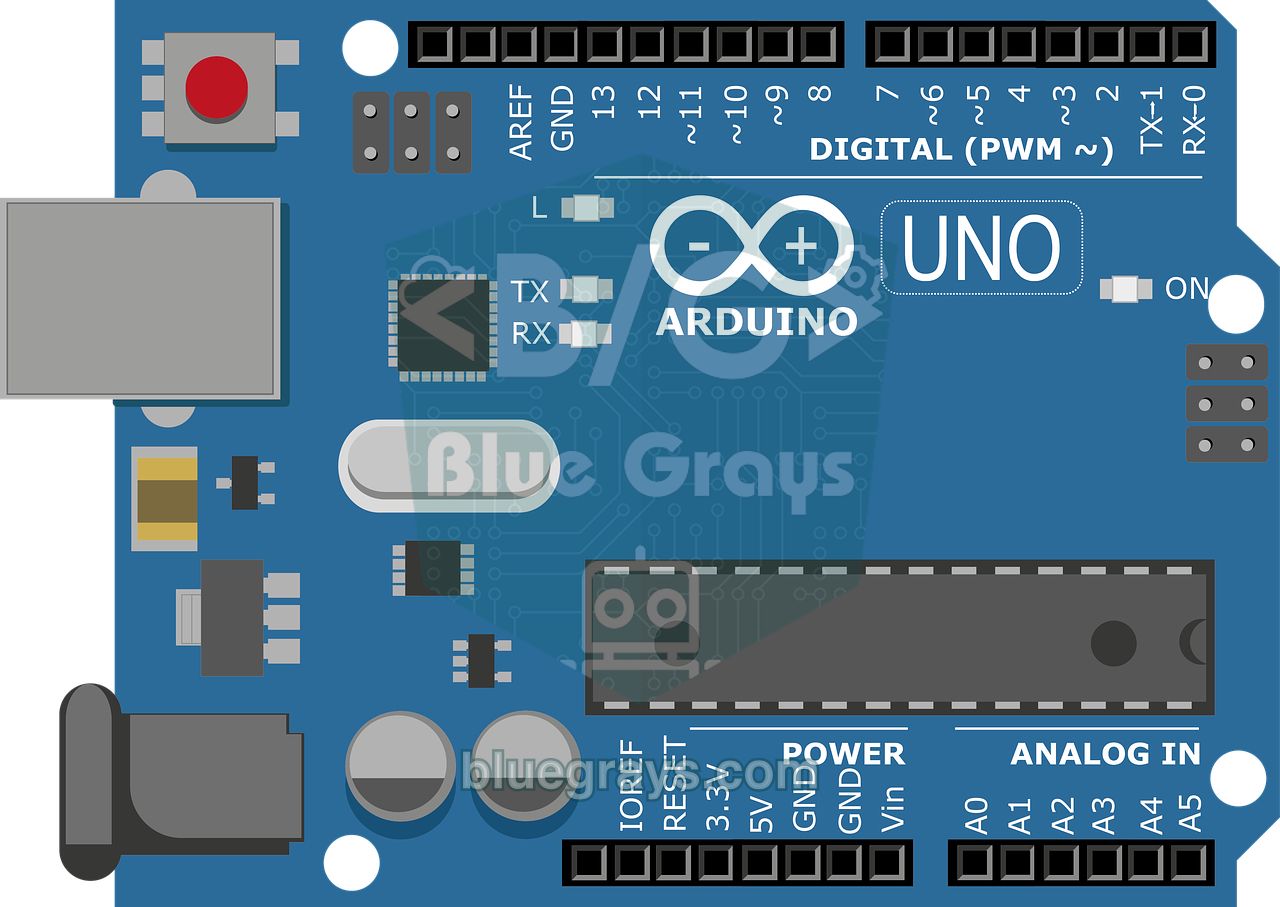
Arduino Uno pin diagram: where is each pin?
Place the board in front of you with the USB socket and the power jack on the left. The two headers along the top edge hold the digital pins; the numbers increase from right to left, so the rightmost pin is 0 (RX) and the leftmost digital pin is 13. Along the bottom edge, the left header carries the power pins and the right header the analog inputs. The ~ (tilde) next to a number means that pin can output PWM. The 2×3 group of male pins on the right edge of the board is the ICSP header.
| Header | Pins (left to right) | Purpose |
|---|---|---|
| Top left (10 pins) | SCL, SDA, AREF, GND, 13, 12, ~11, ~10, ~9, 8 | I2C copy, analog reference, SPI and digital pins |
| Top right (8 pins) | 7, ~6, ~5, 4, ~3, 2, TX→1, RX←0 | Digital pins, interrupt pins and the serial line |
| Bottom left (8 pins) | Unused (NC), IOREF, RESET, 3.3V, 5V, GND, GND, Vin | Power pins |
| Bottom right (6 pins) | A0, A1, A2, A3, A4, A5 | Analog inputs (A4/A5 are also I2C) |
| Right edge (2×3) | 1 MISO, 2 5V, 3 SCK, 4 MOSI, 5 RESET, 6 GND | ICSP programming header |
| Feature | Arduino Uno R3 |
|---|---|
| Microcontroller | ATmega328P, 16 MHz |
| Operating (logic) voltage | 5 V |
| Input voltage (jack / Vin) | 7–12 V recommended, 6–20 V limit |
| Digital I/O | 14 pins (D0–D13) |
| PWM output | 6 pins: 3, 5, 6, 9, 10, 11 |
| Analog input | 6 pins (A0–A5), 10-bit (0–1023) |
| Current per pin | 20 mA recommended, 40 mA absolute maximum |
| Total current (VCC/GND) | 200 mA |
| 3.3V pin current | 50 mA max |
| Memory | 32 KB flash (0.5 KB bootloader), 2 KB SRAM, 1 KB EEPROM |
The big pin table: D0–D13 and A0–A5
| Pin | Port | Main function | Extra function | Note |
|---|---|---|---|---|
| D0 (RX) | PD0 | Digital I/O | UART RX (Serial) | Wired to the USB-serial chip, leave free |
| D1 (TX) | PD1 | Digital I/O | UART TX (Serial) | Wired to the USB-serial chip, leave free |
| D2 | PD2 | Digital I/O | External interrupt INT0 | Buttons, encoders, RPM counting |
| D3 ~ | PD3 | Digital I/O, PWM 490 Hz | External interrupt INT1, Timer2 | PWM is disturbed while tone() plays |
| D4 | PD4 | Digital I/O | - | No extra function, free to use |
| D5 ~ | PD5 | Digital I/O, PWM 980 Hz | Timer0 | Same timer as millis() |
| D6 ~ | PD6 | Digital I/O, PWM 980 Hz | Timer0 | Same timer as millis() |
| D7 | PD7 | Digital I/O | - | No extra function, free to use |
| D8 | PB0 | Digital I/O | - | No extra function, free to use |
| D9 ~ | PB1 | Digital I/O, PWM 490 Hz | Timer1 | The Servo library disables its PWM |
| D10 ~ | PB2 | Digital I/O, PWM 490 Hz | SPI SS, Timer1 | Must stay an output when using SPI |
| D11 ~ | PB3 | Digital I/O, PWM 490 Hz | SPI MOSI, Timer2 | Also on the ICSP header |
| D12 | PB4 | Digital I/O | SPI MISO | Also on the ICSP header |
| D13 | PB5 | Digital I/O | SPI SCK | The onboard L LED is on this pin |
| A0 | PC0 | Analog input | Digital 14 | - |
| A1 | PC1 | Analog input | Digital 15 | - |
| A2 | PC2 | Analog input | Digital 16 | - |
| A3 | PC3 | Analog input | Digital 17 | - |
| A4 | PC4 | Analog input | I2C SDA, digital 18 | No analog readings while I2C is in use |
| A5 | PC5 | Analog input | I2C SCL, digital 19 | No analog readings while I2C is in use |
How do the digital pins (0–13) work?
Each digital pin is set as an input or an output with pinMode(). As an output, digitalWrite(pin, HIGH) pulls the pin to about 5 V and LOW pulls it to 0 V. As an input, digitalRead() compares the voltage with a threshold: with the ATmega328P running at 5 V, anything above 3.0 V is a guaranteed HIGH, anything below 1.5 V a guaranteed LOW, and the range in between is undefined. That's why the output of a 3.3 V sensor usually reads as HIGH on the Uno; but the Uno's 5 V output must not go straight into the input of a 3.3 V module, you need a logic level converter in between.
An input pin that isn't connected to anything is floating and reads random HIGH and LOW values, even when you just move your hand closer. The fix is to pull the pin to a fixed level with a resistor: pinMode(pin, INPUT_PULLUP) switches on the 20–50 kΩ resistor inside the chip, and the button goes between the pin and GND. The details are in How to Connect a Button to Arduino. Pin 13 is connected to the onboard L LED; on a genuine R3 this LED is driven through an op-amp buffer, so using the pin as an input causes no trouble, but on some clone boards the LED and its resistor sit directly on the pin and can upset button readings with the internal pull-up.
PWM pins (~3, 5, 6, 9, 10, 11) and timers
The Uno can't produce a true analog output; instead these six pins provide PWM, a square wave that switches on and off very quickly. With analogWrite(pin, value) you set how long the wave stays on, from 0 to 255: 0 is fully off, 127 is roughly half and 255 is fully on. LED brightness, motor speed and fan speed are all controlled this way. The six PWM pins are tied in pairs to three hardware timers, and that is the reason behind the conflicts with some libraries. The idea behind PWM and how to calculate the duty cycle are explained in What Is PWM?.
| Timer | PWM pins | Frequency | Who uses this timer? |
|---|---|---|---|
| Timer0 (8-bit) | 5, 6 | About 980 Hz | millis(), delay() and micros() |
| Timer1 (16-bit) | 9, 10 | About 490 Hz | Servo library |
| Timer2 (8-bit) | 3, 11 | About 490 Hz | tone() and libraries such as IRremote |
Analog pins (A0–A5) and AREF
The analog pins measure a voltage between 0 and 5 V with 10-bit resolution, and analogRead() returns a number from 0 to 1023. One step is about 4.9 mV; to convert the number to volts use voltage = value × 5.0 / 1023, so a reading of 512 means roughly 2.5 V. All six pins share a single ADC in turn, and one reading takes about 100 µs, which allows about 10,000 readings per second. For accurate results the sensor's output impedance shouldn't exceed 10 kΩ; if it's higher, readings from two pins taken back to back can bleed into each other, and discarding the first reading and using the second solves this. To measure voltages above 5 V, pick suitable resistors with the voltage divider calculator.
The AREF pin lets you change the upper limit of the analog measurement. analogReference(DEFAULT) uses 5 V, analogReference(INTERNAL) the chip's internal 1.1 V reference, and analogReference(EXTERNAL) the voltage you apply to the AREF pin (0–5 V) as the top of the range. With a sensor that outputs 0–1 V, the 1.1 V reference shrinks one step to about 1.1 mV and makes the measurement about 4.5 times finer. Parts such as potentiometers, LDRs and soil moisture sensors connect to these pins; the details of analog-to-digital conversion are in the ADC article, and a hands-on example is in the potentiometer article.
Power pins: Vin, 5V, 3.3V, GND, IOREF and RESET
| Pin | What it does | Limits and cautions |
|---|---|---|
| Vin | Provides the voltage coming from the jack, or powers the board with 7–12 V | Bypasses the reverse-polarity diode, mind the polarity |
| 5V | 5 V output from the regulator or USB | 500 mA fuse on USB; only feed in regulated 5 V |
| 3.3V | 3.3 V output from the onboard regulator | 50 mA max; for small modules like the RC522 |
| GND | Common ground (2 at the bottom, 1 at the top) | The GND of every external supply must join here |
| IOREF | Tells shields the board's logic voltage | Tied to 5V on the Uno, not for powering things |
| RESET | Restarts the board when pulled LOW | Reset buttons on shields use it |
| AREF | External reference input for analog readings | 0–5 V; call analogReference(EXTERNAL) first |
| NC (unlabelled pin) | Reserved for future use on the R3 | Not connected to anything |
The Uno can be powered in three ways. Over USB the board takes 5 V straight from the computer, and a 500 mA resettable fuse protects the computer's port. If you supply 7–12 V through the DC jack or Vin, the onboard regulator brings it down to 5 V; if both are connected, the board automatically switches to the external supply once Vin rises above about 6.6 V. Since the regulator turns the extra voltage into heat, drawing a few hundred mA from the 5V pin with a 12 V input heats it up quickly. The healthiest approach is to power loads such as servos, motors and LED strips from a separate supply and only join the GNDs. For battery choice and runtime, use the battery life calculator, and read about every powering method in How to Power an Arduino.
Why should pins 0 and 1 be left free?
Pins 0 (RX) and 1 (TX) are the ATmega328P's only hardware serial port, and on the board they are connected through 1 kΩ resistors to the USB-serial converter chip (ATmega16U2). Your computer uses these two pins when uploading code and when sending text to the Serial Monitor. If the TX line of a Bluetooth module or any other signal is connected to pin 0, the two sources fight over the same line and the upload stops with avrdude: stk500_getsync() attempt 10 of 10: not in sync: resp=0x00. In addition, pin 1 toggles rapidly every time Serial.print() runs, so an LED or relay connected there switches randomly.
So leave 0 and 1 free until you run out of other pins. If you need to connect a serial module such as an HC-05, a GPS or an MP3 player, the SoftwareSerial library creates a second serial port on two other pins. The sketch below connects the module to pins 8 (RX) and 7 (TX); it forwards whatever you type in the Serial Monitor to the module and whatever the module sends to the computer. With 3.3 V logic modules like the HC-05, connect the Uno's TX output (pin 7) to the module's RX pin through a voltage divider. All the fixes for upload problems are in Arduino Code Won't Upload, and the logic of serial communication is in UART Serial Communication.
1#include <SoftwareSerial.h>
2
3SoftwareSerial moduleSerial(8, 7);   // RX = 8, TX = 7; 0 ve 1 boş kalır / 0 and 1 stay free
4
5void setup() {
6  Serial.begin(9600);                // USB üzerinden bilgisayar / computer over USB
7  moduleSerial.begin(9600);          // HC-05 veri modu hızı / HC-05 data mode baud rate
8  Serial.println(F("Seri kopru hazir / Serial bridge ready"));
9}
10
11void loop() {
12  if (moduleSerial.available()) {
13    Serial.write(moduleSerial.read());   // modülden bilgisayara / module to computer
14  }
15  if (Serial.available()) {
16    moduleSerial.write(Serial.read());   // bilgisayardan modüle / computer to module
17  }
18}
Communication pins: I2C (A4/A5), SPI (10–13) and interrupt pins (2, 3)
I2C lets you connect dozens of devices to the same bus with just two wires (SDA and SCL); LCD displays, OLEDs, RTC clock modules and sensors such as the BME280 all use it. On the Uno, SDA = A4 and SCL = A5. On R3 boards the SDA and SCL pins next to AREF are not a separate bus, they're connected internally to A4 and A5, so you can't use A4 and A5 for analog readings while I2C is in use. The Wire library runs at 100 kHz by default and can go up to 400 kHz with Wire.setClock(400000). Addresses, pull-up resistors and an I2C scanner sketch are covered in What Is I2C?, and a practical example in Using an I2C LCD Display.
SPI is faster but needs more wires: MOSI = 11, MISO = 12, SCK = 13 and SS (CS) = 10. SD card modules, RFID readers and TFT displays use SPI. Several devices can share the bus: MOSI, MISO and SCK are common, and each device gets its own CS pin. One important detail: while SPI is in master mode, pin 10 must stay an output; if you make pin 10 an input and it gets pulled LOW, the ATmega328P switches itself to slave mode and SPI stops. MISO, MOSI and SCK are also on the ICSP header, and some shields reach SPI from there. For details, see What Is SPI? and RFID RC522.
An interrupt lets you catch a change on a pin instantly, no matter what loop() is doing at that moment. On the Uno, external interrupts exist only on pins 2 (INT0) and 3 (INT1): you write attachInterrupt(digitalPinToInterrupt(2), function, FALLING), and the trigger mode can be LOW, CHANGE, RISING or FALLING. Encoders, RPM sensors, water flow sensors and buttons that must never be missed go on these pins. The other pins also have "pin change interrupts" (PCINT), but pins on the same port share one interrupt function and your code has to work out which pin changed. Rules and examples are in Arduino Interrupts.
| Function | Arduino Uno | ESP32 (DevKit) | Raspberry Pi Pico |
|---|---|---|---|
| I2C SDA / SCL | A4 / A5 | GPIO 21 / 22 | GP4 / GP5 |
| SPI MOSI / MISO / SCK / CS | 11 / 12 / 13 / 10 | GPIO 23 / 19 / 18 / 5 | GP19 / GP16 / GP18 / GP17 |
| UART TX / RX | 1 / 0 | GPIO 1 / 3 (wired to USB) | GP0 / GP1 |
| External interrupt | Only 2 and 3 | All GPIOs | All GPIOs |
| PWM | 6 pins | Almost every output-capable pin | All GPIOs |
| Analog input | 6 pins, 10-bit | ADC1: GPIO 32–39, 12-bit | GP26, GP27, GP28; 12-bit |
| Logic level | 5 V | 3.3 V (not 5 V tolerant) | 3.3 V (not 5 V tolerant) |
| Current per pin | 20 mA (40 mA max) | About 20 mA recommended | 4 mA by default, 12 mA max |
When you move to the ESP32 or the Pico, the biggest difference is voltage: both boards run at 3.3 V and their pins are not 5 V tolerant, so 5 V modules you connect straight to the Uno may need a level converter. On the other hand, these boards offer interrupts and PWM on almost every pin, and their I2C and SPI buses can be moved to other pins. To compare the boards, read Arduino Uno or ESP32, and to look at pin maps use the pinout tool; the boards themselves are covered in What Is the ESP32? and What Is the Raspberry Pi Pico?.
What is the ICSP header for?
ICSP (In-Circuit Serial Programming) is a 2×3 header used to program the microcontroller directly over the SPI lines, without USB or a bootloader. The ICSP on the right edge of the board belongs to the ATmega328P, while the small ICSP1 next to the USB socket belongs to the USB-serial chip (ATmega16U2). You won't touch it in everyday use, but ICSP comes into play when the bootloader is corrupted, when you burn a bootloader onto a new ATmega328P, or when you upload code with a programmer such as a USBasp. If you turn a second Uno into a programmer with the ArduinoISP example, pins 10, 11, 12 and 13 of the programmer go to the RESET, MOSI, MISO and SCK lines of the target board, and a 10 µF capacitor between RESET and GND on the programmer Uno prevents its auto-reset. To find out whether your board has been damaged, take a look at Is My Arduino Dead?.
| ICSP pin | Signal | Uno equivalent |
|---|---|---|
| 1 | MISO | D12 |
| 2 | VCC (+5 V) | 5V |
| 3 | SCK | D13 |
| 4 | MOSI | D11 |
| 5 | RESET | RESET |
| 6 | GND | GND |
20 mA per pin, 200 mA in total: current limits
A Uno pin is safely run at no more than 20 mA. The 40 mA in the ATmega328P datasheet is the absolute maximum, the value beyond which the chip can be permanently damaged, not an operating value. The total current through the chip's VCC and GND pins must not exceed 200 mA. The datasheet also splits the pins into groups: when sourcing current (HIGH), D0–D4 together with A0–A5, and D5–D13 among themselves, should each stay under 150 mA; when sinking current (LOW), the D0–D4, D5–D13 and A0–A5 groups should each stay under 100 mA. When you drive a red LED from 5 V through a 220 Ω resistor, the current is (5 − 2) / 220 ≈ 13.6 mA. Ten LEDs lit at once add up to 136 mA; that's below 200 mA, but if they're all in the same group it comes very close to the 150 mA group limit. If the LEDs are wired to light when the pin is LOW (resistor from 5V to the pin) and most of them are in the same group, the 100 mA limit is exceeded. Spread the LEDs across groups or raise the resistor to 330–470 Ω. Find the right resistor with the LED resistor calculator or the Ohm's law calculator.
- Motors: Even a small DC motor draws hundreds of mA and produces voltage spikes; use a motor driver such as the L298N or a transistor.
- Relay coils: A 5 V relay coil draws about 70–90 mA; use a relay module with a transistor and a diode.
- Servo motors: The signal wire can go to a pin, but the servo's power should come from a separate supply, not the 5V pin; details in the servo motor article.
- LED strips and high-power LEDs: 12 V strips and 1 W LEDs need a logic-level MOSFET.
- Short circuits: Connecting an output that is HIGH straight to GND draws far more than 40 mA from the pin and ruins it for good.
Test sketch: try digital, PWM, analog and interrupt pins together
- Connect an LED to pin 9 through a 220 Ω resistor: long leg to the resistor, short leg to GND.
- Connect the two outer legs of a potentiometer to 5V and GND and the middle leg to A0.
- Connect a button between pin 2 and GND; no separate resistor is needed because the internal pull-up is used.
- Upload the sketch, open the Serial Monitor and set it to 9600 baud.
- Turn the potentiometer: the brightness of the LED on pin 9 changes, the onboard L LED (pin 13) lights up once the voltage passes 2.5 V, and the counter goes up by one with every button press.
1const byte BUTTON_PIN = 2;    // kesme pini INT0 / interrupt pin INT0
2const byte PWM_LED    = 9;    // ~9: PWM çıkışı / PWM output
3const byte STATUS_LED = 13;   // kart üzerindeki L LED'i / onboard L LED
4const byte POT_PIN    = A0;   // analog giriş / analog input
5
6volatile unsigned int pressCount = 0;   // ISR içinde değişir / changed inside the ISR
7
8void onButton() {
9  static unsigned long lastPressMs = 0;
10  unsigned long now = millis();
11  if (now - lastPressMs > 50) {         // 50 ms sıçrama filtresi / 50 ms debounce
12    pressCount++;
13    lastPressMs = now;
14  }
15}
16
17void setup() {
18  Serial.begin(9600);                   // 0 ve 1 numaralı pinleri kullanır / uses pins 0 and 1
19  pinMode(STATUS_LED, OUTPUT);
20  pinMode(PWM_LED, OUTPUT);
21  pinMode(BUTTON_PIN, INPUT_PULLUP);    // dahili pull-up direnci / internal pull-up resistor
22  attachInterrupt(digitalPinToInterrupt(BUTTON_PIN), onButton, FALLING);
23}
24
25void loop() {
26  int raw = analogRead(POT_PIN);        // 0-1023 arası ham değer / raw value 0-1023
27  float volts = raw * 5.0 / 1023.0;     // volta çevir / convert to volts
28  analogWrite(PWM_LED, raw / 4);        // 0-255 arası PWM / PWM from 0 to 255
29  digitalWrite(STATUS_LED, volts > 2.5 ? HIGH : LOW);   // 2,5 V eşiği / 2.5 V threshold
30
31  noInterrupts();                       // sayacı güvenle kopyala / copy the counter safely
32  unsigned int presses = pressCount;
33  interrupts();
34
35  Serial.print(F("A0: "));
36  Serial.print(raw);
37  Serial.print(F("  V: "));
38  Serial.print(volts, 2);
39  Serial.print(F("  Buton / Button: "));
40  Serial.println(presses);
41  delay(200);
42}
The sketch uses four of the Uno's pin types at the same time. analogRead(A0) reads a value from 0 to 1023, and raw / 4 scales it down to the 0–255 range analogWrite() expects. To avoid counting contact bounce, the interrupt function ignores signals that arrive less than 50 ms after the last press. The counter changed inside the interrupt is declared volatile, and loop() copies it while interrupts are briefly paused, because the 8-bit Uno reads a 16-bit number in two steps and an interrupt arriving in between could produce a wrong value. Pins 0 and 1 are used only for Serial, so nothing else is connected to them.
Sample pin plan: which part goes on which pin?
Spreading pins around at random in a multi-part project leads to conflicts. First place the parts with special roles (I2C, SPI, interrupts, PWM) on their own pins, then hand out the simple digital jobs to the free pins. Below is a sample plan for an RFID card door lock: an RC522 reader, an I2C LCD, a servo, a buzzer, a button and two LEDs. Because the servo and tone() are used together, PWM on 3, 9, 10 and 11 is already out of the picture, and the plan takes that into account.
| Part | Uno pin | Why this pin? |
|---|---|---|
| RC522 SDA (SS) | 10 | SPI's SS pin; it has to stay an output |
| RC522 SCK / MOSI / MISO | 13 / 11 / 12 | Hardware SPI pins can't be changed |
| RC522 RST | 9 | Any digital pin works; PWM on 9 is unusable anyway because of the servo |
| RC522 VCC | 3.3V | The module runs on 3.3 V and its current is under the 50 mA limit |
| I2C LCD SDA / SCL | A4 / A5 | The Uno's only I2C bus |
| Servo signal | 6 | The Servo library works on any pin; power comes from an external 5 V |
| Buzzer | 8 | tone() works on any pin, so no PWM pin is wasted |
| Button | 2 | Interrupt pin; no resistor needed with INPUT_PULLUP |
| Green / red LED | 4 / 7 | Plain digital pins with no extra function |
| Left free | 0, 1, 3, 5, A0–A3 | Serial line stays free; 3 for a second interrupt, 5 for PWM, A0–A3 for sensors |
Pin differences between the Arduino Uno R3 and R4
| Feature | Uno R3 | Uno R4 (Minima / WiFi) |
|---|---|---|
| Microcontroller | ATmega328P, 8-bit, 16 MHz | Renesas RA4M1, 32-bit, 48 MHz |
| Pin layout | Standard Uno | Same; shields fit |
| Current per pin | 20 mA | 8 mA |
| Analog resolution | 10-bit | 10-bit by default, up to 14-bit |
| True analog output (DAC) | None | 12-bit DAC on A0 |
| Pins 0 and 1 | Shared with USB (Serial) | Separate from USB (Serial1) |
| Vin range | 7–12 V recommended | 6–24 V |
| USB | USB-B, through the ATmega16U2 | USB-C; straight to the processor on the Minima, through an ESP32-S3 bridge on the WiFi |
In short, the pin numbers and functions stay the same on the R4 (PWM ~3, 5, 6, 9, 10, 11; I2C A4/A5; SPI 10–13; interrupts 2, 3), but the current per pin drops to 8 mA. An LED you drove straight from a pin on the R3 needs a larger resistor on the R4 (for example 1 kΩ for about 3 mA) or a transistor. The detailed comparison is in Arduino Uno R4. If you're looking for a smaller board, Arduino Nano Pinout and Which Arduino Should I Buy? will help.
Common mistakes and how to fix them
| Symptom | Cause | Fix |
|---|---|---|
| Sketch won't upload, "not in sync" error | A module is connected to pin 0 or 1 | Unplug the module while uploading or move it to other pins with SoftwareSerial |
| LED brightness stops changing after adding a servo | The Servo library disabled PWM on 9 and 10 | Move the LED to 3, 5, 6 or 11 |
| Motor speed goes wrong while the buzzer plays | tone() uses Timer2, which affects 3 and 11 | Move PWM to 5, 6, 9 or 10 |
| Analog value drifts on its own | Pin is floating or the source impedance is too high | Connect the sensor firmly, read twice if needed |
| Button seems to be pressed at random | Input pin is floating | Use INPUT_PULLUP or add a 10 kΩ resistor |
| A4/A5 read wrong values while an I2C display is connected | A4/A5 are shared with the I2C bus | Connect the analog sensor to A0–A3 |
| SPI module doesn't respond | Pin 10 was made an input or CS is wrong | Keep pin 10 an output, give each device its own CS |
| Board gets hot or resets itself | Too much current drawn from the pins or the 5V pin | Power loads from a separate supply and join the GNDs |
Once you know the Arduino Uno's pins, you don't need to memorise where each part goes; you look at what the part needs and pick the right pin yourself. If you want to go over the basics again, start with What Is Arduino?. In the BlueGrays app you'll find projects such as lighting an LED, reading a button, measuring light with an LDR, an RGB LED with PWM, an I2C LCD, RFID and two Arduinos talking over a serial line, each step by step with circuit diagrams that show why each pin was chosen and ready-to-use code.
Frequently asked questions
How many pins does an Arduino Uno have?
The Arduino Uno R3 has 14 digital input/output pins (0–13) and 6 analog inputs (A0–A5); since the analog pins can also be used as digital pins, that's 20 signal pins in total. Six of the digital pins provide PWM. On top of that there are power and control pins such as Vin, 5V, 3.3V, GND, IOREF, AREF and RESET, plus the 6-pin ICSP header.
Which pins are PWM on the Arduino Uno?
The PWM pins are 3, 5, 6, 9, 10 and 11, marked with a ~ next to their numbers on the board. Pins 5 and 6 run at about 980 Hz, the others at about 490 Hz. PWM on 9 and 10 is affected when the Servo library is used, and PWM on 3 and 11 when tone() is used.
Can Arduino analog pins be used as digital pins?
Yes. On the Uno, pins A0–A5 work like normal digital pins with pinMode, digitalWrite and digitalRead, and correspond to numbers 14–19. So you can connect an LED to A0 or a button to A3. The only exception is that A4 and A5 are reserved for the bus while you use I2C.
How much current can an Arduino Uno pin supply?
You can safely draw 20 mA from one pin; 40 mA is the absolute maximum, and going beyond it can permanently damage the pin. The total for all pins must not exceed 200 mA. That's why LEDs are connected through resistors, while loads such as motors and relays are driven with a transistor, a MOSFET or a driver module.
Can I use pins 0 and 1 on the Arduino Uno?
You can, but it isn't recommended. These pins are connected to the USB-serial chip, and the computer uses this line when uploading code and using the Serial Monitor. With a module connected to pin 0 the upload can fail with a "not in sync" error, so use these pins last or switch to other pins with SoftwareSerial.
What are the SDA and SCL pins on the Arduino Uno?
On the Uno, the SDA line of the I2C bus is pin A4 and SCL is pin A5. R3 boards also have two extra pins labelled SDA and SCL next to AREF, but they're connected internally to A4 and A5 and are not a separate bus. On the ESP32 the default I2C pins are GPIO 21 and 22; on the Raspberry Pi Pico I2C can be moved to many pins, and GP4 (SDA) and GP5 (SCL) are the most common choice.
Projects to build after reading this
See all projects
LED Blink
The very first hello of electronics: switching a single LED on and off. The Arduino turns the LED on and off at short intervals, so the light blinks quickly. You see in the simplest way how the board

LED Control with a Push Button (Push)
Just like a doorbell: the light stays on as long as you press, and goes off when you let go. The Arduino keeps listening to the button; while it's pressed the LED is on, and the moment you lift your f

Measuring Light Intensity with an LDR
Want to see how bright your room is as a number? The LDR, a small part that reacts to light, measures the light around it, and the Arduino writes the value to your computer screen every half second. C
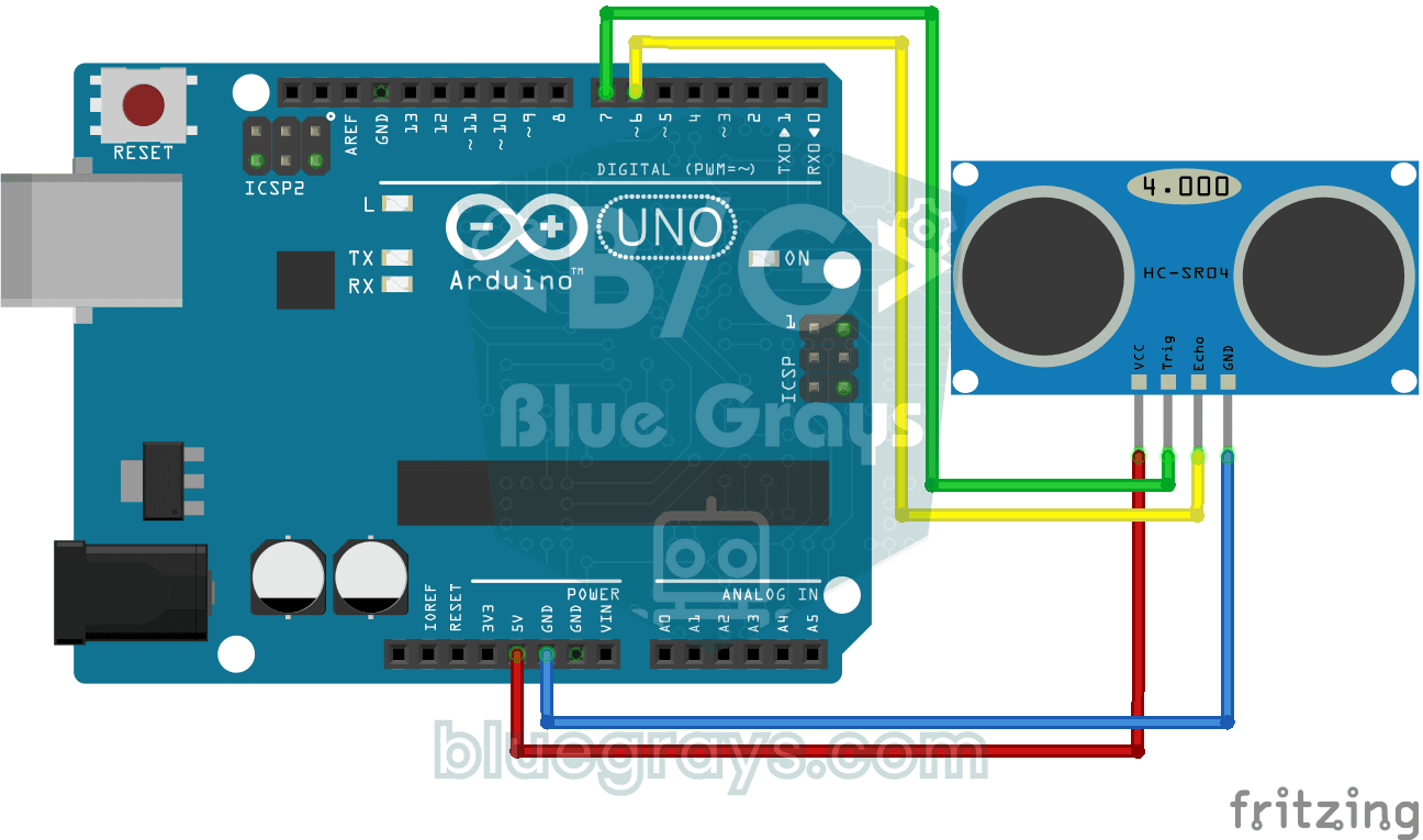
HC-SR04 Distance Measurement (Serial Display)
The HC-SR04 sensor works just like a bat finding its way in the dark: it sends out a sound you cannot hear, listens for the echo and measures how far away the object in front of it is. The Arduino wri
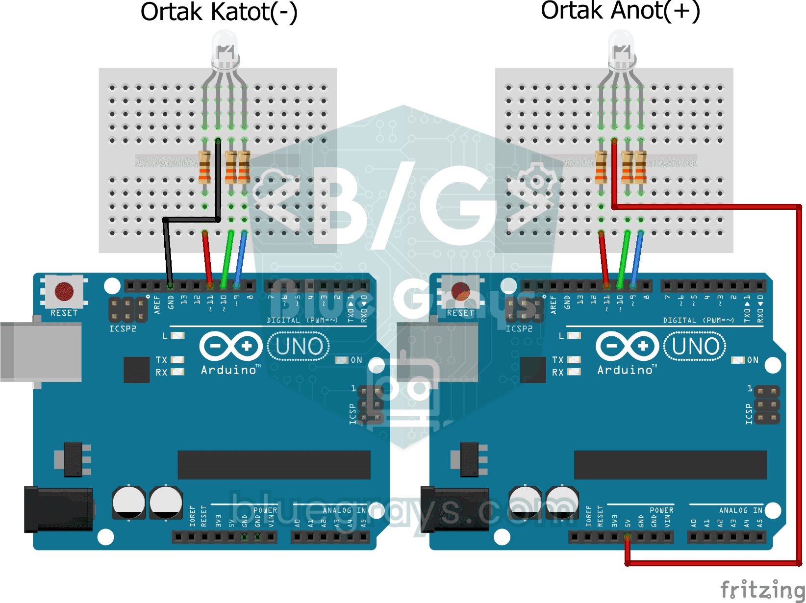
Smooth Color Transition with RGB Led
A single RGB LED drifts slowly from red to green, green to blue and back to red, looping through the rainbow without ever stopping. Each fade takes about two and a half seconds, and the yellow, turquo
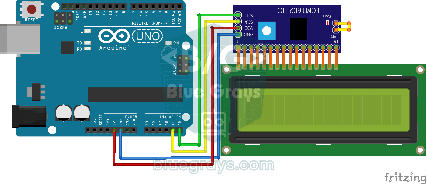
Using LCD Screen with I2C
Give your Arduino its own screen and make it write its first message. The two-line LCD screen hooks up with just a few wires; a greeting appears on the top line, then a second message on the bottom li
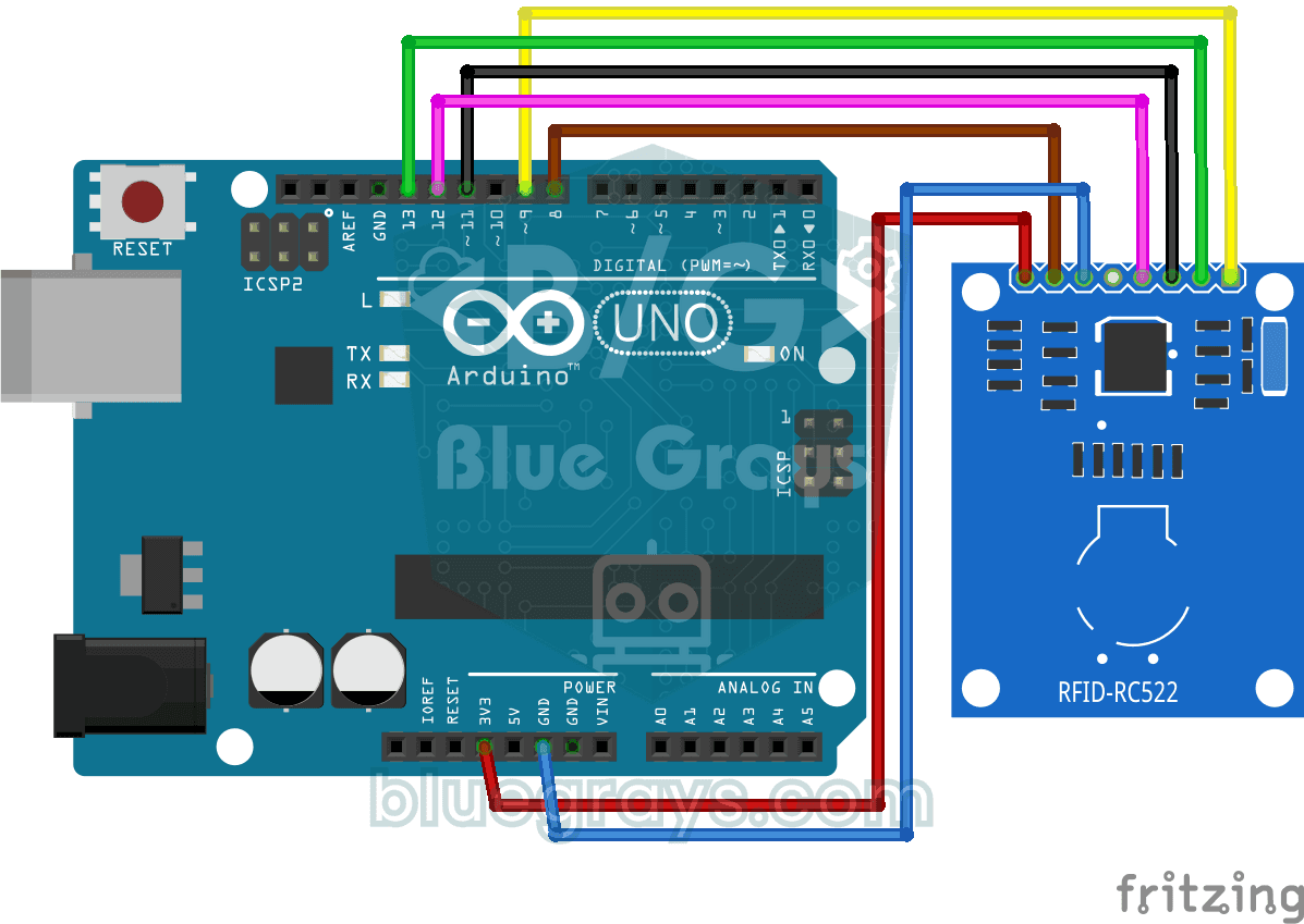
RFID Value Reading
Your building key fob or access card hides a secret ID number, and this project reads it. Hold the card near the RFID reader and the Arduino writes the card's number to your computer screen. The first
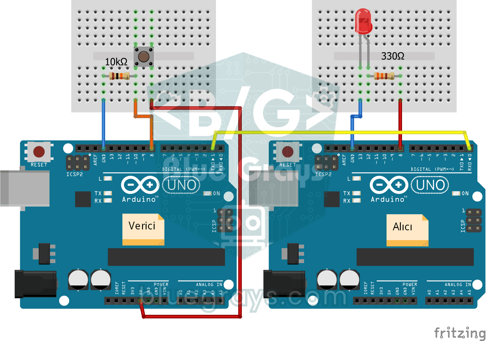
One-Way Communication Between 2 Arduinos
You get two Arduinos talking over a single wire: press the button on one and the LED on the other lights up, press it again and it goes off. The sending board reports the button press with a short mes