
How to Power Arduino with a Battery: 9V, AA, 18650 and Vin Pin
How to power Arduino with a battery: USB vs DC jack (7–12 V), Vin and 5V pins, 9V, AA and 18650 options, separate servo power and battery life math.
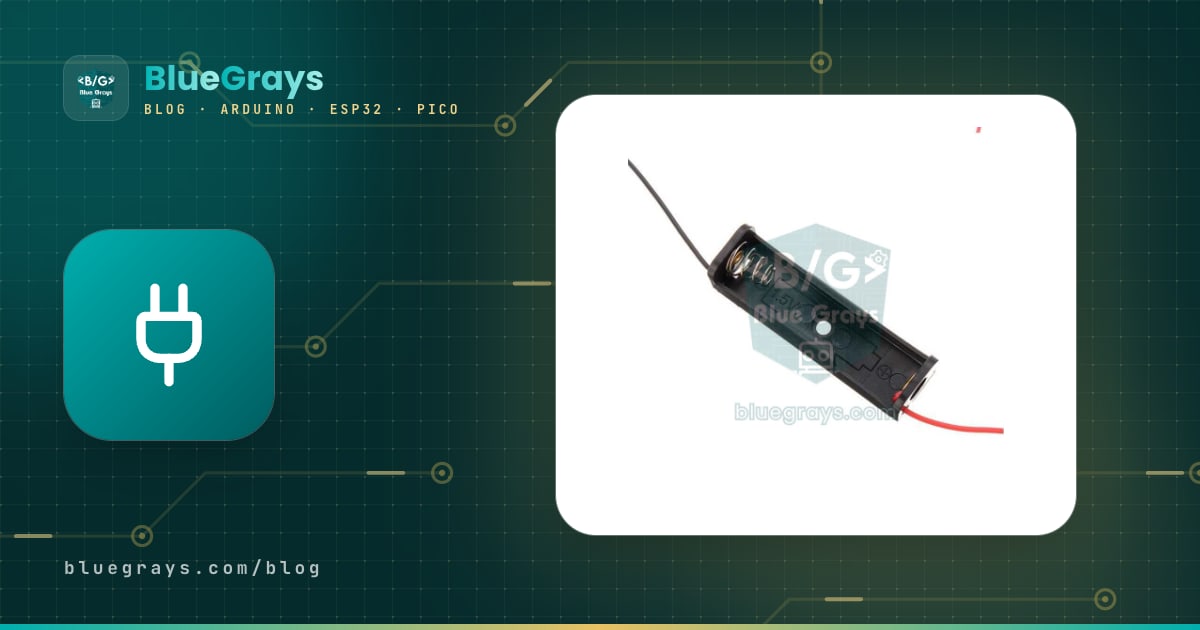
Powering an Arduino with a battery is the first step to freeing your project from the computer's USB cable and turning it into a robot car, a garden sensor or a device you carry in your pocket. The short answer: the safest way to run an Arduino Uno on batteries is to connect a 7–12 V pack (6×AA or two 18650 cells in series) to the DC barrel jack or the Vin pin, or to plug a power bank into the USB port. The 5V pin should only be used with a clean 5 V source that you have measured and adjusted, because this pin bypasses the board's regulator and protection completely.
Bad power is behind many of the mysterious problems beginners run into: a board that resets whenever the servo moves, a 9V battery that's dead in a few hours, a power bank that switches off after a few seconds, or a regulator too hot to touch. In this guide you'll learn every input you can use to power an Arduino, which battery goes where, why motors need their own supply, and how to calculate current draw and runtime. At the end we'll also look at how powering an ESP32 and a Raspberry Pi Pico from batteries differs.
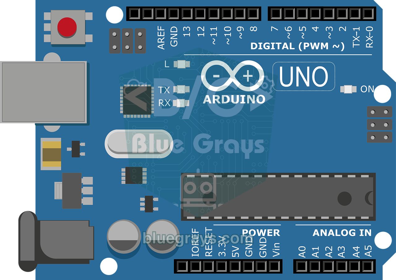
5 ways to power an Arduino
There are two separate power paths inside an Arduino Uno. The 5 V coming from USB passes through a 500 mA self-resetting fuse (polyfuse) and a small MOSFET switch, then goes straight to the board's 5 V rail. The voltage from the DC jack first goes through a reverse-polarity protection diode, appears on the Vin pin at that point, and is then brought down to 5 V by an LDO regulator from the 1117 family. The 3.3 V is produced from that 5 V rail by a second, smaller regulator. A comparator on the board watches Vin: once Vin goes above about 6.6 V, it automatically disconnects the USB supply, so the sources don't fight each other even when the adapter and USB are plugged in at the same time.
| Input | Voltage | Protection | When to use it |
|---|---|---|---|
| USB (type B) | 5 V | 500 mA polyfuse | Bench development, phone charger, power bank |
| DC jack (5.5×2.1 mm, centre positive) | 7–12 V recommended (limit 6–20 V) | Reverse-polarity diode + 5 V regulator | Wall adapter, 6×AA, 2S Li-ion pack |
| Vin pin | 7–12 V | Regulator yes, no reverse-polarity protection | Battery holder leads, shields |
| 5V pin | Measured 4.8–5.2 V | No protection at all | Adjusted buck/boost output, regulated 5 V source |
| 3.3V pin | Output only | None | 3.3 V sensors up to 50 mA |
USB power: the 500 mA limit
USB is the easiest and best-protected way to power an Arduino. A computer's USB 2.0 port supplies at most 500 mA; the Uno's polyfuse heats up and cuts the circuit when the total current goes above that, then reconnects on its own once it cools down. The board itself uses about 45–50 mA, which leaves roughly 400 mA for your sensors, LEDs and modules to share. A phone charger or a power bank can use the same USB port; the only difference is that the voltage can drop to 4.6 V on thin, long cables. While the board runs from USB, every milliamp you draw from the 5V pin comes out of that 500 mA budget. That's why hanging a servo or an LED strip on USB power trips the fuse, and the computer's port may also cut the connection to protect itself.
DC jack and Vin pin: why 7–12 V?
The board's 5 V regulator is a linear LDO, and it needs about 1–1.2 V more at its input than at its output to work properly. Add the 0.7–1 V drop of the protection diode on the jack, and you need at least 7 V at the jack for a solid 5 V. With a 6 V source the 5 V rail sinks to 4.2–4.5 V; the board may look like it's working, but analog readings drift and modules behave strangely. At the top end the problem is heat: a linear regulator turns the extra voltage into heat. The power it burns is P = (Vin − 5 V) × I. As a rule, don't make the regulator dissipate more than 1 W; at that point the small SOT-223 package gets too hot to touch and eventually shuts itself down.
| Vin voltage | Heat at 100 mA | Heat at 300 mA | Verdict |
|---|---|---|---|
| 7 V | 0.2 W | 0.6 W | Most efficient range |
| 9 V | 0.4 W | 1.2 W | Borderline at 300 mA |
| 12 V | 0.7 W | 2.1 W | Light loads only |
| 20 V | 1.5 W | 4.5 W | Not recommended, regulator overheats |
The Vin pin is both an input and an output. When you power the board through the jack, Vin carries the jack voltage minus about 0.7–1 V, so you can power a small 9–12 V load from it. But since there's a 1 A protection diode in the current path, big loads such as motors should be fed directly from the source, not from Vin. When you connect a battery holder to the Vin pin, that protection diode is bypassed: the regulator still works, but if you swap plus and minus nothing protects the board. On the newer Uno R4 Minima and R4 WiFi, the jack and Vin accept 6–24 V and use a switching (buck) converter instead of a linear regulator, so they don't overheat even at 12 V. For details, see Arduino Uno R4.
5V pin: when is it safe to bypass the regulator?
The 5V pin is wired directly to the supply rail of the ATmega328P and the other chips on the board. Powering through this pin skips the regulator, the reverse-polarity diode and the USB fuse. That's why Arduino's own documentation doesn't recommend powering through the 5V and 3.3V pins. Done right, though, it has advantages: there's no regulator drop or heat loss, so the battery lasts longer and you can give your modules more current. There's just one condition: the source must be regulated and measured. The ATmega328P is designed to run at up to 5.5 V, and 6 V is its absolute maximum; even a brief moment above that can damage the chip for good.
- Measure first: check the source's output with a multimeter before connecting it to the Arduino; it should be between 4.8 and 5.2 V.
- No raw batteries: fresh 4×AA alkaline cells reach 6.4 V and exceed the limit. Only connect the output of a regulator, buck or boost module to the 5V pin.
- Careful with USB at the same time: if you plug in USB while powering through the 5V pin, two 5 V sources get tied together through the board; disconnecting the external supply while you upload is the safest option.
- Add a capacitor: putting a 100–470 µF electrolytic capacitor on the external 5 V line near the board smooths out dips during sudden current draws (what is a capacitor?).
- Ready-made options: 7805-based regulator modules (7805 voltage regulator), an LM2596 set to 5.0 V, or the MB102 power module for breadboards all give a clean 5 V.
3.3V pin: how much current can you draw?
The Uno's 3.3V pin isn't a power input; it's the output of a small regulator, and its official limit is 50 mA. That's enough for modules that stay within a few tens of milliamps, such as a BME280, an MPU6050 or an RC522 RFID reader. Modules with high peak currents push it too far, though: the nRF24L01+PA+LNA with an antenna goes above 100 mA while transmitting, the ESP-01 Wi-Fi module draws peaks of several hundred milliamps, and the SIM800L wants bursts of up to 2 A. For the nRF24L01+PA+LNA and the ESP-01, use a separate AMS1117 3.3 V regulator module fed from the 5 V rail. The SIM800L, however, runs on 3.4–4.4 V rather than 3.3 V and exceeds the AMS1117's 1 A limit; power it from a single Li-ion cell or from a buck module set to 4.0 V that can deliver at least 2 A. On the Arduino Nano and its clones the 3.3V pin is often supplied from inside the USB-serial chip and is even weaker than on the Uno, so a separate regulator is the safer choice there too. You'll find more on powering wireless modules in the nRF24L01 guide.
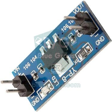
Battery options: 9V, AA, 18650 and power banks
| Battery | Voltage | Capacity | Connect to | Runtime with an Uno (~50 mA) |
|---|---|---|---|---|
| 9V alkaline | 9 V (drops to 7 V quickly under load) | 400–600 mAh | DC jack / Vin | 6–8 hours |
| 6×AA alkaline | 9 V | 2000–2500 mAh | DC jack / Vin | ~30 hours |
| 4×AA alkaline | 6 V (6.4 V fresh) | 2000–2500 mAh | Not recommended | Too low for the jack, too high for the 5V pin |
| 3×AA alkaline | 4.5 V | 2000–2500 mAh | 5V pin | ~1 day (unstable near the end) |
| 1×18650 + 5 V boost | 3.0–4.2 V → 5 V | 2000–3500 mAh | USB or 5V pin | ~30 hours (3000 mAh) |
| 2×18650 in series (2S) | 7.4 V (6.0–8.4 V) | 2000–3500 mAh | DC jack / Vin | ~2 days (3000 mAh) |
| 10000 mAh power bank | 5 V (USB) | ~6000 mAh (at 5 V) | USB | ~5 days (if it stays on) |
The classic 9V battery is the most recommended option thanks to its snap-on lead with a barrel plug, but it's also the least efficient. It contains six small cells, so its capacity is only around 400–600 mAh and its internal resistance is high; add a servo or a few LEDs to the Uno's 50 mA and the voltage soon falls below 7 V and the board starts resetting. On a board with a linear regulator, the battery's mAh rating directly sets the runtime, and the extra volts just turn into heat. That's why a 6×AA holder, which gives the same 9 V, lasts about four times longer than a 9V battery. We explain capacity units in detail in What does mAh mean?.
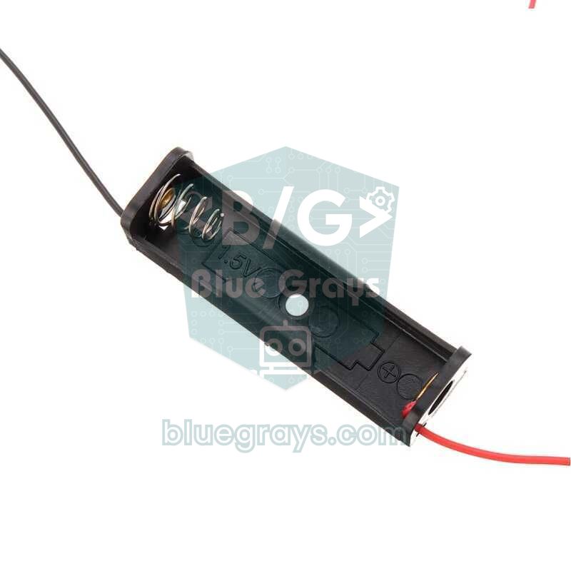
AA batteries are cheap and available everywhere, but you need to pick the right number of cells. The most common mistake is using 4×AA: 6 V isn't enough for the jack, because after the diode and regulator drops only about 4.2 V reaches the 5 V rail, while connecting the same pack to the 5V pin means 6.4 V with fresh cells, which exceeds the limit. The right combinations are a 6×AA (9 V) pack into the DC jack, and a 3×AA (4.5 V) pack straight into the 5V pin. An Uno running at 16 MHz on 3×AA starts to become unstable once each cell drops below 1.25 V, so you can't use the full capacity. Rechargeable NiMH cells give 1.2 V each, so 4×NiMH (4.8 V) is also a popular choice for the 5V pin, but freshly charged cells can exceed 5.5 V for the first few minutes.
18650 Li-ion cells and boost converters
The 18650 is a rechargeable lithium-ion cell, 18 mm in diameter and 65 mm long, used in laptop batteries and power banks. Its nominal voltage is 3.7 V; it measures 4.2 V when full and about 3.0 V when empty. Its real capacity is between 2000 and 3500 mAh; cells labelled 6800 or 9900 mAh are almost always fake. A single 18650 can be used with an Arduino in two ways: boosting 3.7 V to 5 V with a boost converter (for example an MT3608 module or a ready-made 18650 power bank board) and feeding USB or the 5V pin, or connecting two cells in series and plugging the 2S (7.4 V) pack into the DC jack. The second is the most balanced option for the Uno: starting at 8.4 V, the voltage stays in the regulator's comfortable range until it falls to 3.5 V per cell (7 V total). When you use a boost converter, remember that the current drawn from the battery is higher than at the output: a circuit that needs 200 mA at 5 V draws about 307 mA from a 3.7 V cell at 88 percent efficiency.
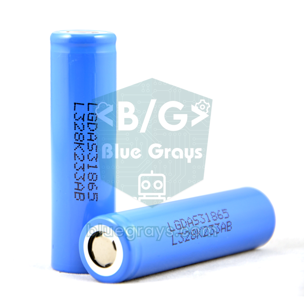
- Protection is a must: discharging a Li-ion cell below 3.0 V shortens its life and can be dangerous. Use protected cells or a protection board (BMS).
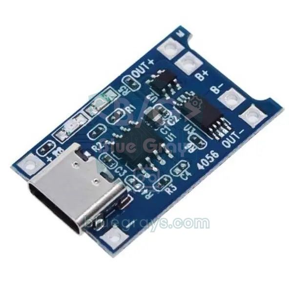
- TP4056 is for single cells: the TP4056 module only charges one cell (1S) to 4.2 V. Never charge a 2S series pack with a TP4056; use a 2S BMS charging circuit or a balance charger. Wiring details are in TP4056 charging module.
- Watch out for short circuits: an 18650 can deliver tens of amps into a short; don't leave bare wires, and add a fuse and a switch to the battery line.
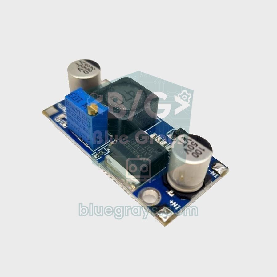
- Boost setting: don't connect adjustable modules such as the MT3608 to the Arduino before setting their output to 5.0 V.
- Don't mix cells: in a series pack, use cells of the same brand, capacity and charge level.
Why does my power bank switch off by itself?
A power bank is a ready-made pack with lithium cells, a charger, protection and a 5 V boost inside, so it's the least effort way to run an Arduino on batteries: just plug in the USB cable. However, most power banks monitor the output current so they can shut down when your phone is full, and they cut the output within 10–60 seconds once the current drops below 50–100 mA. A Nano drawing 20 mA or an Uno drawing 50 mA stays below that threshold, so the board runs for a while and then quietly turns off. There are two ways around it: choose a power bank with a low-current mode (on some models you enable it by pressing the button twice), or make the Arduino draw a short load at regular intervals. For the second method, connect a 47 Ω, 1 W resistor from the 5V rail to the collector of an NPN transistor (BC337 or 2N2222), the emitter to GND, and the base to pin D7 through a 1 kΩ resistor. When the transistor switches on, the resistor draws about 5 V / 47 Ω ≈ 106 mA and the power bank sees a load. You can check the values yourself with the Ohm's law calculator.
1// Powerbank uyanık tutma / powerbank keep-alive
2// D7 -> 1 kΩ -> NPN beyzi, kolektör -> 47 Ω -> 5V / D7 -> 1 kΩ -> NPN base, collector -> 47 Ω -> 5V
3const int LOAD_PIN = 7;
4const unsigned long PERIOD_MS = 8000;  // her 8 saniyede bir / every 8 seconds
5const unsigned long PULSE_MS = 300;    // 300 ms yük / 300 ms of load
6
7unsigned long pulseStart = 0;
8bool loadOn = false;
9
10void setup() {
11  pinMode(LOAD_PIN, OUTPUT);
12  digitalWrite(LOAD_PIN, LOW);
13}
14
15void loop() {
16  unsigned long now = millis();
17  if (!loadOn && now - pulseStart >= PERIOD_MS) {
18    digitalWrite(LOAD_PIN, HIGH);   // ~106 mA çek / draw ~106 mA
19    loadOn = true;
20    pulseStart = now;
21  }
22  if (loadOn && now - pulseStart >= PULSE_MS) {
23    digitalWrite(LOAD_PIN, LOW);    // yükü kapat / switch the load off
24    loadOn = false;
25  }
26  // projenin kodu burada, delay() kullanmadan / your project code here, without delay()
27}
Because the code uses millis() instead of delay(), it doesn't block the rest of your project; we explain this approach in detail in millis() vs delay(). Drawing 106 mA for 300 ms every 8 seconds adds only about 4 mA on average. If your power bank still switches off, shorten the period to 5 seconds or lengthen the pulse to 500 ms; every model uses a different threshold and timeout.
Separate power for motors and servos, common GND
Motors and servos are the loads that cause the most trouble when you power an Arduino from batteries. A servo draws a current spike of several hundred milliamps the moment it starts moving, and DC motors pull several times their normal current when starting or when stalled. That spike can briefly collapse the 5 V rail; if the voltage falls far enough, the ATmega328P's brown-out detection kicks in and the board resets itself. On top of that, brush noise from motors corrupts sensor readings. The rule is simple: power at most one small servo from the Arduino's 5V pin, and run every other motor from a separate supply. For how servos and DC motors work, see servo motor and DC motor control with the L298N.
| Load | Normal current | Peak current | Recommended supply |
|---|---|---|---|
| SG90 micro servo | 100–250 mA | 0.5 A or more (when stalled) | One: Arduino 5V; more: separate 5 V |
| MG996R servo | 0.5–0.9 A | Up to 2.5 A | Separate 5–6 V, at least 2–3 A per servo |
| TT gear DC motor | 70–250 mA | ~1 A (start-up, stall) | L298N or L9110S + separate 6–9 V pack |
| 28BYJ-48 stepper | ~240 mA | ~240 mA | Separate 5 V to the ULN2003 board |
| WS2812B LED (each) | ~20 mA (medium brightness) | 60 mA (full white) | Separate 5 V above 30 LEDs |
| Mini submersible water pump | 100–200 mA | Several times more at start-up | Relay or MOSFET + separate supply |
- Choose a separate supply for the motors: 5–6 V for servos (4×AA NiMH or an LM2596 set to 5–6 V), and a pack that matches the motor voltage for DC motors (for example 2S 18650).
- Connect the supply's positive only to the servos' red wires or to the motor driver's power input; don't connect it to the Arduino's 5V pin.
- Power the Arduino through its own input: you can connect the same 2S pack to the DC jack too, as long as the motor current doesn't flow through the Arduino's regulator.
- Connect the supply's negative (GND) to the Arduino's GND pin. Without a common GND the control signal won't work.
- Connect the servo's orange or yellow signal wire to one of the Arduino's digital pins (for example D9); the Servo library also works on pins without the PWM mark.
- Add a 470–1000 µF electrolytic capacitor across the servo supply, close to the servos; mind the polarity.
- If you're using an L298N, feed the motor supply into the 12V terminal; if the supply is above 12 V, remove the 5V-EN jumper and power the Arduino from its own source.
How do you calculate current and runtime?
The real question in a battery-powered project is "how long will it last?". The basic formula is simple: Runtime (hours) = Battery capacity (mAh) × 0.85 / Average current (mA). The 0.85 factor accounts for the fact that a battery never delivers its full rated capacity: capacity drops at high currents and in the cold, the circuit stops before the battery is completely flat, and converters add losses. For batteries whose voltage sags early, such as a 9V, using 0.7 is more realistic. If your project spends most of its time asleep, work out the average current first: Average current = (Active current × active time + Sleep current × sleep time) / total time. Instead of doing this by hand, you can use the battery life calculator; enter the capacity, awake and sleep currents and the wake interval, and it gives you the runtime in hours, days or months.
| Scenario | Average current | Battery | Approx. runtime |
|---|---|---|---|
| Uno + I2C LCD, always on | ~75 mA | 2S 18650 (3000 mAh) | ~34 hours |
| Nano + sensor + power bank keep-alive | ~29 mA (25 + 4) | 10000 mAh power bank (~6000 mAh, 5 V) | ~7 days |
| ESP32 module: awake 5 s every 10 minutes (120 mA), 150 µA asleep | ~1.15 mA | 18650 (3000 mAh) | ~3 months |
| Same code, dev board drawing 5 mA asleep | ~6 mA | 18650 (3000 mAh) | ~18 days |
| Pico + MicroPython, always on | ~25 mA | 3×AA NiMH (2000 mAh) | ~68 hours |
Measuring always beats guessing. Switch your multimeter to the current (mA) range and connect it in series between the battery and the circuit to see the real consumption; we show how in how to use a multimeter. If the reading is higher than you expected, look at the board's own consumption first: on the Uno, the USB-serial chip (ATmega16U2), the power LED and the regulator draw more than 30 mA even while the ATmega328P sleeps. That's why projects that need long battery life favour boards without a USB chip, such as the Arduino Pro Mini; a Pro Mini with its power LED and regulator removed gets down to microamps in sleep mode.
Step by step: get your project running on batteries
- While the project runs from USB, measure its average and peak current with a multimeter; measure it while the servo or motor is moving, too.
- Separate high-current loads such as motors, servos and LED strips, and plan a separate supply for them.
- Choose the board's input: for the Uno, a 7–12 V pack into the DC jack or regulated 5 V into USB or the 5V pin; for the Pico, 1.8–5.5 V into VSYS.
- Calculate the capacity you need for the runtime you want, or use the battery life calculator.
- Add an on/off switch to the battery's positive line; make sure Li-ion packs have a protection board (BMS).
- Upload the code over USB, then unplug USB and test on batteries; check the voltage on the 5V pin with a multimeter while the servo moves.
- Monitor the battery voltage in code and warn when it drops below a set value (code below).
Measuring the battery voltage with Arduino
Instead of guessing when the battery will run out, you can measure its voltage. The Arduino's analog inputs can read at most 5 V, so you can't connect a 2S pack that reaches 8.4 V straight to A0; you need a voltage divider. Two resistors of 100 kΩ and 10 kΩ divide the voltage by 11: 8.4 V becomes about 0.76 V at A0. Because the board's 5 V rail can drift as the battery weakens, it's more accurate to measure against the internal 1.1 V reference, which doesn't depend on the supply voltage. You can pick resistor values for your own pack with the voltage divider calculator and read more in voltage divider.
1// 2S Li-ion paket gerilimini ölçme / measuring a 2S Li-ion pack voltage
2// Pil+ -> 100k -> A0 -> 10k -> GND / pack+ -> 100k -> A0 -> 10k -> GND
3const int BAT_PIN = A0;
4const int LED_PIN = 13;      // pil zayıf uyarısı / low-battery warning
5const float R1 = 100000.0;   // üst direnç / top resistor
6const float R2 = 10000.0;    // alt direnç / bottom resistor
7const float VREF = 1.1;      // dahili referans, multimetreyle düzelt / internal reference, calibrate with a multimeter
8const float LOW_V = 6.6;     // 2S için alt sınır (3,3 V/hücre) / low limit for 2S (3.3 V per cell)
9
10void setup() {
11  Serial.begin(9600);
12  pinMode(LED_PIN, OUTPUT);
13  analogReference(INTERNAL);   // 1,1 V referans (Uno/Nano) / 1.1 V reference (Uno/Nano)
14  analogRead(BAT_PIN);         // ilk ölçümü at / discard the first reading
15  delay(10);
16}
17
18void loop() {
19  long sum = 0;
20  for (int i = 0; i < 16; i++) {   // 16 ölçümün ortalaması / average of 16 readings
21    sum += analogRead(BAT_PIN);
22    delay(2);
23  }
24  float pinV = (sum / 16.0) * VREF / 1024.0;
25  float batV = pinV * (R1 + R2) / R2;
26
27  Serial.print("Pil / Battery: ");
28  Serial.print(batV, 2);
29  Serial.println(" V");
30
31  digitalWrite(LED_PIN, batV < LOW_V ? HIGH : LOW);   // zayıfsa LED yanar / LED on when low
32  delay(2000);
33}
Connect the top of the divider to the battery's positive after the on/off switch, so the divider doesn't drain the battery while the device is off. The internal 1.1 V reference can vary by about ±10% from chip to chip: compare the battery voltage you measure with a multimeter against the Serial Monitor and correct VREF (for example to 1.08). The divider draws about 76 µA all the time, which has practically no effect on battery life. The code is for the Uno and Nano; on the Mega the reference is called INTERNAL1V1. The 6.6 V threshold corresponds to 3.3 V per cell; at that point the cells are almost empty, and going below 3.0 V per cell damages them. If the pack feeds the DC jack, the 5 V rail starts to sag at around 7 V, so setting LOW_V to 7.0 also makes sense.
Powering an ESP32 from batteries
ESP32 development boards run at 3.3 V and can be powered in three ways: the USB port, the 5V pin (VIN on some boards) or directly through the 3V3 pin. Espressif clearly states that these options must not be used at the same time and that only one should be chosen. Voltage applied to the 5V pin goes through the board's 3.3 V LDO regulator (an AMS1117 on most clones), while the 3V3 pin only accepts regulated 3.0–3.6 V. When transmitting over Wi-Fi the ESP32 draws peaks of up to 240 mA, so it needs a supply that can deliver at least 500 mA; otherwise it resets with the "Brownout detector was triggered" error (details in brownout error). Don't connect a single 18650 directly to the 3V3 pin: at 4.2 V when full, it exceeds the limit. The 5V pin isn't a good fit either, because the AMS1117 needs a drop of about 1.1 V, so as the cell voltage falls the output sinks below 3.3 V. The right options are an 18650 with a 5 V boost into the 5V pin, a low-dropout 3.3 V regulator that can supply at least 500 mA, or an ESP32 board with a built-in Li-ion charger. What really decides battery life, though, is the ESP32 spending most of its time in deep sleep; the chip draws about 10 µA in this mode, but the USB-serial chip, LED and regulator on dev boards can push that into the milliamp range. That's where the gap between 3 months and 18 days in the table above comes from; for details see ESP32 deep sleep.
1// ESP32: 18650 gerilimini ölç, sonra derin uykuya geç / measure the 18650, then deep sleep
2// Pil+ -> 100k -> GPIO34 -> 100k -> GND / cell+ -> 100k -> GPIO34 -> 100k -> GND
3const int BAT_PIN = 34;                         // yalnız giriş, ADC1 / input-only, ADC1
4const uint64_t SLEEP_US = 60ULL * 1000000ULL;   // 60 saniye / 60 seconds
5
6void setup() {
7  Serial.begin(115200);
8  uint32_t mv = 0;
9  for (int i = 0; i < 16; i++) {
10    mv += analogReadMilliVolts(BAT_PIN);        // kalibre milivolt / calibrated millivolts
11  }
12  float batV = (mv / 16.0) * 2.0 / 1000.0;      // bölücü yarıya indirir / the divider halves it
13  Serial.printf("Pil / Battery: %.2f V\n", batV);
14
15  if (batV < 3.3) {
16    Serial.println("Pil zayif / Battery low");  // işi atla, pili koru / skip the work, protect the cell
17  } else {
18    // sensörü oku, Wi-Fi ile gönder / read the sensor, send over Wi-Fi
19  }
20
21  esp_sleep_enable_timer_wakeup(SLEEP_US);      // 60 sn sonra uyan / wake up after 60 s
22  Serial.flush();
23  esp_deep_sleep_start();                       // loop() hiç çalışmaz / loop() never runs
24}
25
26void loop() {
27}
On every wake-up the code measures the battery voltage, does its work and goes back to sleep with a 60-second timer; since an ESP32 waking from deep sleep restarts the program from the beginning, loop() never runs. GPIO 34 is an input-only ADC1 pin and works while Wi-Fi is on, whereas ADC2 pins can't be used together with Wi-Fi. analogReadMilliVolts() uses the chip's factory calibration to return millivolts directly. The 100 kΩ + 100 kΩ divider brings 4.2 V down to 2.1 V and draws only 21 µA; if the reading is noisy, add a 100 nF capacitor between GPIO 34 and GND. For your first steps with the ESP32, What is the ESP32? is a good place to start.
Powering a Raspberry Pi Pico from batteries
The Raspberry Pi Pico is one of the easiest boards to run on batteries, because instead of a linear regulator it has a buck-boost switching regulator. Give the VSYS pin anything between 1.8 and 5.5 V and the board efficiently converts it to 3.3 V; it keeps working even when the input falls below 3.3 V. This means 2 or 3 AA cells, a single 18650 or a single-cell LiPo can be connected directly between VSYS and GND with no extra module. The one thing to watch is using it together with USB: the USB 5 V (VBUS) is connected to VSYS through a Schottky diode, so if the battery is wired straight to VSYS and you plug in USB, USB tries to push current into the battery. The solution Raspberry Pi recommends is to connect the battery to VSYS through its own Schottky diode (for example a 1N5817). The 3V3 pin can supply at most about 300 mA to external circuits, and pulling the 3V3_EN pin to GND turns off the regulator and therefore the whole board. For an overview of the board, see What is the Raspberry Pi Pico?.
1from machine import ADC, Pin
2import time
3
4vsys = ADC(29)            # VSYS/3 ölçer (Pico) / measures VSYS/3 (Pico)
5usb = Pin(24, Pin.IN)     # USB takılıysa 1 / 1 when USB is connected
6CONV = 3.3 / 65535        # ham değeri volta çevir / raw value to volts
7
8while True:
9    total = 0
10    for _ in range(16):   # 16 ölçümün ortalaması / average of 16 readings
11        total += vsys.read_u16()
12    volts = total / 16 * CONV * 3   # kart içindeki bölücü 3'e böler / on-board divider divides by 3
13    source = "USB" if usb.value() else "Pil / Battery"
14    print("{}: VSYS = {:.2f} V".format(source, volts))
15    if not usb.value() and volts < 3.3:   # 3xAA ya da 18650 için alt sınır / low limit for 3xAA or a 18650
16        print("Pil zayif! / Battery low!")
17    time.sleep(5)
On the Pico, GP29 measures one third of VSYS through an on-board divider, while GP24 reads 1 when USB is connected. So without any extra parts you can find out both the battery voltage and whether the board is running from USB or from the battery. If you connected the battery through a Schottky diode as recommended, VSYS reads about 0.2–0.3 V below the battery voltage. The reading assumes the ADC reference is 3.3 V; thanks to the buck-boost regulator, that reference stays steady even as the battery weakens. On the Pico W, GP29 and GP24 are shared with the wireless chip, so this code won't work as is; there, the USB status is read with Pin("WL_GPIO2"). To extend battery life, use machine.lightsleep() instead of time.sleep() between readings.
Battery-powered project ideas
- Bluetooth-controlled robot car: power both the motors and the Arduino from a 2S 18650 pack; details in building an Arduino car.
- Obstacle-avoiding robot: prevent resets by powering the motors through the L298N on a separate line and the Arduino from the DC jack (obstacle-avoiding robot).
- Voltmeter with battery gauge: show the value you measure through a voltage divider on an LCD (building an Arduino voltmeter).
- Garden moisture station: keep an ESP32 in deep sleep, measure soil moisture once an hour and run it for months on a single 18650.
- Portable GPS logger: record your hiking route with a NEO-6M GPS and a power bank.
- Battery-powered Pico night light: a Pico fed from 3×AA cells through VSYS switches on LEDs when the room gets dark.
Common mistakes and how to fix them
| Symptom | Likely cause | Fix |
|---|---|---|
| The board resets when the servo moves | Servo current collapses the 5 V rail | Power the servo separately, add a common GND and a 470–1000 µF capacitor |
| The 9V battery is dead in a few hours | A 9V battery holds only 400–600 mAh | Use a 6×AA or 2S 18650 pack |
| The power bank switches off in 10–60 seconds | Current is below the auto-off threshold | Low-current mode or a keep-alive pulse |
| The regulator gets very hot | High input voltage and high current | Lower the input to 7–9 V or make the 5 V with a buck module |
| Analog readings drift on battery power | Input below 7 V, the 5 V rail sags | Raise the pack voltage or use the internal 1.1 V reference |
| The board gets hot or won't turn on | Reverse polarity, or more than 5.5 V on the 5V pin | Disconnect the source, check polarity and voltage with a multimeter |
| The ESP32 resets while connecting to Wi-Fi | The supply can't deliver the peak current (brownout) | Short, thick wires, a 470 µF capacitor, a stronger supply |
| On the Pico the battery warms up with USB plugged in | USB pushes current into the battery through VSYS | Add a Schottky diode to the battery line |
Good power is half of what makes a project run reliably: pick the right input, power motors separately, join the grounds and work out battery life from the start. When you're ready to build a battery-powered project, check out the Bluetooth-controlled L298N car, the obstacle-avoiding robot, the smart irrigation station, the digital voltmeter with LCD and the ESP32 deep sleep battery-saving projects in the BlueGrays app; each one walks you through the circuit diagram, the wiring and the code step by step.
Frequently asked questions
Can an Arduino run on a 9V battery?
Yes, a 9V battery can be connected to the Arduino Uno's DC jack or Vin pin, and the board runs comfortably in the 7–12 V range. However, a 9V alkaline battery holds only 400–600 mAh, so on its own it runs an Uno for about 6–8 hours, and much less once you add a servo or a motor. For long-running projects, 6×AA or two 18650 cells in series are a better choice.
Can I power an Arduino with a power bank?
Yes; just plug the power bank into the Arduino's USB port with a USB cable, and the board is protected by its USB fuse. The catch is that many power banks don't detect loads below 50–100 mA and switch their output off after a short time. You can choose a model with a low-current mode, or add a keep-alive circuit that makes the Arduino draw a short load every few seconds.
Can I power an Arduino with a 12V adapter?
Yes, 12 V is the top of the Uno's recommended 7–12 V range and is safe through the DC jack. But since the on-board linear regulator turns the extra 6–7 V into heat, it will overheat if you draw more than about 150 mA from the 5 V rail. If you need more current, use a 9 V adapter or make the 5 V with a separate buck module; the Uno R4 runs happily up to 24 V.
Can I power an Arduino through the 5V pin?
You can, but the 5V pin bypasses the board's regulator, reverse-polarity diode and USB fuse, so there's no protection at all. Only connect a regulated source that you've measured with a multimeter and that stays between 4.8 and 5.2 V (for example an LM2596 or boost module set to 5.0 V). A source above 5.5 V, or one connected the wrong way round, can destroy the ATmega328P instantly.
Can an Arduino run on a 3.7V Li-ion battery?
An Uno doesn't run reliably on 3.7 V directly: it's too low for the DC jack and not enough for the 5V pin. You need to boost a single cell to 5 V with a boost converter and feed USB or the 5V pin, or connect two cells in series and plug the 7.4 V pack into the DC jack. A 3.3 V Pro Mini (on its RAW pin) and a Raspberry Pi Pico (on VSYS), on the other hand, run comfortably straight from a single cell, and an ESP32 does too with a low-dropout 3.3 V regulator.
How long will an Arduino run on batteries?
You find the runtime by dividing capacity by average current: capacity (mAh) × 0.85 / average current (mA). For example, an Uno drawing 50 mA runs for about 50 hours on a 3000 mAh 2S 18650 pack. An ESP32 using deep sleep can last for months on the same capacity; the battery life calculator in BlueGrays also takes sleep current into account.
Projects to build after reading this
See all projects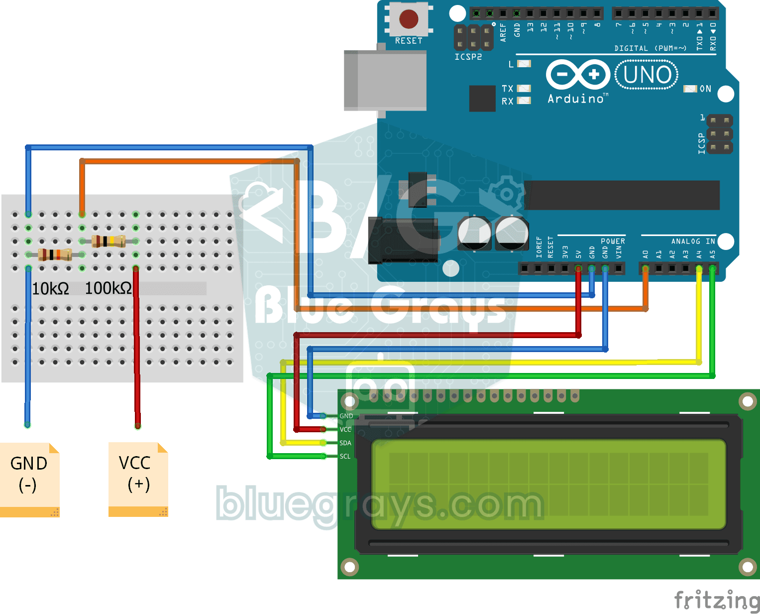
Digital Voltmeter with LCD Display
Find out how much voltage a battery or power adapter gives with a meter you built yourself. A divider made of two resistors brings high voltage down to a level the board can read, and the Arduino calc
Using a Servo Motor
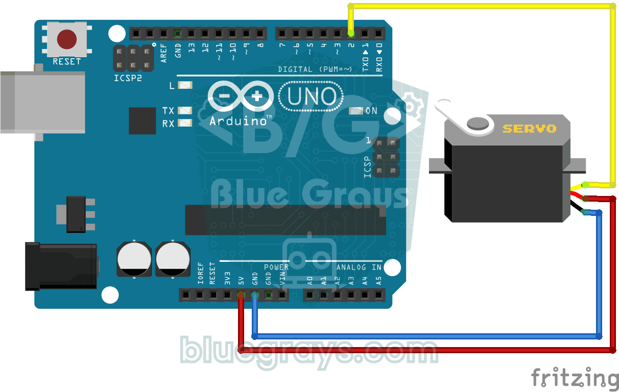
The arm of a small servo motor turns to three positions in turn: all the way to the start, right to the middle and all the way to the end, waiting two seconds at each stop. The Arduino tells the motor

Bluetooth Controlled Car with L298N
Turn your phone into a remote and drive your own robot car. The Arduino receives commands from a remote-control app on your phone through a Bluetooth module and spins the wheels with a motor driver; t

Obstacle Avoidance Robot
How about building a smart vehicle that finds its own way? The Obstacle Avoidance Robot constantly scans its surroundings thanks to the ultrasonic sensor in front of it. When it encounters an obstacle

Smart Irrigation Station
A gardener that waters your plants on its own, so they don't dry out while you're on vacation. A soil moisture sensor measures how wet the soil is; when it gets dry, the Arduino runs the water pump fo

ESP32 Deep Sleep — Battery Saving (OLED + RTC RAM Counter)
The ESP32's Deep Sleep mode reduces current consumption to ~10 µA by shutting down the CPU and most peripherals, making it critical for battery-powered IoT devices. In this project, we use three different wake-up sources: a timer (15 seconds), an external pin (EXT0 — button GPIO 33), and touch (T0/GPIO 4). Variables marked with RTC_DATA_ATTR are preserved during deep sleep—the boot counter, timer wake counter, and button wake counter are continuously tracked. On each wake-up, the SSD1306 OLED

ESP32 Servo Motor (Potentiometer Control)
In this project, we control an SG90 servo motor using a potentiometer. We adjust the servo angle by mapping the analog value read from the potentiometer to the 0–180-degree range. The ESP32Servo library generates servo signals on suitable output-capable GPIO pins of the ESP32; this project uses GPIO 18. This is a fundamental control method for robotic arms, camera gimbals, and automatic door mechanisms.