
Jumper Wires for Arduino: Types, AWG, Current and Testing
Jumper wires for Arduino: male-male, male-female and female-female types, AWG gauge and current, loose contacts, multimeter testing and crimping Dupont wires.
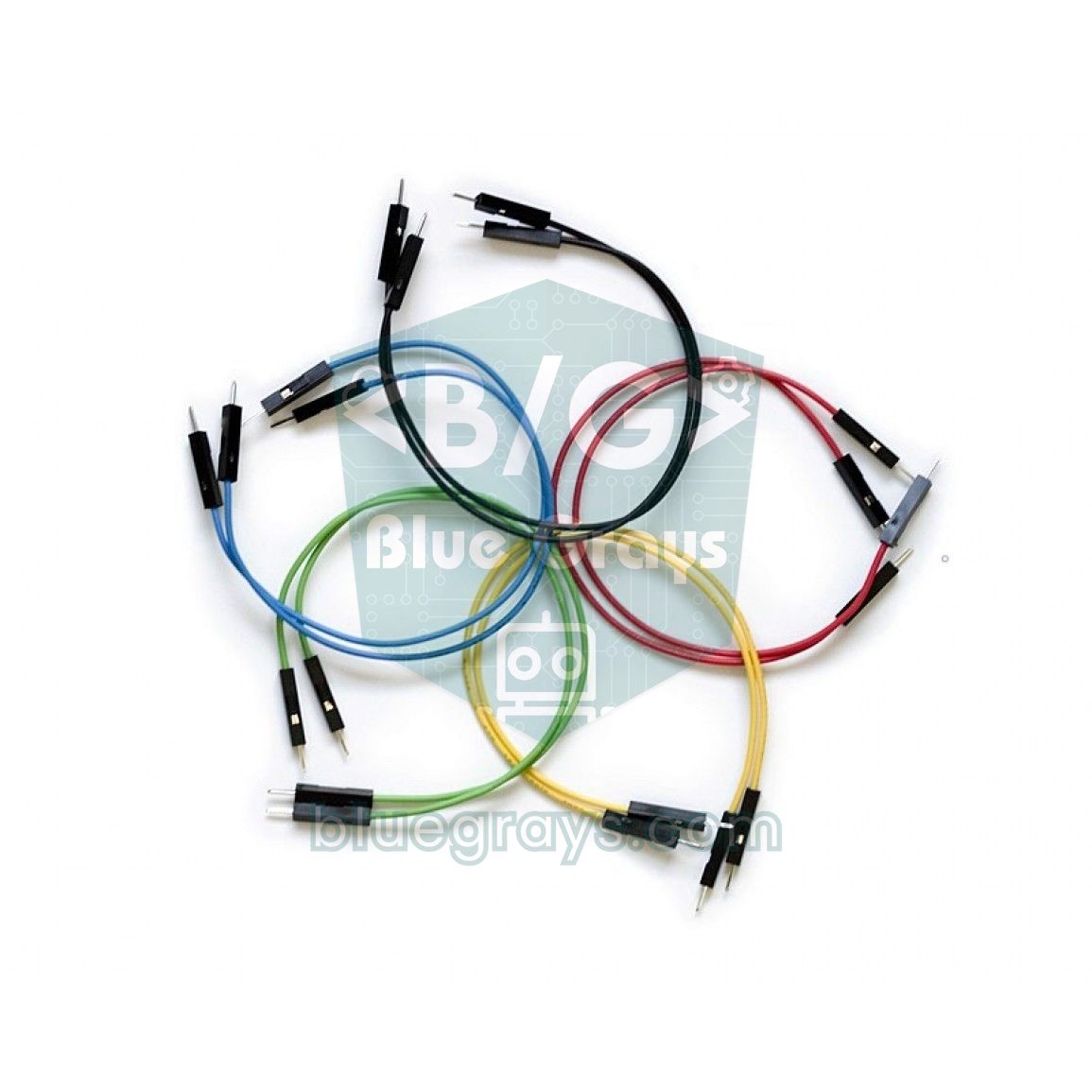
Jumper wires for Arduino are thin wires with 2.54 mm pitch Dupont connectors on both ends, used to connect a breadboard, an Arduino and sensor modules in seconds without soldering. In short, a jumper wire is a plug-in wire bridge for trying out, changing and taking apart a circuit. Depending on whether the ends are male (with a pin) or female (with a socket), there are three basic types, male-male, male-female and female-female, and each is designed for a different kind of connection.
They look like the cheapest part of the kit, yet a surprising share of beginner problems comes from them: a sensor that sometimes doesn't respond, an I2C display that appears and disappears, or a board that resets when you touch a wire. In this article you'll learn the types of jumper wires and which one to use for each connection, how much current each wire gauge (AWG) can carry, how to catch a loose contact or a broken wire with a multimeter and a small Arduino sketch, how to make your own Dupont wires, and how to lay out a breadboard for the Arduino Uno, ESP32 and Raspberry Pi Pico.
What is a jumper wire and what is it used for?
A jumper wire has three parts: a thin, flexible copper wire, a metal terminal crimped onto the end of the wire and a plastic housing around it. The terminal can be male, a pin about 0.6 mm thick that goes into a breadboard hole, or female, a spring socket that slides over a header pin. This connector system is commonly called Dupont. Because the pitch is 2.54 mm (0.1 inch), it fits all standard pin headers, breadboards, the Arduino's female headers and the male pins of modules. Jumper wires are usually sold as 40-wire colored ribbons in 10, 20 and 30 cm lengths, and you peel off as many as you need. Note that "jumper" means something else in electronics too: the small plastic cap that shorts two pins on boards like the L298N is also called a jumper (shunt). In this article, the jumper is the wire.
Types of jumper wires: male-male, male-female, female-female
| Type | Ends | Where is it used? | Example connection |
|---|---|---|---|
| Male-male (M-M) | Pins on both ends | Inside the breadboard and between the breadboard and the Arduino Uno's female headers | Uno 5V → breadboard + rail |
| Male-female (M-F) | A pin on one end, a socket on the other | Connecting a module with pins to the breadboard or the Uno | HC-SR04 male pins → Uno D9 and D10 |
| Female-female (F-F) | Sockets on both ends | Joining two male headers directly, without a breadboard | ESP32 pins → L298N IN1–IN4 |
| Solid-core breadboard wire | Stiff wire cut and bent into a U shape | Short, flat and tidy connections on the breadboard | Joining rails, connecting an LED to its resistor |
| Alligator clip lead | Spring clips | Temporary connections to batteries, multimeters and screw terminals | Trying a battery pack on the circuit |
For a first set we recommend one ribbon of each type (40 wires, 20 cm); male-male and male-female are the ones you run out of first. 20 cm is ideal for most desktop circuits. 30 cm wires are handy for reaching a distant sensor but make the circuit messy, and for connections inside the breadboard a solid-core jumper kit looks much tidier. We compare starter kit contents in Arduino starter kit.
Solid core or stranded? Copper or CCA?
Dupont jumper wires usually have a stranded conductor made of 7 or more fine strands: it's flexible and survives bending, but if the end is left bare the strands splay. Breadboard jumper wires, on the other hand, have a single thick solid-core wire: it goes straight into the hole and stays put, but it breaks if bent many times at the same point. Some cheap wires aren't pure copper but aluminum with a thin copper coating (CCA). CCA has about 50–60% more resistance than copper of the same gauge and breaks more easily. It's easy to spot: cut the end and scrape the wire; if it's silver inside, it's CCA. It's fine for signal lines, but on motor and servo power lines it increases the voltage drop.
Wire gauge (AWG) and current capacity
| AWG | Diameter | Cross-section | Copper resistance | Resistance of 20 cm | Practical limit as a jumper |
|---|---|---|---|---|---|
| 30 | 0.25 mm | 0.05 mm² | 0.34 Ω/m | 0.068 Ω | 0.3 A |
| 28 | 0.32 mm | 0.08 mm² | 0.21 Ω/m | 0.043 Ω | 0.5 A |
| 26 | 0.40 mm | 0.13 mm² | 0.13 Ω/m | 0.027 Ω | 1 A |
| 24 | 0.51 mm | 0.21 mm² | 0.084 Ω/m | 0.017 Ω | 2 A |
| 22 | 0.64 mm | 0.33 mm² | 0.053 Ω/m | 0.011 Ω | 2–3 A in the wire; breadboard contacts limit it to about 1 A |
The bigger the AWG (American Wire Gauge) number, the thinner the wire; every 6 gauges the diameter halves. Most jumper wires on the market are 26 or 28 AWG, and the cheapest go down to 30 AWG. The last column of the table is more about the Dupont contacts than the wire itself: a cheap contact heats up above 1 A and its resistance rises. The real problem, though, shows up before the heat: voltage drop, which is easy to work out with Ohm's law (V = I × R). If you power a servo through two 20 cm jumpers (out and back), CCA wire plus four contacts can add up to 0.3–0.5 Ω. For an MG996R drawing 1.5 A at start-up, that's 0.45–0.75 V lost: the 5 V supply reaches the servo as about 4.3 V, and an Arduino on the same line may reset. Run the numbers with your own values in the Ohm's law calculator.
Breadboard layout: Arduino Uno, ESP32 and Raspberry Pi Pico
| Board | Does it fit the breadboard? | Recommended wire | Tip |
|---|---|---|---|
| Arduino Uno | No, it sits next to it | Male-male | Bring 5V and GND to the breadboard rails first and power the modules from the rails |
| Arduino Nano | Yes, across the center channel | Male-male or solid-core wire | 2–3 open holes remain on each side; point the USB end toward the edge of the breadboard |
| ESP32 DevKit (30-pin) | Yes, but tight | Male-male, male-female if needed | Only one row of holes stays open on each side; joining two breadboards side by side is the easiest fix |
| ESP32 DevKitC (38-pin) | Covers one side completely | Female-female or male-female | Keep the board off the breadboard and connect its pins directly with female ends |
| Raspberry Pi Pico | Yes, a perfect fit | Male-male | With the pins in rows c and h, two holes stay open on each side; its 8 GND pins make reaching the rails easy |
Whatever the board, the layout follows the same logic: power first. Run the board's 5V or 3V3 pin to the breadboard's + rail with a red wire and GND to the − rail with a black wire, and power sensors and modules from those rails. On some long 830-point breadboards the rails are split in the middle; don't forget a short bridge between the two halves, or check them end to end with a multimeter. The ESP32 and Pico run at 3.3 V, so keep 5 V on a separate rail and never plug a jumper carrying 5 V into a GPIO. We explain the inside of a breadboard in detail in How to use a breadboard.
- Red: 5 V or 3.3 V supply; if you have both, use orange for 3.3 V.
- Black or brown: GND.
- Yellow and white: digital signals, such as button and sensor outputs.
- Green and blue: communication lines such as I2C (SDA, SCL) or UART (TX, RX).
- Purple and gray: PWM outputs and analog inputs.
Loose contacts and broken wires: symptoms and causes
A bad jumper wire is rarely completely broken; most of the time it works "sometimes", which is why it's the fault that wastes the most time. Typical symptoms: a sensor gives meaningless or jumpy values, the I2C scanner sees the display one moment and not the next, an LED flickers when you touch the wire, or the board resets when you bump the table. The causes are few. The spring inside female ends opens up after being pushed onto thick pins many times and no longer grips. Cheap male pins are thin and sit loosely in the breadboard or the Uno's headers. The sneakiest one is strands breaking inside the insulation right where the wire is crimped into the terminal: the wire looks fine from the outside but loses the connection when bent. On wires kept in a damp place for a long time, the terminals also oxidize and the contact resistance goes up.
How to test jumper wires with a multimeter
- Set the multimeter to continuity (beep) mode; if it doesn't have one, use the 200 Ω resistance range.
- Touch the probe tips together and note the reading (usually 0.1–0.3 Ω); that's the resistance of the probes themselves.
- Touch the male end directly with a probe; for a female end, push a short male pin into it and touch that pin.
- A good 20 cm jumper beeps and adds at most a few tenths of an ohm on top of the probe resistance.
- While measuring, gently bend both ends of the wire, especially just behind the connector. If the beep cuts out or the value jumps, the wire is faulty.
- Cut or mark the faulty wire right away; if you put it back in the box, it will end up in your hands again one day.
An Arduino jumper wire tester: catch the loose contact
This small sketch turns an Arduino into a wire tester that counts dropouts. Connect one end of the wire under test to D2 and the other to GND. Because D2's internal pull-up resistor is enabled, the pin reads LOW while the wire is good and HIGH the moment contact is lost. The real work is done by an interrupt: every time the pin goes from LOW to HIGH, even for just a few microseconds, the counter goes up by one. If the dropout count rises in the Serial Monitor while you bend the wire, that wire belongs in the trash. On an ESP32 the code automatically uses GPIO 4 and the on-board LED (GPIO 2).
1// Jumper kablo test cihazı / jumper wire tester
2// Kablonun bir ucu TEST_PIN'e, diğer ucu GND'ye / one end of the wire to TEST_PIN, the other to GND
3#if defined(ESP32)
4const byte TEST_PIN = 4;             // ESP32: GPIO 4
5const byte LED_PIN = 2;              // DevKit kart LED'i / DevKit on-board LED
6#else
7const byte TEST_PIN = 2;             // Uno: kesme pini D2 (ya da D3) / interrupt pin D2 (or D3)
8const byte LED_PIN = LED_BUILTIN;    // Uno: D13
9#endif
10
11#ifndef IRAM_ATTR
12#define IRAM_ATTR                    // AVR'de boş; ESP32'de kesmeyi RAM'e alır / empty on AVR; keeps the ISR in RAM on ESP32
13#endif
14
15volatile unsigned long dropouts = 0; // temas kesilme sayısı / number of contact dropouts
16
17void IRAM_ATTR onDropout() {         // pin HIGH'a çıktı: temas koptu / pin went HIGH: contact lost
18  dropouts++;
19}
20
21void setup() {
22  pinMode(TEST_PIN, INPUT_PULLUP);   // kablo yokken HIGH, sağlam kabloda LOW / HIGH with no wire, LOW with a good wire
23  pinMode(LED_PIN, OUTPUT);
24  Serial.begin(9600);
25  attachInterrupt(digitalPinToInterrupt(TEST_PIN), onDropout, RISING);
26  Serial.println(F("Kabloyu bagla ve uclarini kipirdat / connect the wire and wiggle the ends"));
27}
28
29void loop() {
30  bool ok = (digitalRead(TEST_PIN) == LOW);   // LOW = kablo iletiyor / LOW = wire conducts
31  digitalWrite(LED_PIN, ok);
32
33  noInterrupts();                             // sayacı güvenle oku / read the counter safely
34  unsigned long n = dropouts;
35  interrupts();
36
37  Serial.print(ok ? F("SAGLAM / OK    ") : F("ACIK / OPEN    "));
38  Serial.print(F("kopma / dropouts: "));
39  Serial.println(n);
40  delay(250);
41}
On the Raspberry Pi Pico, the same test is done in MicroPython. Connect the wire between GP15 (physical pin 20) and the nearby GND (physical pin 18); with current MicroPython versions, Pin("LED") drives the on-board LED on both the Pico and the Pico W. Before trying suspicious wires, connect GP15 to GND with a wire you know is good and check that it prints SAGLAM / OK, so you know the setup itself works.
1from machine import Pin
2import time
3
4test = Pin(15, Pin.IN, Pin.PULL_UP)     # kablo GP15 (pin 20) ile GND (pin 18) arasında / wire between GP15 (pin 20) and GND (pin 18)
5led = Pin("LED", Pin.OUT)               # kart üzerindeki LED / on-board LED
6dropouts = 0
7
8def on_dropout(pin):                    # pin 1'e çıktı: temas koptu / pin went to 1: contact lost
9    global dropouts
10    dropouts += 1
11
12test.irq(trigger=Pin.IRQ_RISING, handler=on_dropout)
13
14while True:
15    ok = test.value() == 0              # 0 = kablo iletiyor / 0 = wire conducts
16    led.value(ok)
17    print("SAGLAM / OK" if ok else "ACIK / OPEN", "kopma / dropouts:", dropouts)
18    time.sleep(0.25)
Making your own Dupont wires
| Material | Description |
|---|---|
| Crimping tool | SN-28B or PA-09 type for Dupont terminals; ordinary pliers aren't suitable for this |
| Dupont terminals (male and female) | 2.54 mm; usually sold in packs of 100 |
| Plastic housings | 1, 2, 3… positions (1×N or 2×N); a multi-pin housing turns the connector into a single piece |
| Stranded wire | 26–28 AWG, preferably pure copper with silicone or PVC insulation |
| Wire stripper | An adjustable or automatic stripper for thin wires |
- Cut the wire to the length you want and strip 2–3 mm of insulation from the ends; twist the strands slightly so they don't splay.
- Look at the terminal: the small front wings grip the bare wire and the larger rear wings grip the insulation.
- Place the terminal in the matching slot of the crimper with the wings facing up and push the wire in until the bare copper sits under the front wings.
- Squeeze the crimper all the way; in a good crimp the wings wrap the wire and the insulation in a round shape.
- Pull the wire gently: the terminal must not move. If it does, cut it off and redo it.
- Push the terminal into the housing with its small latch facing the housing window; it should snap into place with a click.
Making your own wires is cheap and lets you use exact lengths and multi-pin connectors; for example, you can connect all four pins of a sensor module with a single 1×4 housing, which makes plugging it in backwards less likely. A loose female end can usually be saved too: lift the small plastic latch on the housing with a needle, pull the terminal out, squeeze the spring part very slightly with tweezers and push it back in. For permanent circuits, though, a soldered connection is more reliable than a jumper; see Permanent circuits on perfboard.
Common mistakes and fixes
- Plugging into the wrong row: it's very easy to slip one row on a breadboard; read the letters and numbers as you plug in and compare the circuit with the diagram once more when you're done.
- Forcing a female end onto a thick pin: screw terminal legs or 1 mm pins open the female spring for good; don't use female ends on pins like that.
- Long I2C and SPI wires: jumpers longer than 30 cm pick up noise and break fast communication; use short wires for I2C displays and sensors and lower the I2C speed if needed.
- Forgetting the common GND: if you use two separate power supplies and don't join their GNDs with a jumper, the signals become meaningless; details in Common ground.
- Pulling a jumper out by the wire: hold the plastic housing, not the wire, when unplugging; pulling on the wire is the number one cause of broken crimps.
- Putting a bad wire back in the box: cut the wire you suspect right away; fighting the same fault again costs you hours.
Jumper wires are the veins of a circuit: when you pick the right type, keep them short and tidy, and now and then test them and throw out the tired ones, the time you spend hunting for faults drops dramatically. With a solid set of wires on your desk, you're ready for your first circuits. In the BlueGrays app you'll find breadboard starter projects such as the traffic light, the LED with a button, the distance meter and first steps with the Raspberry Pi Pico, with circuit diagrams that show where every wire goes and step-by-step code.
Frequently asked questions
What are jumper wires used for?
Jumper wires are used to make temporary connections between a breadboard, an Arduino and modules without soldering. Thanks to their 2.54 mm Dupont connectors they plug onto and off pins, so you can build and change a circuit quickly.
When do you use male-to-female jumper wires?
Male-to-female wires connect a module with male pins to a breadboard or to the Arduino Uno's female headers. For example, you push the female end onto the pins of an HC-SR04 or DHT11 module and plug the male end into the Arduino or the breadboard.
How much current can a jumper wire carry?
For common 26 AWG jumper wires the practical limit is about 1 A, and about 0.5 A for 28 AWG; most of the time the limit is set by the Dupont contacts rather than the wire. For motors, LED strips and battery packs, use thicker wire and screw terminals.
How do I know if a jumper wire is bad?
Set your multimeter to continuity, measure end to end and bend the wire just behind the connectors while measuring. If the beep cuts out or the resistance jumps, the wire is faulty; to catch very short dropouts you can build a simple Arduino tester that uses an interrupt.
Are Dupont wires and jumper wires the same thing?
In everyday use, yes. Dupont is the name of the 2.54 mm pitch connector system on the ends, and ready-made wires with those connectors are called either jumper wires or Dupont wires.
Which jumper wires should I buy for a breadboard?
To start, one 20 cm ribbon each of male-male, male-female and female-female plus a box of solid-core breadboard wires is ideal. Solid-core wires keep connections inside the breadboard tidy, while flexible Dupont wires reach boards and modules.
Projects to build after reading this
See all projects
Traffic Light
A tiny copy of the traffic light you see on the road every day. Red stays on for two seconds, yellow flashes for a moment, green stays on for two seconds, then it goes back to red through yellow…

LED Control with a Push Button (Push)
Just like a doorbell: the light stays on as long as you press, and goes off when you let go.

Measuring Light Intensity with an LDR
Want to see how bright your room is as a number? The LDR, a small part that reacts to light, measures the light around it, and the Arduino writes the value to your computer screen every half second.
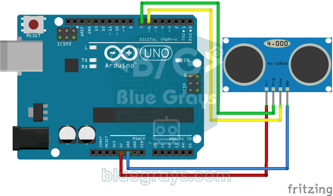
HC-SR04 Distance Measurement (Serial Display)
The HC-SR04 sensor works just like a bat finding its way in the dark: it sends out a sound you cannot hear, listens for the echo and measures how far away the object in front of it is.

LED Blink with ESP32
Teaches basic GPIO output usage with ESP32. We achieve a blinking effect by turning an LED on and off from a digital pin. ESP32 version of the classic blink project on Arduino UNO; the basic blink commands in the Arduino environment are the same, but the ESP32's pin layout and 3.3 V GPIO levels differ from those of the Arduino UNO.

ESP32 Traffic Light
Real traffic light simulation with 3 LEDs red-yellow-green. Timings close to real traffic logic: red long, yellow short, green long. Classic example of sequential GPIO control.
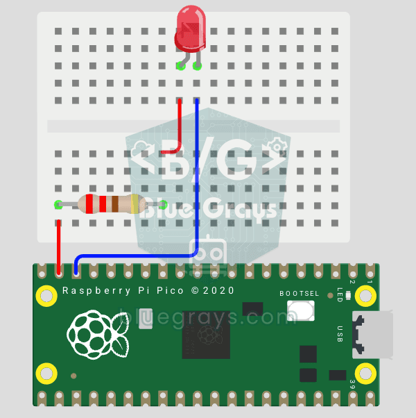
Raspberry Pi Pico: Controlling an External LED (Breadboard)
The next step after the Pico's built-in LED: connect an external LED on a breadboard and control it through pin GP14. You'll learn how to use any of the Pico's GPIO pins as an output, the LED's polarity (long leg = anode/+, short leg = cathode/–) and why a current-limiting resistor (220Ω) is a must. Without the resistor, too much current flows through the LED and it can burn out.
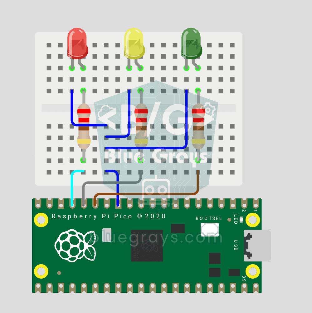
Raspberry Pi Pico Traffic Light Simulator (3 LEDs Sequential)
We recreate real traffic light logic with red, yellow and green LEDs, the first Pico project to move up to 3 LEDs! Green says "go" for 4 seconds, yellow "get ready" for 1.5 seconds, red "stop" for 3 seconds, and red+yellow "set off" for 1 second (the European traffic light pattern). You'll learn to define functions (def all_off()), state machine logic and multi-GPIO synchronization.