
Perfboard Soldering Guide: From Breadboard to Permanent Circuit
Build a permanent circuit on perfboard: perfboard vs stripboard, layout planning, header sockets, jumper wires, wire colours, enclosures and a short test.

Perfboard is the cheapest and fastest way to turn a circuit that runs on your breadboard into a permanent, soldered one. These boards have holes on a 2.54 mm grid with a small copper pad around each hole: you push the parts through, solder their legs and make the connections with wire or solder. The result is a circuit that doesn't fall apart when it vibrates, fits in a box and keeps running for months. It's the only permanent method you can finish the same day without ordering a PCB.
In this guide you'll learn the difference between perfboard and stripboard, how to choose the right board and how to draw a layout plan on paper before you place a single part. Then we'll make the Arduino and sensor modules removable with pin headers, route connections with solder trails, bare wire and jumper wires, pick a wire colour scheme, protect the power rail and fit the circuit into a project box. The last part covers the tests you should run before powering up for the first time, an Arduino sketch that finds shorts by itself and the most common faults with their fixes.
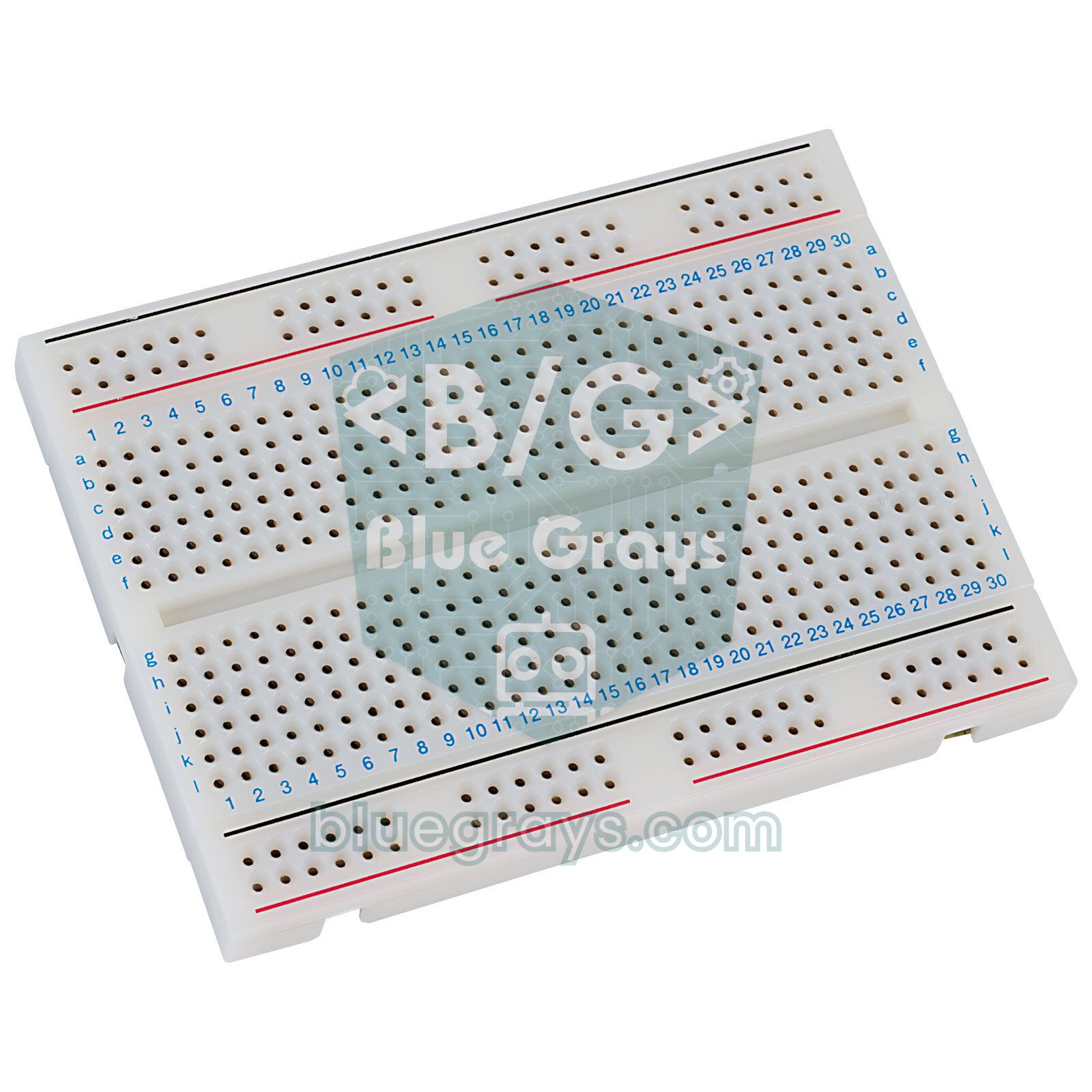
What is perfboard, and how is it different from a breadboard?
The spring contacts inside a breadboard loosen over time, jumper wires pop out at the slightest tug and every contact adds a resistance that wanders between a few milliohms and a few ohms. That's fine on the desk, but in a robot car, a door alarm or an irrigation system the circuit gets shaken and faults like "sometimes it works, sometimes it resets" begin. Perfboard is a prototyping board with a copper pad around every hole and no pre-made connections between them. The cheap brown boards are made of resin-impregnated paper (FR-2, often called phenolic or pertinax), while the green ones are fibreglass (FR-4). The holes are 2.54 mm (0.1 inch) apart, which matches the pitch of Arduino pins, ICs and pin headers.
| Feature | Breadboard | Perfboard | Stripboard | Ordered PCB |
|---|---|---|---|---|
| Permanence | None, contacts loosen | Permanent, soldered | Permanent, soldered | Permanent, the sturdiest |
| Build time | Minutes | 1–3 hours | 1–2 hours | Design + 1–3 weeks shipping |
| Ease of changes | Very easy | Medium | Medium | Hard |
| Cost for one | Reusable | Very low | Very low | Low, but there's a minimum order |
| Best for | Experimenting and learning | A one-off permanent project | ICs and row-based circuits | Many copies and SMD parts |
Perfboard vs stripboard
On perfboard every hole sits alone with its own copper pad; no hole is connected to another. You make all the connections. That gives you complete freedom, but every connection needs its own wire or solder trail. Stripboard (often sold as Veroboard) has copper strips running along each row, so all holes on the same strip are already connected. You decide where a track ends by cutting the strip. Stripboard is especially quick for ICs, but if you forget to cut the strips under the chip, the opposite pins are shorted together. There's also a "protoboard" type printed in a breadboard layout: rows of 5 holes with power rails on both sides, so you can transfer a breadboard layout almost unchanged.
| Type | Material and look | How you connect | Pros | Cons |
|---|---|---|---|---|
| Single-sided perfboard | FR-2, brown, copper on one side | Every link with wire or a solder trail | Cheapest, easy to cut | Pads lift with too much heat |
| Double-sided perfboard (FR-4) | Green fibreglass, plated-through holes | Every link with wire or a solder trail | Sturdy, pads rarely lift, solder on both sides | Slightly pricier, harder to cut |
| Stripboard | FR-2 or FR-4, strips along the rows | Strips are cut to separate tracks | Fast, few wires | An uncut strip causes a short |
| Breadboard-style protoboard | Usually FR-4, rows of 5 | Same as a breadboard | The layout transfers as is | Less flexible, larger |
Tools and materials you'll need
- Soldering iron: temperature-controlled, 40–60 W; 320–350 °C is enough for leaded solder, 350–380 °C for lead-free.
- Solder wire: 0.6–0.8 mm with a flux core. Sn60/Pb40 leaded solder flows more easily; lead-free solder (SAC305) needs a higher temperature.
- Flux: pen or paste; it makes solder trails and desoldering much easier.
- Wire: solid-core 0.5 mm (AWG 24) insulated hook-up wire in several colours, plus bare tinned copper wire for power rails.
- Connectors: 2.54 mm female and male pin headers, 5.08 mm screw terminal blocks and, if needed, JST-XH sockets.
- Cutting and measuring: side cutters, tweezers, a multimeter (the continuity beep is a must), and a 3.5–4 mm drill bit or a craft knife for stripboard.
- Helpers: a desoldering pump or wick, a third hand or board holder, and a magnifier or your phone camera.
Drawing a layout plan: on paper first
The biggest time waster in a permanent build is starting to solder without a plan. Use squared paper where each square is a hole, or treat the cells of a spreadsheet as holes. First finalise your schematic; if reading schematics is hard for you, take a look at the how to read a circuit diagram article. Then place the large, fixed parts: the Arduino Nano, the ESP32 board, the relay module and the connectors that will leave the box. Putting connectors along the edge of the board keeps cables from winding around inside the box. Keep temperature sensors away from parts that get warm, such as the voltage regulator and relays. Leave room right next to the supply pin of each IC for a 100 nF decoupling capacitor.
- List the parts you'll use and the pin count of each; measure how many holes each module covers on the board.
- Line up the connectors and terminal blocks along one edge of the board; put the power input in a corner.
- Mark the position of the two rows of female headers for the Arduino or ESP32; count the holes between the rows according to the width of the board.
- Draw a 5V (or 3.3V) rail along one edge of the board and a GND rail along the other, so every module reaches them by a short path.
- Draw the signal paths; avoid crossings where you can, and when two must cross, take one over the top side with an insulated jumper wire.
- If you're using stripboard, mark every cut with an X; don't forget the strips under the ICs.
- Check every connection in the schematic by ticking it off on the plan with a highlighter; no connection should be left unmarked.
Making modules removable with headers
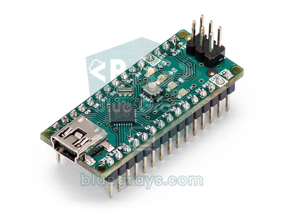
The golden rule of permanent circuits is to use female pin headers instead of soldering the Arduino Nano, the ESP32 board or the sensor modules directly to the board. That way you can plug in a new board if one dies, upload code off the board and reuse the same Nano in another project. An Arduino Nano needs two 15-pin female headers; an ESP32 DevKit needs two 15-pin or two 19-pin headers depending on the board. On the Nano, 5 empty holes remain between the two rows (the rows are 15.24 mm apart, which is 6 hole steps); ESP32 boards come in different widths, so count the holes between the two rows on your own board first. The male pins of sensor modules sit in female sockets in the same way.
| Connector | Use | Current (approx.) | Note |
|---|---|---|---|
| Female pin header 2.54 mm | Socket for Arduino, ESP32 and modules | 1–3 A per pin | Cut to the length you need with side cutters |
| Male pin header 2.54 mm | External links with jumper wires, test points | 1–3 A per pin | A row of 4 is handy for serial and I2C |
| Screw terminal block 5.08 mm | Power input, motor, pump, 12 V lines | 10 A and more, depending on model | Lets you remove cables without desoldering |
| JST-XH 2.5 mm | Battery, sensor cable, a link that can't be reversed | 3 A | Polarised, so it can't be plugged in backwards |
| DC jack 5.5×2.1 mm | Power adapter input | 2–5 A, depending on model | The centre pin is usually positive |
Routing: solder trails, bare wire and jumper wires
There are three ways to connect things on perfboard. A solder trail joins two or three neighbouring pads with plenty of flux and solder; it's quick for short, low-current signals, but long trails get brittle. Bare tinned wire is laid over the pads and soldered every two or three holes; it's the sturdiest option for long rails such as 5V and GND. The legs you clip off resistors and diodes are a perfect source for this. An insulated jumper wire is a short wire run over the top side where two tracks cross. A 0.5 mm wire carries around 1 A comfortably; for loads that draw more current, such as a motor, a pump or an LED strip, use thicker wire or solder two wires side by side.
- Solder the lowest parts first: wire links, resistors and diodes. Bend their legs 30–45 degrees so they don't fall out when you flip the board.
- Next, place the IC sockets and pin headers; solder one pin first, fix the alignment, then carry on.
- After the ceramic capacitors, transistors and LEDs, leave the electrolytic capacitors, terminal blocks and relays until last.
- Finish each joint in 2–3 seconds: touch the iron tip to both the pad and the leg, feed the solder from the opposite side; the result should be a small, shiny cone.
- Clip the legs with side cutters after soldering and collect the offcuts from the bench; one stray leg trapped under the board means a short circuit.
- When each section is done, check the connections you just made with the multimeter's continuity mode; finding a problem early is far easier than hunting for it later.
If you're not confident about your technique, do the exercises in the how to solder guide first. A cold joint looks grey and dull and doesn't fully wrap around the leg; under vibration the connection breaks, and the fault only shows up when the circuit is shaken.
Wire colour scheme
A colour scheme isn't a standard, it's a habit; but if you use the same one in every project, you'll see at a glance what goes where when you open the box months later. The important thing is never to use the power and ground colours for anything else. If there's more than one voltage (for example a 12 V pump, a 5 V Arduino and a 3.3 V sensor), each one should have its own colour.
| Colour | Suggested meaning | Example |
|---|---|---|
| Red | 5V or the main positive supply | Arduino 5V rail |
| Orange | 3.3V | Supply for the ESP32 and 3.3 V sensors |
| Black | GND | All ground connections |
| White or grey | VIN, 9–12 V input | Adapter and battery input |
| Yellow | Digital and analog input signals | Button, sensor output |
| Green | Output signals | LED, relay, MOSFET gate |
| Blue and purple | Communication lines | I2C SDA/SCL, UART TX/RX, SPI |
Keep wires as short as possible, lying flat on the board and bent at right angles; long wires flying in the air pick up noise and get pinched and broken when you close the box. Tie a long bundle down with a cable tie and write a label next to each connector: short notes like "12V", "GND" or "SDA" save a lot of time when you're troubleshooting.
Protecting the power rail
A permanent circuit stays powered for months, so its supply deserves a little extra care. A 1N5819 Schottky diode in series with the input protects the circuit if the adapter is plugged in backwards and drops only 0.3–0.4 V at low currents; a 1N4007 also works but costs about 0.7–1 V. A 100 µF electrolytic at the input and a 100 nF ceramic capacitor next to each IC smooth out the voltage dips that happen when a motor or relay switches on. A 500 mA resettable fuse (polyfuse) cuts the line during a short and recovers by itself once it cools down. If you add a power LED, find the resistor value with the LED resistor calculator. It also matters that the grounds of motors, servos and sensors meet at a single point; we explain why in the common ground article.
Testing and troubleshooting
The moment you finish the board, it's tempting to power it up, but a short circuit can burn out the regulator or the Arduino within minutes. Follow the order below and you'll catch almost every problem before applying power. If you don't know how to use the continuity and resistance modes of your multimeter, see the how to use a multimeter guide.
- Inspect the underside of the board in good light with a magnifier, or take a close-up photo with your phone; look for thin solder bridges between neighbouring pads.
- With the Arduino and modules unplugged, measure the resistance between 5V and GND. If the value stays close to zero there's a short; a value that rises as the capacitors charge is normal.
- On stripboard, confirm there's no continuity between the two neighbouring strips at every point that should be cut.
- Apply power for the first time with the modules and the Arduino unplugged; measure the correct voltage on the 5V and GND pins of the headers.
- Then plug in only the Arduino and upload the short-circuit test sketch below.
- Plug in the modules one at a time and try the circuit each time; if something goes wrong, check the connections of the module you added last.
The sketch below searches for solder bridges between the pins of the Arduino Nano by itself. First it sets every pin as an input with the internal pull-up resistor; a pin that reads LOW despite the pull-up is shorted to GND. Then it drives the pins LOW one by one for 20 microseconds and reads all the others; a pin that reads LOW at that moment is bridged to the driven pin. You'll see the results in the Serial Monitor at 9600 baud.
1// Delikli pertinaks kısa devre testi / perfboard short-circuit test
2// Yalnız Arduino Nano takılıyken, modül soketleri boşken çalıştır
3// Run with only the Arduino Nano plugged in and module sockets empty
4
5// D0-D1 (USB seri), D13 (kart LED'i) ve A6-A7 (yalnız analog) yok
6// D0-D1 (USB serial), D13 (onboard LED) and A6-A7 (analog only) are skipped
7const uint8_t pinler[] = {2, 3, 4, 5, 6, 7, 8, 9, 10, 11, 12, A0, A1, A2, A3, A4, A5};
8const uint8_t PIN_SAYISI = sizeof(pinler) / sizeof(pinler[0]);
9bool gndKisa[PIN_SAYISI];   // GND'ye kısa olan pinler / pins shorted to GND
10
11void pinAdi(uint8_t pin) {
12  if (pin >= A0) {
13    Serial.print('A');
14    Serial.print(pin - A0);
15  } else {
16    Serial.print('D');
17    Serial.print(pin);
18  }
19}
20
21void setup() {
22  Serial.begin(9600);
23  for (uint8_t i = 0; i < PIN_SAYISI; i++) {
24    pinMode(pinler[i], INPUT_PULLUP);   // hepsi yukarı çekili giriş / all inputs with pull-up
25  }
26  delay(10);
27  uint8_t sorun = 0;
28
29  // 1) GND'ye kısa devre: çekme direncine rağmen LOW okunan pin
30  // 1) Short to GND: a pin that reads LOW despite the pull-up
31  for (uint8_t i = 0; i < PIN_SAYISI; i++) {
32    gndKisa[i] = (digitalRead(pinler[i]) == LOW);
33    if (gndKisa[i]) {
34      pinAdi(pinler[i]);
35      Serial.println(F(" -> GND ile kisa devre / shorted to GND"));
36      sorun++;
37    }
38  }
39
40  // 2) Pinler arası köprü: birini çok kısa LOW yap, diğerlerini oku
41  // 2) Bridges between pins: pull one LOW very briefly, read the others
42  for (uint8_t i = 0; i < PIN_SAYISI; i++) {
43    digitalWrite(pinler[i], LOW);       // önce çekme direncini kapat / disable the pull-up first
44    pinMode(pinler[i], OUTPUT);         // sonra LOW sür / then drive LOW
45    delayMicroseconds(20);
46    for (uint8_t j = i + 1; j < PIN_SAYISI; j++) {
47      if (!gndKisa[j] && digitalRead(pinler[j]) == LOW) {
48        pinAdi(pinler[i]);
49        Serial.print(F(" <-> "));
50        pinAdi(pinler[j]);
51        Serial.println(F(" kopru / bridge"));
52        sorun++;
53      }
54    }
55    pinMode(pinler[i], INPUT_PULLUP);   // pini hemen bırak / release the pin at once
56  }
57
58  Serial.print(F("Bitti, sorun sayisi / done, issues: "));
59  Serial.println(sorun);
60}
61
62void loop() {
63}| Part of the code | What it does |
|---|---|
| pinler[] array | The pins to test; D0 and D1 are on the USB serial line, D13 is connected to the onboard LED and A6 and A7 are analog only, so they're not in the list |
| INPUT_PULLUP | Pulls each pin up to 5V through an internal resistor of about 20–50 kΩ; an idle pin reads HIGH |
| 1st loop | Reports pins that read LOW when they should read HIGH as shorts to GND |
| 2nd loop | Drives one pin LOW briefly; any other pin that reads LOW at the same time is bridged to it |
| delayMicroseconds(20) | The pin is driven only for a very short time, so current doesn't flow for long if a pin is shorted to 5V |
| Symptom | Likely cause | Fix |
|---|---|---|
| Nothing works, the regulator gets hot | A short between 5V and GND, an electrolytic fitted backwards | Cut the power, measure 5V–GND resistance, find the bridge |
| Works and stops when shaken | A cold joint or a cracked solder trail | Reflow the suspect joints with flux |
| One module doesn't respond at all | Mirrored layout, header soldered in the wrong order | Compare the pins with the schematic one by one using continuity |
| Two signals affect each other | An uncut strip or a thin solder bridge | Cut the strip completely, clear the bridge with desoldering wick |
| The Arduino resets when the motor starts | A thin supply rail, a missing capacitor, no common ground | Thicken the power rail, add 100 µF, join the grounds at one point |
| A pad lifted off | Too much heat or holding the iron too long | Connect the broken point to a neighbouring pad with a short wire |
Enclosures: project box, terminal blocks and cable entry
Once the board works, putting it into a project box protects it from dust and shorts and gives it a finished look. ABS plastic boxes are easy to drill; drilling 3 mm holes in the corners of the board and raising it 8–10 mm above the floor of the box with M3 standoffs keeps the solder joints underneath from touching the box. If you connect every external cable to terminal blocks, you never have to cut anything to take the circuit out. For boxes used outdoors, fit a cable gland (such as PG7) at the cable entry and add strain relief inside with a cable tie so a pulled cable doesn't stress the solder joint. If the regulator or relay driver gets warm, drill a few ventilation holes.
- Before mounting, check that the board fits inside the box and the lid doesn't press on the wires.
- Line the USB socket up with the edge of the box, or fix a USB extension cable to the box, so you don't have to open it to update the code.
- Mount user-facing parts such as buttons, LEDs and the display on the lid and connect them to the board with JST or headers, so the lid can be removed completely.
- If you use a relay that switches mains voltage, physically separate the 230 V side from the low-voltage side and cover the terminal blocks.
When perfboard, when a PCB?
For a single permanent circuit, a school project or some home automation, perfboard is the most sensible choice. If you'll build three or more of the same circuit, use SMD parts or the circuit is very crowded, an ordered PCB saves time and is more reliable. The good news: the layout plan and schematic you drew for perfboard are also the starting point of a PCB design. For the next step, have a look at the PCB design with EasyEDA guide. For a small permanent circuit running on batteries, the Arduino Pro Mini is one of the easiest boards to fit on perfboard.
The best way to move from breadboard to a permanent circuit is to start with a project you already have working. In the BlueGrays app you'll find projects like a traffic light, temperature and humidity measurement, smart stair lighting and an irrigation station, each with a step-by-step circuit diagram and code; try them on a breadboard first, then move them onto perfboard with the steps in this guide.
Frequently asked questions
What is perfboard?
Perfboard is a prototyping board with holes on a 2.54 mm grid and a copper pad around each hole. You push parts through the holes and solder them, and make connections with wire or solder trails. It's used to make a breadboard circuit permanent.
What is the difference between perfboard and stripboard?
On perfboard every hole is separate and you make all the connections. Stripboard has copper strips along the rows, so holes on the same strip are already connected and tracks are separated by cutting the strip. Stripboard needs fewer wires, but an uncut strip causes a short.
How do you solder on perfboard?
Set the iron to 320–350 °C, touch the tip to the pad and the leg at the same time, feed solder from the opposite side and finish in 2–3 seconds. A good joint is a small, shiny cone. Solder the low parts first and the tall ones last.
How do you connect traces on perfboard?
Over short distances you can join neighbouring pads with flux and solder. For long rails and power lines, lay bare tinned wire or clipped resistor legs over the pads and solder them. Use insulated jumper wires on the top side where tracks cross.
Can you solder an Arduino directly to perfboard?
You can, but it isn't recommended. With female pin headers you can unplug the Arduino, replace it if it fails and reuse it in another project. Two 15-pin female headers are enough for an Arduino Nano.
How do you find a short circuit on perfboard?
First inspect the underside with a magnifier, then use the multimeter's continuity mode between neighbouring pads and between 5V and GND. If you find a short, clear the bridge with desoldering wick. With the Arduino plugged in you can also hunt for bridges between pins with a test sketch.
Projects to build after reading this
See all projects
LED Blink
The very first hello of electronics: switching a single LED on and off. The Arduino turns the LED on and off at short intervals, so the light blinks quickly.

Traffic Light
A tiny copy of the traffic light you see on the road every day. Red stays on for two seconds, yellow flashes for a moment, green stays on for two seconds, then it goes back to red through yellow…
HC-SR04 Distance Measurement (Serial Display)
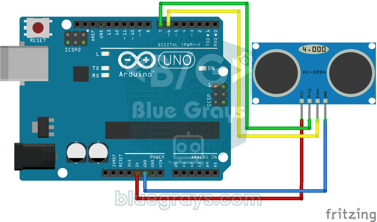
The HC-SR04 sensor works just like a bat finding its way in the dark: it sends out a sound you cannot hear, listens for the echo and measures how far away the object in front of it is.
Temperature and Humidity with DHT11
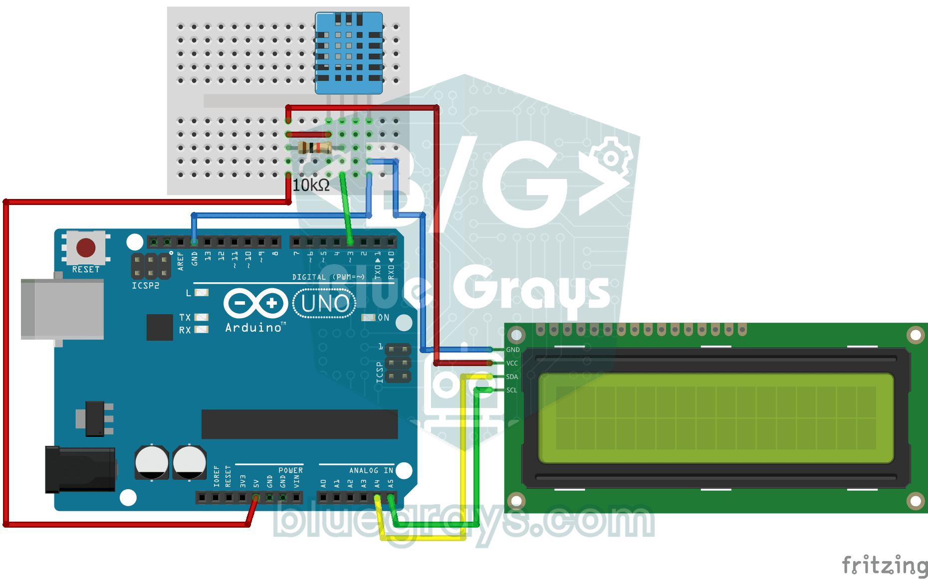
How warm is your room, and is the air humid or dry? The DHT11 sensor measures temperature and humidity, and the Arduino writes the values on a two-line LCD screen, refreshing every couple of seconds.

Smart Stair and Corridor Lighting
Step onto the stairs or into the hallway and the lights come on one step at a time in the direction you are walking.

Smart Irrigation Station
A gardener that waters your plants on its own, so they don't dry out while you're on vacation.

Smart Electronic Safe
A small safe for your valuables that opens with a code. You type your four-digit code on the keypad; if it is right, the servo motor opens the lock, the green light comes on and the screen shows the…