
What Is GND? Why You Need a Common Ground for Servos and Sensors
What is GND and why is a common ground essential? Reference voltage, joining an external supply to Arduino GND, ground loops, star grounding and mains earth.
The short answer to what is GND: it's the 0-volt reference point against which every voltage in the circuit is measured. The name comes from "ground", and you'll also see it called common, chassis or simply the negative side. The Arduino's 5V pin really means "5 volts relative to GND"; a sensor's 2.5 V output only makes sense relative to a GND as well. Most of the mysterious faults beginners run into, such as jittering servos, sensors reading nonsense and boards that reset on their own, actually come from a single missing wire: the common ground.
In this article I'll explain with a simple analogy why GND is a "reference", show how to join grounds correctly when using an external power supply, explain with numbers where ground loops and noise come from, and teach you how to separate motor and sensor grounds with star grounding. We'll also look at how circuit GND differs from the earth in your wall sockets and at the cases where grounds are deliberately kept apart. You'll find the basics of powering boards in Arduino power supply.
What is GND? Why is voltage measured between two points?
Voltage isn't a property of a single point; it's the potential difference between two points. Think of it like height: when you say a table is "80 cm high" you're unconsciously using the floor as the reference. If the same table stands on the 10th floor of a building, its height above sea level is over 30 metres. In electronics, GND is that "floor". When you touch the multimeter's black probe to GND and the red one to a point, you read that point's voltage relative to GND. Put the black probe somewhere else and the same point shows a completely different value. So when we say "5 V" in a circuit we always silently mean "relative to this circuit's GND".
| Term | Meaning | Where you'll see it |
|---|---|---|
| GND / 0V | The circuit's reference point | Arduino, ESP32, Pico and every module |
| Negative (-) | The supply's return terminal, usually tied to GND | Batteries, adapters, bench supplies |
| VCC / VIN / 5V / 3V3 | Positive supply relative to GND | Module and board power pins |
| COM | Common terminal; often GND, but on relays the switch's common contact | Relays, buttons, meters |
| AGND / DGND | Separate analog and digital grounds, joined at one point | ADCs, audio and precision measurement circuits |
| Chassis | Ground connected to a metal case | Cased equipment, vehicles |
| Protective earth (PE) | The green-yellow wire in the socket, for safety | Mains wiring |
Why do you need a common ground?
When the Arduino sends a signal to a servo or module, it's really saying "my pin is at 5 V relative to my GND". The receiver reads that signal relative to its own GND. If the two devices' grounds aren't connected, there's no shared floor between them; in the servo's eyes the Arduino's 5 V could be 5 V, 2 V or -3 V. There's a more basic problem too: current always flows in a closed loop. The signal current leaves the Arduino's pin, passes through the receiver's input and has to return through GND. Without a return path the signal never forms properly, or the wires act like antennas and pick up interference. In short: if two devices send signals to each other, their grounds must be connected.
External power supply and Arduino: joining the grounds
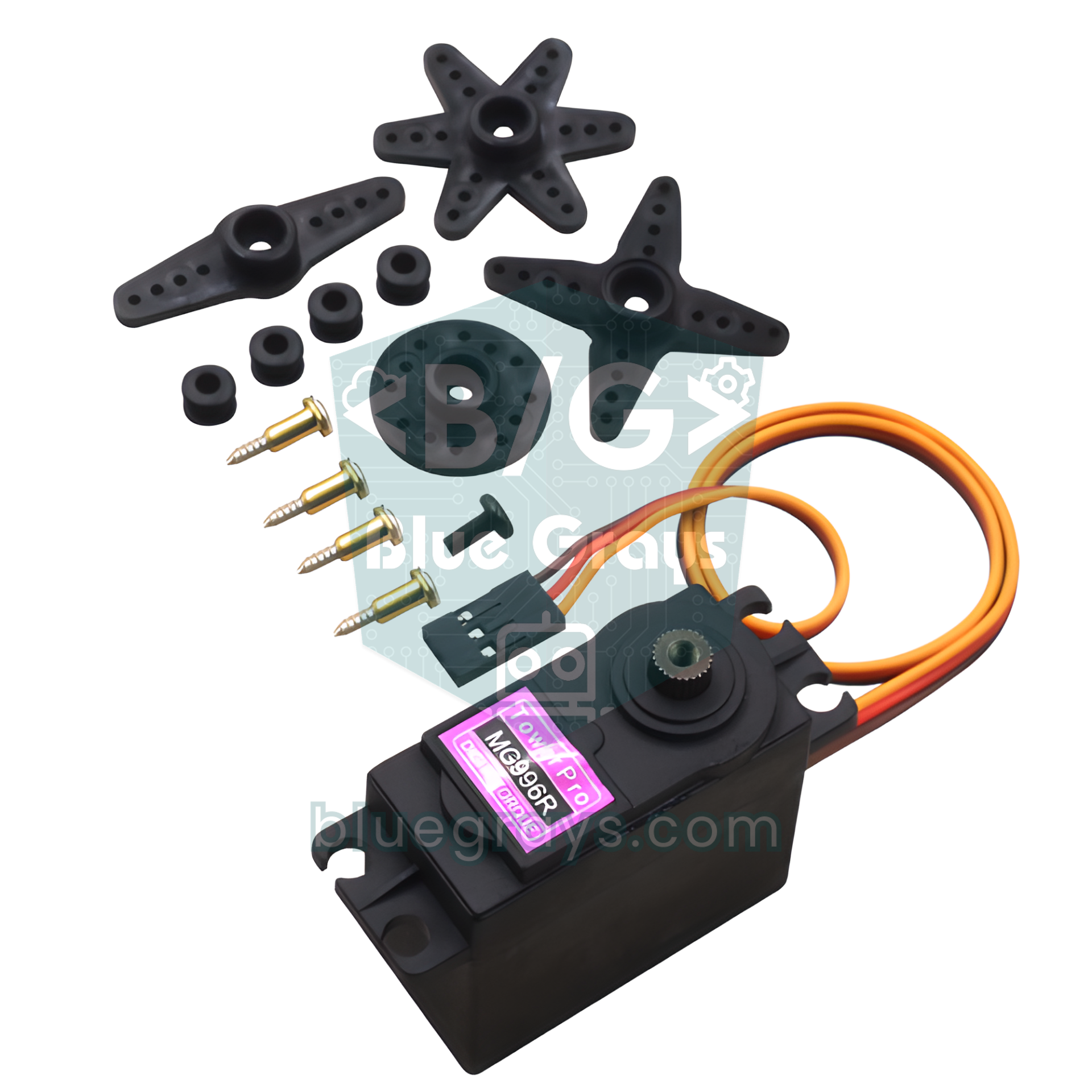
The most common scenario: a servo, motor or LED strip is powered from a separate adapter because it draws more current than the Arduino can supply. In the correct wiring only the grounds are joined and the positive leads stay separate. That way the load current comes from the external supply and returns to it, while the Arduino only provides the signal. The table below shows the wiring of an MG996R servo powered by an external 5 V adapter; the same logic applies to a MOSFET driving a 12 V LED strip or to a motor driver board.
| Wire | Where it goes | Why? |
|---|---|---|
| Servo red (+) | External adapter +5 V | Keeps motor current out of the Arduino |
| Servo brown (-) | External adapter GND | Return path for the motor current |
| Servo orange (signal) | Arduino D9 | PWM position signal |
| Jumper wire | Between adapter GND and Arduino GND | Shared reference for the signal |
| Adapter +5 V to Arduino 5V | Not connected | The two supplies could push current into each other |
1// Harici 5 V ile servo, ortak GND / servo on an external 5 V supply, common GND
2#include <Servo.h>
3
4const int SERVO_PIN = 9;   // turuncu sinyal kablosu / orange signal wire
5Servo servo;
6
7void setup() {
8  servo.attach(SERVO_PIN);
9}
10
11void loop() {
12  for (int a = 0; a <= 180; a += 2) {   // 0 -> 180 derece / degrees
13    servo.write(a);
14    delay(15);
15  }
16  for (int a = 180; a >= 0; a -= 2) {   // 180 -> 0 derece / degrees
17    servo.write(a);
18    delay(15);
19  }
20}Real-world faults: "the servo won't work", "the sensor reads nonsense"
| Symptom | Ground-related cause | Fix |
|---|---|---|
| Servo doesn't turn or jitters | External supply GND not connected to the Arduino | Join the two grounds with a short wire |
| Arduino resets when the motor starts | Motor current returns through the Arduino's GND and the voltage sags | Run the motor GND straight to the supply, use star grounding |
| Analog sensor jumps when the motor runs | Voltage drop from motor current on a shared GND wire | Keep the sensor GND off the motor path |
| Garbage characters on serial | The two boards' grounds aren't connected | Connect GND along with TX and RX |
| LED strip never lights with a MOSFET | The 12 V supply's negative isn't tied to Arduino GND | Join the MOSFET source and both grounds |
| Reading changes when you touch it | Floating input or a loose GND connection | Add a pull-up/pull-down, check the GND wire |
The Arduino resetting when a motor starts is the most confusing fault in this table, because the wiring looks "right". For detailed troubleshooting you can also follow the steps in Arduino keeps resetting; on an ESP32 the same problem usually shows up as a brownout message.
Ground loops and noise: the GND wire is a resistor too
Because schematics draw GND as a single line, we assume it's exactly 0 V everywhere. In reality breadboard strips, jumper wires and solder joints all have some resistance. Ohm's law is merciless here: V = I × R. If the return current of a 2 A motor flows through a GND wire with a total resistance of 0.1 Ω, there's a 0.2 V difference between the two ends of that wire. If an analog sensor shares that wire, the sensor's "0 V" now sits 0.2 V higher. On the Arduino Uno's 10-bit ADC that's an error of about 41 counts (0.2 / 5 × 10²³). If the motor is driven with PWM, the offset swings back and forth hundreds of times a second and you see the readings jump.
A ground loop appears when there's more than one GND path between two devices. For example, if the Arduino is connected to a computer over USB and also to an earthed power supply through a separate wire, ground current can circulate along two different paths, and that closed ring acts like an antenna picking up nearby magnetic fields. The result is the hum you hear in audio circuits or a 50 or 60 Hz ripple in measurements. The fix isn't cutting GND but leaving a single path and keeping large currents from sharing a wire with sensitive signals.
Star grounding: separating motor and sensor grounds
Star grounding means all GND wires meet at one central point instead of being daisy-chained. The motor's large current returns to the supply's negative terminal through its own thick wire, while the grounds of the Arduino, sensors and signal circuits reach the same central point through separate thin wires. That way the voltage drop caused by the motor current stays in the motor wire and doesn't shift the sensors' reference. In practice, follow these steps:
- Choose the supply's negative terminal or a screw terminal as the star point.
- Run the GND of the motor driver (L298N, MOSFET, relay coil) straight to that point with a short, thick wire.
- Connect the Arduino's GND to the same point with a separate wire; don't route it via the motor driver's GND.
- Connect analog sensor grounds to the Arduino's GND pin so the sensor and the ADC share the same reference.
- Add a 100 nF ceramic capacitor across the motor terminals and a 100-470 µF electrolytic at the driver's supply input.
- Route motor and signal wires apart as much as possible and twist each motor's wires together.
Measuring noise: a simple GND test with an Arduino
Instead of guessing how good your grounding is, you can measure it. Build a voltage divider from two 10 kΩ resistors between 5V and GND and connect its midpoint to A0; that point should sit at a steady 2.5 V. The code below takes 200 readings from A0 in a row and prints the difference between the largest and smallest as peak-to-peak noise in millivolts. Measure first with the motor off, then with it running; then rearrange the GND wires as a star and measure again.
1// Basit GND gürültü ölçer / simple ground noise meter
2const int SENSOR_PIN = A0;   // ölçülen sinyal / signal under test
3const int SAMPLES = 200;     // yaklaşık 22 ms'lik örnek / about 22 ms of samples
4const float VREF = 5.0;      // Uno ADC referansı / Uno ADC reference
5
6void setup() {
7  Serial.begin(115200);
8}
9
10void loop() {
11  int minV = 1023, maxV = 0;
12  long sum = 0;
13  for (int i = 0; i < SAMPLES; i++) {
14    int v = analogRead(SENSOR_PIN);
15    if (v < minV) minV = v;
16    if (v > maxV) maxV = v;
17    sum += v;
18  }
19  float avgVolt = sum / (float)SAMPLES * VREF / 1023.0;
20  float ripplemV = (maxV - minV) * VREF / 1023.0 * 1000.0;   // tepe-tepe / peak-to-peak
21
22  Serial.print("ortalama / average: ");
23  Serial.print(avgVolt, 3);
24  Serial.print(" V   tepe-tepe / peak-to-peak: ");
25  Serial.print(ripplemV, 0);
26  Serial.println(" mV");
27  delay(500);
28}
In a well-built circuit, peak-to-peak noise is around 1-2 ADC counts, or 5-10 mV. If it climbs above 50 mV when the motor runs, some wire is sharing the GND path with the motor. 200 mV or more usually points to a loose GND connection, motor current flowing through the breadboard or an external supply that was never joined. This simple test proves within minutes that, in most "the sensor reads nonsense" cases, the problem isn't the sensor but the grounding.
When are grounds deliberately kept separate?
The only exception to "join all the grounds" is isolation. An optocoupler or relay carries the signal with light or a magnetic field and leaves no electrical connection between its two sides. In that case the two sides' grounds are deliberately kept apart: one is the Arduino side, the other the mains or noisy motor side. On relay modules with a JD-VCC jumper, when the jumper is removed and the coil is powered from a separate supply, that supply's GND is not connected to the Arduino; that's the whole point of isolation. For details see What is an optocoupler? and What is a relay module?. Without isolation, any two circuits that exchange signals need a common GND.
Is mains earth the same as circuit GND?
No. The green-yellow wire in your wall sockets is protective earth and really goes to an electrode buried in the ground. Its job is safety: if the live wire touches the case of a metal-cased appliance, current flows down this path and the fuse or residual current device cuts the circuit. The GND in an Arduino circuit is just that circuit's own reference, and in a project powered by a battery or adapter it has no connection to the earth at all. In some adapters and computers the circuit GND may be tied to protective earth, which is one cause of ground loops. In hobby projects, never try to connect circuit GND to the mains neutral or earth wire yourself.
Common GND with 5 V modules on the ESP32 and Pico
The ESP32 and the Raspberry Pi Pico run at 3.3 V; when you connect a 5 V module you put a level shifter in between. The level shifter has GND pins on its low (LV) and high (HV) sides, and both must be connected; it can only translate the two sides' signals relative to a shared reference. The same applies when the ESP32 runs from USB and a 12 V LED strip from a separate adapter: the MOSFET's source, the adapter's negative and the ESP32's GND must meet at one point. You'll find how level shifters work in logic level converter.
GND checklist
- Are the grounds of both devices that exchange signals connected?
- With external supplies, are only the grounds joined and the positives kept separate?
- Do motor, relay and LED-strip currents return to the supply without passing through the Arduino's GND pin?
- Are analog sensors connected to a GND path that doesn't carry motor current?
- Are GND wires thicker than signal wires and as short as possible?
- Where an optocoupler or a JD-VCC relay is used for isolation, are the two sides really separate?
- If in doubt, have you checked the connection between GND points with the multimeter in continuity (beep) mode?
GND is the quietest but most important wire in a circuit: when it's done right nobody notices, and when it's forgotten everything breaks. If you don't know how to test continuity with a multimeter, how to use a multimeter will help. In the BlueGrays app you'll find projects that need an external power supply, such as servo motors, an L298N robot car, an obstacle-avoiding robot, a 230 V lamp with a relay and smart irrigation, each with circuit diagrams and code step by step, so you can trace every GND connection on the diagram.
Frequently asked questions
What is GND and what does it do?
GND (ground) is the 0-volt reference point against which every voltage in a circuit is measured. It also forms the path by which current returns to the supply. When an Arduino pin is said to be at 5V or 3.3V, that value is always relative to GND.
Is GND the same as earth ground?
In electronics, GND is the circuit's own reference and doesn't have to be connected to the actual earth. The green-yellow protective earth in your socket goes to an electrode in the ground for safety. In an Arduino project running on batteries or an adapter, GND has no connection to mains earth.
Should an external power supply's GND be connected to the Arduino?
Yes. If a device powered from an external supply receives signals from the Arduino, the two grounds must be joined. Only the grounds are connected; the positive leads stay separate. Otherwise the signal has no shared reference or return path and the servo jitters or doesn't work at all.
What happens if GND is not connected?
The receiving device can't interpret the voltage correctly; servos move randomly, serial links show garbage characters and sensors give unstable readings. In some cases current returns through unexpected paths and can damage pins.
Is negative (-) the same as GND?
In most single-supply circuits the supply's negative terminal is used as GND, so in practice it's the same point. In split supplies such as ±12 V, however, GND is the midpoint between the two supplies and the negative terminal is at -12 V. That's why it's best to look for the GND symbol on the schematic.
How do you prevent a ground loop?
Leave only one GND path between two devices, keep high-current motor wires away from sensitive sensor grounds and join everything at a single star point. If needed, separate the two sides electrically with optocouplers or isolated modules.
Projects to build after reading this
See all projects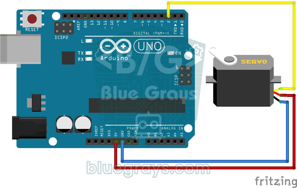
Using a Servo Motor
The arm of a small servo motor turns to three positions in turn: all the way to the start, right to the middle and all the way to the end, waiting two seconds at each stop. The Arduino tells the motor
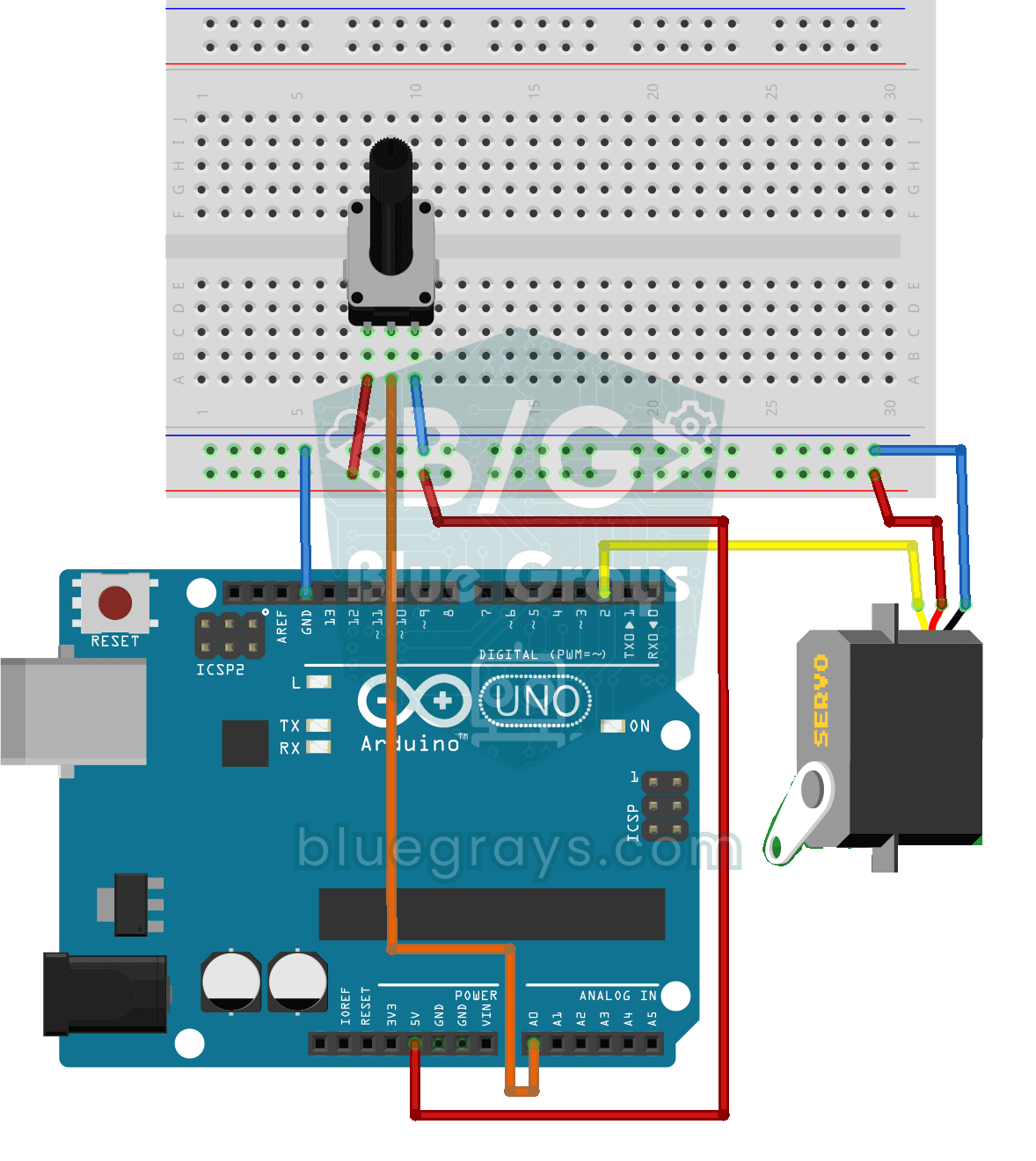
Servo Motor Operation with Potentiometer
As you turn the potentiometer knob, the servo motor's arm turns right along with it: one end of the knob means zero degrees, the other end means half a turn. The Arduino keeps reading the knob's posit

Bluetooth Controlled Car with L298N
Turn your phone into a remote and drive your own robot car. The Arduino receives commands from a remote-control app on your phone through a Bluetooth module and spins the wheels with a motor driver; t

Obstacle Avoidance Robot
How about building a smart vehicle that finds its own way? The Obstacle Avoidance Robot constantly scans its surroundings thanks to the ultrasonic sensor in front of it. When it encounters an obstacle
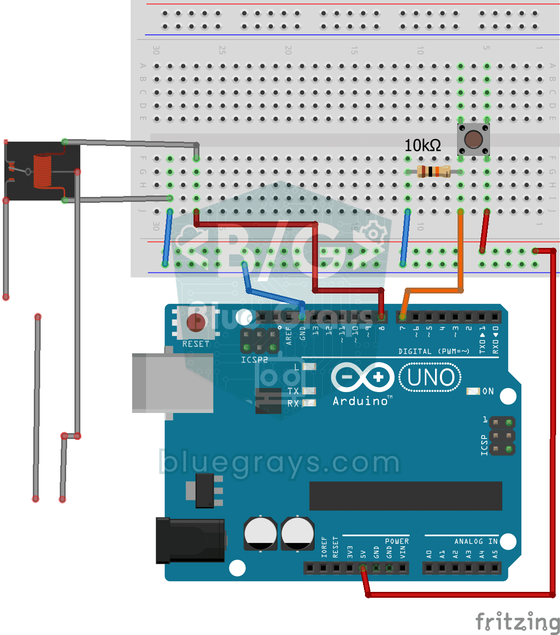
Lighting 220V Bulb with Push Button
As long as you hold the button, a real 220-volt bulb stays lit, and it goes out the moment you let go. The Arduino's tiny signal cannot light the bulb directly, so a relay, an electrically controlled

Smart Irrigation Station
A gardener that waters your plants on its own, so they don't dry out while you're on vacation. A soil moisture sensor measures how wet the soil is; when it gets dry, the Arduino runs the water pump fo

Measuring Light Intensity with an LDR
Want to see how bright your room is as a number? The LDR, a small part that reacts to light, measures the light around it, and the Arduino writes the value to your computer screen every half second. C
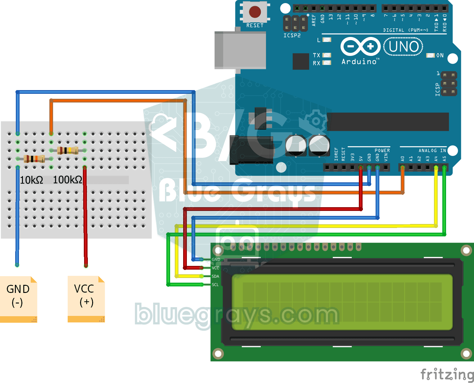
Digital Voltmeter with LCD Display
Find out how much voltage a battery or power adapter gives with a meter you built yourself. A divider made of two resistors brings high voltage down to a level the board can read, and the Arduino calc