
EL-63IntermediatePremiumFlip-flop circuits
4-Bit Shift Register: Shift Bits with the 74HC74
Pick a bit with S1, press S2: the bit enters LED1 and the earlier bits shift one step to the right. The four D flip-flops in two 74HC74s are connected like a chain: each Q goes to the D input of the next. The clock pulse comes from the debounced S2 button via a 74HC14. Four bits entering on a single wire, serial, appear on four LEDs in parallel.
0.0(0)
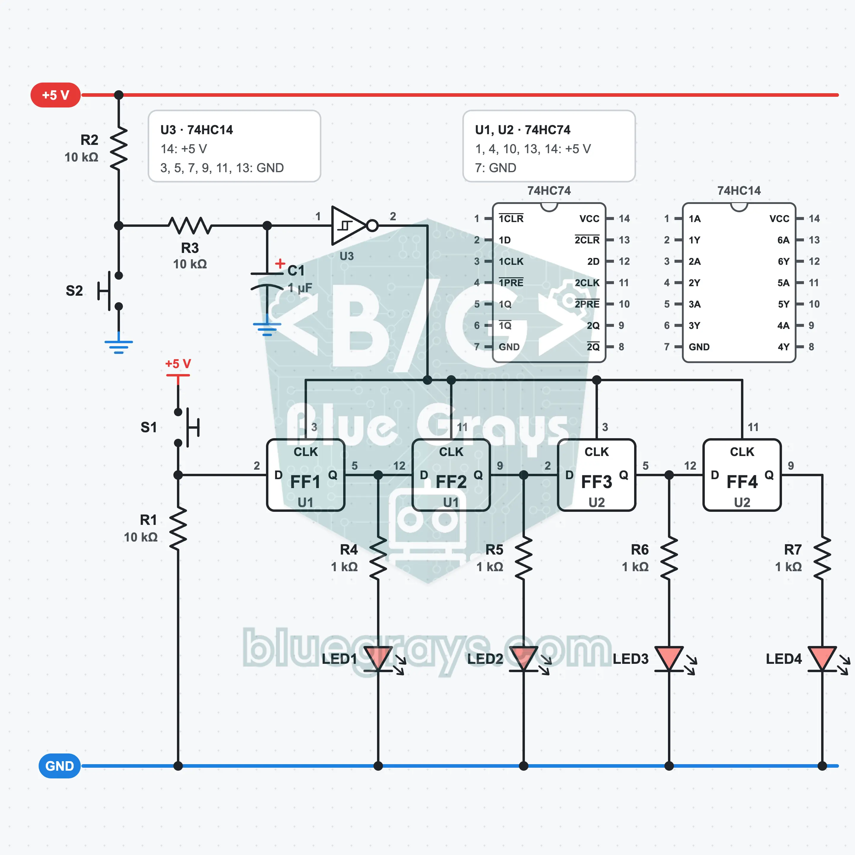
It is built on a full-size breadboard with a 5 V supply, two 74HC74s, one 74HC14, two buttons, seven resistors, one capacitor and four LEDs. S1 is the data input. The clock from S2 is cleaned by R2, R3, C1 and the Schmitt gate of U3, and goes to all four flip-flops together. Q1 is connected to the D input of the second flip-flop, Q2 to the third and Q3 to the fourth. LED1 to LED4 show Q1 to Q4. What you learn: the shift register, serial input and parallel output, the common clock.
Premium Content
This circuit's build steps, how-it-works guide and FAQ are open to Premium members.
- Build Steps
- How It Works
- Frequently Asked Questions