
ESP32 IoT Curriculum: An 8-Week Internet of Things Module
ESP32 IoT curriculum: 8-week plan table, school network and hotspot fixes, Wi-Fi web server code, security and ethics, kit list for 8 groups and final rubric.
When you build an ESP32 IoT curriculum for high school or vocational training, split the module into four layers: first the board senses its surroundings (GPIO and sensors), then it joins a network (Wi-Fi), then it shares data (web server, HTTP client, messages), and finally it learns to run on batteries and stay protected (deep sleep and security). With two lessons a week these four layers fit comfortably into eight weeks: two weeks of hardware, two weeks of network and server, two weeks of data exchange, one week of power and security, and a final project week. By the end, students hand in a device that reads a sensor, shows the reading on a page opened from a phone or sends a message to a phone when something happens, has a calculated battery life and does not keep its password in plain sight inside the code.
This post continues the ESP32 first lesson plan; setup, drivers, the BOOT button and the first LED are covered there and not repeated here. Here you get a week-by-week table of goals, real BlueGrays projects, concepts and outputs, an 80-minute weekly lesson skeleton, why the school network usually keeps the ESP32 out and how to fix it, five questions for your IT department, compilable Wi-Fi web server code, a security and ethics section, a kit list for 8 groups and final project criteria. The examples assume this: you have 24 students working in 8 groups of three, and two lessons a week (2 × 40 minutes). If your class is different, scale the timings.
How the module works: sense, connect, share, save power
An Internet of Things (IoT) class does not teach the internet itself; it teaches how a device talks to the other devices on a network. For that you first need something to measure: a board that joins Wi-Fi but measures nothing has nothing to say on the network. That is why the first two weeks deliberately run without Wi-Fi: students work with a button, an LDR and a temperature and humidity sensor, and settle pin choice and reading intervals. In week three the board joins the network, in week four it becomes a server, in week five it turns into a client that requests data from another server, and in week six it reports an event with a message. Week seven is given to two topics most short IoT workshops skip: battery life and security. Each layer is built on the previous one, so do not change the order; if the Wi-Fi week goes badly, fix the connection problem before moving on.
The 8-week ESP32 IoT lesson plan
Every project in the table is ready in BlueGrays with its circuit diagram, parts list and code. The projects in the first four weeks, including the Wi-Fi connection and web server projects, are completely free; the HTTP client, Telegram, WebSocket and deep sleep projects used from week 5 onwards are Premium. So no student needs Premium in the first month; what to do when Premium is needed is at the end of this post.
| Week | Goal | BlueGrays project | Concept | Output |
|---|---|---|---|---|
| 1 | Read an input and drive an output | ESP32 LED Control with Push Button (Push), ESP32 LED Control with Pushbutton (Toggle) (Free) | GPIO, INPUT_PULLUP, digital input and output, state variable | An LED toggled by a button and the group's pin map |
| 2 | Measure the environment | Reading Light Intensity with the ESP32 LDR Module, ESP32 DHT22 Temperature and Humidity (with LCD Display) (Free) | Analog reading (12 bit, 0–4095), ADC1 and ADC2, I2C, libraries, reading interval | A 10-reading light table in the Serial Monitor, temperature and humidity on the LCD |
| 3 | Connect the board to a network | ESP32 Wi-Fi STA Connection (with LCD Screen) (Free) | Wi-Fi station (STA) mode, SSID, IP address, RSSI (dBm), WiFi.status(), reconnecting | IP, MAC address and signal strength recorded in the network log |
| 4 | Turn the board into a server | ESP32 Asynchronous Web Server (with IP Display on LCD) (Free) and the code in this post | Web server, HTTP request and response, port 80, URL paths (/, /on, /off) | A page that switches an LED from the phone and shows the light value |
| 5 | Turn the board into a client | ESP32 HTTPClient + Weather API (with LCD Screen), Real-Time Clock from the Internet via ESP32 NTP (Premium) | HTTP client, GET request, status codes (200, 404), JSON, time via NTP | Weather or time fetched from the internet; reading the neighbouring group's value |
| 6 | Report an event with a message | ESP32 Motion Alarm System (PIR + Buzzer + LED + Telegram), ESP32 WebSocket Counter (2 Buttons + LCD + Real-Time Web) (Premium) | Notifications, bot token, HTTPS, WebSocket, the publish-subscribe (MQTT) idea | A message on the phone when motion is detected, or a page that updates by itself |
| 7 | Run on batteries and protect the device | ESP32 Deep Sleep — Battery Saving (OLED + RTC RAM Counter) (Premium) | Deep sleep, wake-up sources, RTC memory, average current, keeping passwords in a separate file | A battery life calculation and a project with its password moved to secrets.h |
| 8 | Final project | The group's choice, for example ESP32 DHT22 Temperature and Humidity (with LCD Display) plus the week 4 web page | Combining concepts, documenting, presenting | A working device, a 3-minute presentation, the network log |
Three notes on the table. First, there is no ready-made MQTT project in the app; in week 6 explain MQTT as a concept on the board (devices do not talk to each other directly, they publish messages under a topic to a middleman server, the broker, and whoever is interested subscribes to that topic) and do the hands-on part with the Telegram notification and the WebSocket page. The Telegram details are in the ESP32 Telegram bot post. Second, the Async Web Server project in week 4 needs the AsyncTCP and ESPAsyncWebServer libraries; install them on every computer before the lesson, otherwise compiling stops at the first line. Third, the neighbouring group exercise in week 5 needs no internet: group A's ESP32 reads the /deger address on the server group B built in week 4. If the school has no internet access, this week still works.
The weekly lesson skeleton: 80 minutes
Running every week on the same skeleton means students spend their energy on the new concept, not on getting used to a new routine. If you can schedule the two lessons back to back, the flow below works as one block; if not, it works as two 40-minute halves, and in that case do not take the circuit apart at the end of the first lesson, store it built in the box. The network log is a one-page record each group keeps: date, the board's IP address, MAC address, signal strength, the error they ran into and how they fixed it. From week 3 on, half of all debugging is done by looking at this log.
| Minutes | Stage | What happens? |
|---|---|---|
| 0–10 | Warm-up | Last week's exit question is discussed, groups open their network log, boxes are handed out. |
| 10–20 | Concept | The week's single concept is drawn on the board: for week 4, a phone, an ESP32 and the request and response arrows between them. |
| 20–30 | Reading the code | The week's project is projected, the summary and step-by-step explanation in the Understand the code tab are read together, students predict the output. |
| 30–55 | Build and upload | Groups build the circuit, upload the code and see the first output in the Serial Monitor. Any group stuck for more than 3 minutes gets a spare kit from you. |
| 55–70 | Change one thing | Each group changes a single thing: refresh interval, page text, threshold or sleep time. The change goes into the network log. |
| 70–80 | Wrap-up | The exit question is answered in writing, the circuit is taken apart or stored built in the box, parts are counted. |
School network reality: why the ESP32 won't join the school Wi-Fi
Most IoT modules stall because of the network, not the code. The classic ESP32 only works on the 2.4 GHz band; it never sees an access point that broadcasts on 5 GHz only. School networks often do not use a single shared password like a home network, but enterprise authentication with a username and password (WPA2-Enterprise); the ESP32 can support this with extra code, but it means writing a student's or teacher's personal account password into the code, which is not acceptable in class. Guest networks open an approval page in the browser after connecting (a captive portal); the ESP32 has no screen or browser, so it cannot get past that page: it looks connected but never reaches the internet. Some schools only allow devices whose MAC address has been registered in advance. The last trap is the least known: guest networks usually isolate devices from each other (client isolation). In that case the ESP32 joins the network and even shows its IP address, but the phone on the same network cannot reach that address and the week 4 web server never opens.
| Network type | Does the ESP32 connect? | For the web server week | Note |
|---|---|---|---|
| 2.4 GHz network with a single password (WPA2-PSK) | Yes | Suitable | Same as a home network; rarely open to students at school |
| Network broadcasting on 5 GHz only | No, it never sees it | Not suitable | If it is missing from the network list, check the band first |
| Enterprise network with username and password (WPA2-Enterprise) | Technically possible with extra code | Not recommended | A personal account password ends up in the code |
| Guest network with an approval page (captive portal) | Connects but cannot reach the internet | Usually not suitable | Most also have client isolation turned on |
| A phone's personal hotspot | Yes, if 2.4 GHz is on | Suitable | Limited number of devices at once |
| A separate 2.4 GHz router not connected to the school network | Yes | Best option | If internet is needed, agree the connection with IT |
The fix: a phone hotspot or a separate router
The quickest fix is the personal hotspot on your phone. On an iPhone, turning on Maximize Compatibility in the Personal Hotspot settings switches the broadcast to 2.4 GHz; on Android you choose the 2.4 GHz band in the hotspot settings. This also gives internet access, but phones only accept a limited number of devices at once, and with 8 groups plus student phones the limit fills up quickly. A practical rule: if the 8 ESP32 boards join the teacher's phone, the 8 student phones that will open the browser must not join a second phone, because the phone and the ESP32 have to be on the same network. So in weeks 3 and 4, put 4 groups on one hotspot and the other 4 on a second hotspot, and have each group test with a single phone.
If you will repeat the module every year, the permanent fix is a separate 2.4 GHz router used only for this class. The router works without being connected to the school network; weeks 3 and 4 and the neighbouring group exercise can be done without internet, because the ESP32 and the phone are on the same local network. Internet is only needed in weeks 5 and 6 (weather, NTP, Telegram); for those two weeks, either use a hotspot or plan connecting the router to the school network together with IT. Change the network name and password every term, and change the router's admin password on day one. If there is no physical network at all, the default network name in the code of the app's Wi-Fi projects is Wokwi-GUEST; the same code can be tried with this network in the Wokwi simulator in a browser. Ask your IT department these five questions at least two weeks before the module starts:
- Is there a network at school that broadcasts on 2.4 GHz with a single shared password (WPA2-PSK), and if so, can class devices use it?
- Does the guest network have a captive portal and client isolation? Can two devices on the same network reach each other?
- Do devices need to be registered in advance by MAC address? If so, by when do you need the list of 9 boards?
- Is it within school rules to use a separate router in the lab that is not connected to the school network, or a hotspot from the teacher's phone?
- If the ESP32 boards need internet access in weeks 5 and 6, which connections does the firewall allow (websites, time servers, messaging services)?
The code: an ESP32 that joins Wi-Fi and shows a sensor value on a page
The code below is the core of week 4 and uses only the WiFi.h and WebServer.h libraries that come with the ESP32 board package, so no extra libraries are needed. The circuit stays from week 2: the LDR module's VCC pin to 3V3, GND to GND, AO to GPIO34. GPIO34 is on ADC1, so it can still be read while Wi-Fi is on. Before uploading, replace the two placeholders AG_ADI (network name) and AG_SIFRESI (password) with the details of your own 2.4 GHz network, or move these two lines into a separate file called secrets.h, as you will do in week 7; if the code finds that file, it uses it.
1// ESP32 Wi-Fi + web sunucu: LDR değerini tarayıcıda göster / ESP32 Wi-Fi + web server: show the LDR value in a browser
2#include <WiFi.h>
3#include <WebServer.h>
4
5// Ağ bilgileri: secrets.h varsa oradan gelir / Network credentials: taken from secrets.h if it exists
6#if __has_include("secrets.h")
7#include "secrets.h"
8#else
9const char* WIFI_SSID = "AG_ADI";       // 2,4 GHz ağın adı / Name of the 2.4 GHz network
10const char* WIFI_PASS = "AG_SIFRESI";   // Ağ şifresi / Network password
11#endif
12
13const int LDR_PIN = 34;   // ADC1 pini, Wi-Fi açıkken de okunur / ADC1 pin, still readable while Wi-Fi is on
14
15WebServer server(80);     // 80 numaralı portta web sunucu / Web server on port 80
16
17// Ana sayfa: ölçümü HTML olarak gönder / Home page: send the reading as HTML
18void handleRoot() {
19  int raw = analogRead(LDR_PIN);              // 0-4095 ham değer / Raw value 0-4095
20  int percent = map(raw, 4095, 0, 0, 100);    // Modülde ışık arttıkça değer düşer / On the module the value drops as light rises
21  String html = "<!DOCTYPE html><html><head><meta charset='utf-8'>";
22  html += "<meta name='viewport' content='width=device-width'>";
23  html += "<script>setTimeout(() => location.reload(), 5000);</script>";   // 5 saniyede bir yenile / Reload every 5 s
24  html += "<title>ESP32 Grup 1</title></head><body>";
25  html += "<h1>Isik: %" + String(percent) + "</h1>";
26  html += "<p>Ham deger: " + String(raw) + "</p>";
27  html += "<p>Sinyal: " + String(WiFi.RSSI()) + " dBm</p>";
28  html += "</body></html>";
29  server.send(200, "text/html", html);        // 200 = istek başarılı / 200 = request OK
30}
31
32// Yalnız sayıyı döndüren adres / Address that returns only the number
33void handleValue() {
34  server.send(200, "text/plain", String(analogRead(LDR_PIN)));
35}
36
37void setup() {
38  Serial.begin(115200);
39  analogReadResolution(12);                   // 12 bit: 0-4095
40  WiFi.mode(WIFI_STA);                        // İstasyon modu: var olan ağa katıl / Station mode: join an existing network
41  WiFi.begin(WIFI_SSID, WIFI_PASS);
42  Serial.print("Baglaniliyor / Connecting");
43  unsigned long start = millis();
44  while (WiFi.status() != WL_CONNECTED && millis() - start < 20000) {   // En fazla 20 sn bekle / Wait up to 20 s
45    delay(500);
46    Serial.print(".");
47  }
48  if (WiFi.status() != WL_CONNECTED) {
49    Serial.println("\nBaglanamadi, yeniden basliyor / No connection, restarting");
50    delay(2000);
51    ESP.restart();
52  }
53  Serial.print("\nIP: ");
54  Serial.println(WiFi.localIP());             // Telefonda bu adresi aç / Open this address on the phone
55  server.on("/", handleRoot);                 // Ana sayfa: IP/ / Home page: IP/
56  server.on("/deger", handleValue);           // Yalnız sayı: IP/deger / Number only: IP/deger
57  server.begin();
58}
59
60void loop() {
61  server.handleClient();                      // Gelen istekleri karşıla / Serve incoming requests
62}
After uploading, open the Serial Monitor at 115200 baud. When the dots stop, the IP line appears, for example 192.168.43.57. On a phone connected to the same network as the ESP32, open the browser and type this address: the page shows the light percentage, the raw value and the signal strength, and reloads itself every 5 seconds. Cover the LDR with your hand and the percentage drops. Add /deger to the end of the address and you get only the raw number; in week 5 the neighbouring group's ESP32 will read exactly this address with an HTTP client. If the board cannot connect within 20 seconds it restarts itself, so students do not think it has frozen. If the connection never comes up, see the ESP32 not connecting to WiFi post for what the status codes mean.
Security and ethics: the week you should not skip
In an IoT class, security is not taught as a separate slideshow but as a change students make in their own code. In this module students already carry real secrets in three places: the Wi-Fi password, the bot token from week 6 and the data they measure themselves. Give the second half of week 7 to these five topics and ask for a concrete change in each group's project for each one:
- Do not hard-code passwords: Move the Wi-Fi password and bot token into a separate file called secrets.h and leave that file out when sharing code or taking screenshots. One line of code on the projector means everyone in the room knows the password.
- Change default passwords: Router admin panels, the ESP32's own access point (AP) mode and the passwords in ready-made example code are values everyone knows. Change the class router's password on day one, and ask students not to leave example passwords in their projects.
- Your page is open to everyone on the network: The web server in this post has no login screen; anyone on the same network who knows the address can open the page, and in a project with an /on address can also switch the LED. That is why only harmless outputs such as LEDs, buzzers and displays are controlled over the web in class; relays connected to mains voltage are not used in this module.
- Collecting personal data: Temperature and light are not personal data, but a motion sensor logging when people walk down a corridor, a camera or a microphone can become personal data. If a final project idea records people's movement, voice or image, have the class first answer: "Who sees it, how long is it kept, was permission given?"
- Updates and responsibility: A device connected to the internet is not set up once and forgotten. Show students that at the end of the module the class router is switched off, bot tokens are revoked and boards are reset, and discuss who is responsible for a device during its whole life.
Kit list: per group and for 8 groups
The list is for 24 students in 8 groups of three; 9 kits including one spare are enough. Most parts are bought for the first weeks and reused later; the LCD, for example, appears in four projects from week 2 to week 5. No soldering is needed; modules such as the I2C LCD and the OLED connect with male-to-female jumper wires. If you use a bare LDR instead of an LDR module, add a 10 kΩ resistor per group and build the voltage divider together in week 2.
| Item | Per group | For the class (8 groups + 1 spare) | Week used |
|---|---|---|---|
| ESP32 DevKit (30 pin, ESP32-WROOM-32) | 1 | 9 | 1–8 |
| USB data cable (tested) | 1 | 11 | 1–8 |
| Breadboard (830 holes) | 2 | 18 | 1–8 |
| Push button | 2 | 18 | 1, 6 |
| 5 mm LED and 220 Ω resistor | 3 + 3 | 30 + 30 | 1, 3, 4 |
| LDR module (with AO output) | 1 | 9 | 2, 4, 5 |
| DHT22 temperature and humidity sensor | 1 | 9 | 2, 8 |
| 16x2 I2C LCD display | 1 | 9 | 2–5 |
| 0.96 inch SSD1306 OLED display (I2C) | 1 | 9 | 7 |
| PIR motion sensor (HC-SR501) and buzzer | 1 + 1 | 9 + 9 | 6 |
| Jumper wires (male-to-male and male-to-female) | 20 + 10 | about 180 + 90 | 1–8 |
| 2.4 GHz access point (phone hotspot or separate router) | - | 2 hotspots or 1 router | 3–8 |
| Phone or tablet with BlueGrays | 1 | 8 | 1–8 |
Assessment: final project criteria
Keep the final project rule simple: one sensor, one Wi-Fi connection and one way of sharing (a web page or a message). Groups write their idea in one sentence at the end of week 6, list their parts in week 7, build in the first lesson of week 8 and give three-minute presentations in the second. Score with the six criteria below; each is worth 1–3 points, 18 in total. For the general logic of the rubric, the submission form and the portfolio, you can reuse the template from the Arduino class assessment rubric post as it is.
| Criterion | 1: Beginning | 2: Developing | 3: Ready |
|---|---|---|---|
| Sensor and circuit | Circuit built but no value or a meaningless one | Value is read, pin choice cannot be justified | Value read correctly, ADC1 or digital pin choice explained |
| Wi-Fi connection | Connects only with the teacher's help | Connects, but the device stops when the connection drops | Connects, reconnects after a drop, IP and signal strength recorded |
| Data sharing | Data only in the Serial Monitor | Page or message exists but has to be refreshed or triggered by hand | Page refreshes itself or the message goes out on the event automatically |
| Power awareness | Nobody knows how much current the device draws | Battery life calculated but sleep not considered | Calculated with sleep and wake-up interval, result interpreted |
| Security and ethics | Password in plain sight in the code | Password in secrets.h, data not discussed | Password in a separate file, collected data and who sees it written down |
| Documentation and presentation | Network log incomplete, presentation is just a demo | Network log exists, errors met are not explained | Network log complete, one error and its fix explained in the presentation |
Weekly exit questions and a pre-module checklist
- Week 1: On a pin set to INPUT_PULLUP, what does digitalRead() return while the button is pressed, and why?
- Week 2: Why can't a potentiometer on GPIO4 be read while Wi-Fi is on? Which pins should we choose?
- Week 3: If WiFi.status() says not connected, what are the first two things you check?
- Week 4: Why might the IP address you typed into the browser be different next week?
- Week 5: Was your ESP32 a server or a client this week? What do status codes 200 and 404 tell you?
- Week 6: What happens if the bot token shows up in a screenshot? What is the broker's job in MQTT?
- Week 7: On the same battery an ESP32 can run for days when always on and for months in deep sleep. What makes the difference?
- Week 8: What data does your device collect, who can see it and how long is it kept?
- Two weeks before the module: Ask IT the five questions and decide between hotspot and router based on the answers.
- Two weeks before the module: Count the boards and write each board's MAC address on its label (give the list to IT if registration is needed).
- One week before the module: Install the ESP32 board package and the DHT, LiquidCrystal I2C, AsyncTCP and ESPAsyncWebServer libraries on every computer; test with one board.
- One week before the module: Set the hotspot to 2.4 GHz, change its name and password, connect an ESP32 and open its page from a phone.
- One week before the module: Copy a network log page for each group, test the sensors and LCDs and pack them into the boxes.
- Before week 5: Prepare the codes for the Premium projects and tell students which of their details are shared.
Where BlueGrays fits in the module
- ESP32 projects: In Discover › Projects, use Filter to choose the ESP32 platform; there are about 50 ESP32 projects, from Wi-Fi connection to deep sleep. Each has a circuit diagram, a parts list with quantities and copyable source code. Copy Link is handy for opening the code on a computer.
- Understand the code: Minutes 20–30 of every week are spent in this tab: the What does this code do? summary, the Step by step explanation, If you get stuck and the Try it yourself task. It is free on the first four weeks' projects and opens with Premium on Premium projects.
- Pinout tool: In the Pinout tool, selecting any ESP32 pin shows its type and warnings; for an ADC2 pin it says analog reads are not possible while Wi-Fi is on, for an ADC1 pin it says the pin can still be read with Wi-Fi on. Ideal on the projector while choosing pins in week 2. Pinout is a Premium tool.
- Battery life tool: In the Battery life tool you pick the ready-made ESP32 · deep sleep profile; enter battery capacity, awake current and time, sleep current and cycle, and it calculates the estimated run time and average current. Week 7's "always on versus sleeping" comparison is done on this screen. The tool is Premium; free users can see a sample calculation.
- Educator Packages: From week 5 Premium projects are needed, so one account per group should have Premium. A 10-code yearly package covers 8 groups and the teacher; it is a one-time payment, it does not renew, students do not add a card, you see who used each code in My Codes and you can transfer codes to next term's group. A 30-day monthly code handed out in the first lesson of week 5 only just covers the last four weeks; a holiday in between and it falls short. Details are in the Premium codes for your class post.
After eight weeks, students do not just have a working device; they have a habit of thinking about how a device talks on a network, why it fails to connect, how much energy it uses and whose data it collects, and that is exactly what vocational training is looking for. If you want to go through each week's projects, diagrams and Understand the code explanations before class, just open the ESP32 filter in the BlueGrays app.
Frequently asked questions
How many weeks should an ESP32 IoT course take?
With two lessons a week, 8 weeks is enough for the core IoT concepts, from sensors and Wi-Fi to web servers, notifications and deep sleep. If you only have one lesson a week, stretch the same plan to 12–14 weeks or merge weeks 5 and 6. Give the final project at least one full lesson.
Can you teach ESP32 IoT without school Wi-Fi?
Yes. As long as the ESP32 and the phone are on the same local network, the web server and requests between devices need no internet; a 2.4 GHz hotspot on the teacher's phone or a separate router not connected to the school network is enough. Internet is only needed for outside services such as weather, time and Telegram.
Why won't my ESP32 connect to the school Wi-Fi?
The classic ESP32 only works on 2.4 GHz, so a network broadcasting only on 5 GHz never shows up. School networks often use enterprise authentication with a username and password or a captive portal in the browser, and some only allow registered MAC addresses. In these cases a hotspot or a separate router is the most practical option.
Why can't I open the ESP32 web server from my phone?
The most common reason is that the phone is not on the same network as the ESP32: it may be on mobile data or another Wi-Fi network. The second reason is client isolation on guest networks, where devices on the same network cannot reach each other. Try the IP address from the Serial Monitor again with the phone and the ESP32 on the same hotspot.
Do I need to teach MQTT in an IoT class?
It is not essential, but it should be explained as a concept, because most real IoT systems use this model where devices exchange messages by topic through a broker. In an 8-week module it is enough to settle the client-server relationship with HTTP first and introduce MQTT in week six as the publish-subscribe idea.
Are the ESP32 projects in BlueGrays free?
Some of them. The projects used in the first four weeks of this plan, such as button, LDR, DHT22, Wi-Fi connection and Async Web Server, are completely free. The HTTP client, Telegram, WebSocket and deep sleep projects are Premium; for a class you can get bulk codes from Educator Packages on the Profile screen.
Projects to build after reading this
See all projects
ESP32 Wi-Fi STA Connection (with LCD Screen)
In this project, we connect the ESP32 to the home Wi-Fi network in Station (STA) mode in a secure, fault-tolerant manner. We store the SSID and password in a separate secrets.h file to prevent leaking to Git, set up an auto-reconnect mechanism, and display the RSSI signal level and IP address on an I2C LCD screen. The internal LED works as a status indicator. It is a production-grade connection manager.

ESP32 Asynchronous Web Server (with IP Display on LCD)
In this project, we’re turning the ESP32 into an asynchronous web server that you can control from your phone or computer on the same Wi-Fi network. Thanks to the ESPAsyncWebServer library, the server can process multiple requests simultaneously (unlike the classic WebServer.h, which blocks on a single request). You’ll be able to open the ESP32’s IP address in a browser and click the ON/OFF buttons (the /on and /off routes) to turn the LED connected to GPIO 5 on and off.

ESP32 LED Control with Push Button (Push)
The LED lights up when the button is pressed and turns off when released. Shows how the ESP32's digital input pin and internal pull-up resistor are used. The INPUT_PULLUP mode eliminates the need for an external resistor.

Reading Light Intensity with the ESP32 LDR Module
Real-time monitoring of the LDR module's raw ADC value and relative light percentage calculated from dark and light reference values in the Serial Monitor. This percentage is not a lux measurement. Teaches the module’s calibration logic. It is ideal to complete this before Project 10, as it is used to determine the threshold value.

ESP32 DHT22 Temperature and Humidity (with LCD Display)
This project measures ambient temperature and humidity using a DHT22 sensor and displays the data in real time on a 16x2 I2C LCD. Data is read from the sensor using the one-wire protocol via the Adafruit DHT library. This project serves as the foundation for IoT weather stations, smart home automation, or environmental monitoring systems in greenhouses. Communication with the DHT22 is established via the ESP32's GPIO 4 pin.

ESP32 HTTPClient + Weather API (with LCD Screen)
In this project, we use the ESP32 to make a REST API call to a weather API (wttr.in) over the internet using HTTPClient.h. We parse the returned JSON response using ArduinoJson v7 and display the city, temperature, humidity, weather, and wind information on an I2C LCD screen in both Turkish and English. wttr.in is free and does not require an API key—you can simply enter any city name to retrieve that city’s current weather conditions. It automatically updates every 30 minutes, provides differ
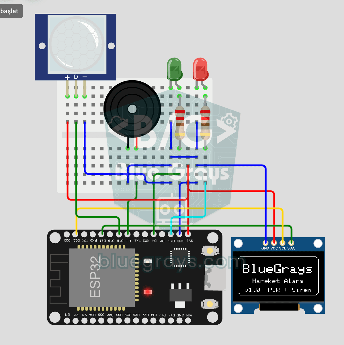
ESP32 Motion Alarm System (PIR + Buzzer + LED + Telegram)
A smart security alarm system that activates the buzzer and LED when the PIR sensor detects motion, while simultaneously sending an instant notification to the owner via Telegram. It includes a 30-second cooldown to limit the frequency of repeated alarms; this mechanism does not validate PIR detections or eliminate false triggers. Suitable for home security, garage monitoring, warehouses, or workrooms. With ESP32-CAM, photo notifications can be added; with the classic ESP32 DevKit V1, text notif

ESP32 Deep Sleep — Battery Saving (OLED + RTC RAM Counter)
The ESP32's Deep Sleep mode reduces current consumption to ~10 µA by shutting down the CPU and most peripherals, making it critical for battery-powered IoT devices. In this project, we use three different wake-up sources: a timer (15 seconds), an external pin (EXT0 — button GPIO 33), and touch (T0/GPIO 4). Variables marked with RTC_DATA_ATTR are preserved during deep sleep—the boot counter, timer wake counter, and button wake counter are continuously tracked. On each wake-up, the SSD1306 OLED