
ESP32 Lesson Plan: First Class Prep Checklist and 40-Minute Flow
ESP32 lesson plan: in the first class every group uploads code and lights an LED. Prep checklist, materials for 24, a 40-minute flow, code and 8 quick fixes.
When you write an ESP32 lesson plan, boil the first class down to one goal: by the end, every group has uploaded code to its own ESP32 and lit an LED. Wi-Fi, sensors and phone control belong to later lessons. Whether 40 minutes is enough depends less on what you do in class than on what you do before it: is the USB-to-serial driver installed, is the ESP32 board package in the Arduino IDE, and does the cable on the desk actually carry data? If those three are ready, the first upload takes five minutes; if not, half the lesson goes on "I can't see the port".
This post gives you a package you can take to class tomorrow: a copyable checklist for one week before, the day before and the morning of the lesson, a materials table, a minute-by-minute 40-minute flow, two sketches that compile, five ways the ESP32 differs from the Arduino Uno, one-minute fixes for the eight most common problems and exit questions. Let's say you have a class of 24 and split the students into 8 groups of three; every number below assumes that. If your periods are 45 or 50 minutes, the extra time is your buffer. If the ESP32 is still new to you, read what is the ESP32 first.
First lesson goal: why just one LED?
In a first ESP32 lesson you have two options: demo an impressive Wi-Fi project, or have everyone get something small working with their own hands. The second teaches far more. To light an LED a student has to run through the whole chain once from start to finish: open the code, pick the board and port, compile, upload, build the circuit, see the result, then change a value and upload again. Once that chain works, later lessons only add new parts. If you jump to Wi-Fi before it works, network passwords, drivers and cables pile on top of each other and telling which one caused the error becomes almost impossible. That's why this plan has no network in the first class: first the board's built-in LED, then a single external LED on the breadboard, and for fast groups both blinking in turn.
Pre-lesson preparation checklist
Split the preparation into three stages. You can copy and print the list or share it with the school's IT technician; jobs that need admin rights, such as installing drivers and software, go through them in most schools. One week before:
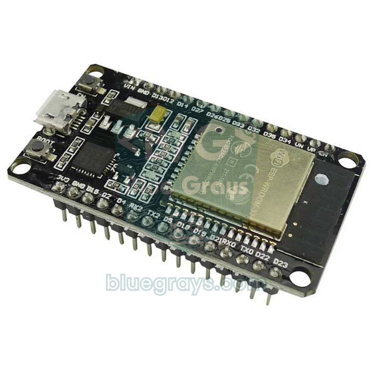
- Count the boards and check the model. This plan is written for the 30-pin ESP32 DevKit (with the ESP32-WROOM-32 module); on 38-pin boards the code is the same, only the pin order differs.
- Read the small chip next to the board's USB port: is it a CP2102, a CH340 or a CH9102? That decides which driver you need.
- Have Arduino IDE 2 installed on the classroom computers. School machines usually need admin rights for installs, so book a slot with IT.
- In the Arduino IDE, install the esp32 by Espressif Systems package from the Boards Manager. It downloads hundreds of megabytes; on a school network, 40 minutes may not be enough if you try it in class.
- Install the USB-to-serial driver, plug in a board and check that a new port appears under Tools > Port.
- Test your cables: upload to a board with each one, sort out the charge-only cables and mark the data cables with coloured tape.
- Plug an ESP32 into a breadboard and check whether free holes remain on both sides. If not, each group gets two breadboards.
- Find out the school network's limits: the ESP32 only connects to 2.4 GHz Wi-Fi, and enterprise networks that ask for a username and password are hard to deal with. You won't use Wi-Fi in the first class, but you'll need this information for later lessons.
The day before, every computer should be ready for class; the aim is that no setup step is done for the first time during the lesson. Set aside ten minutes on the morning of the lesson too. Both lists are in one place:
- Day before: Do a test upload on every computer. Plug in the board, select ESP32 Dev Module and the port, upload the built-in LED sketch and watch the LED blink. The first compile can take more than a minute; this trial also speeds up later compiles.
- Day before: On Windows, put a label with the port number (COM3, COM5 and so on) on the side of the computer. The same board plugged into the same USB socket usually gets the same number.
- Day before: Pack the group boxes: board, cable, breadboard, two LEDs, two 220 Ω resistors, four jumper wires. Keep the spare set on the teacher's desk.
- Day before: Save both sketches to the desktop of every computer; if the internet slows down, students open the code from there.
- Day before: Check that the ESP32 Built-in LED Blink project opens in BlueGrays on the projector.
- Morning of: Turn on the computers, open the Arduino IDE and check that the board is still set to ESP32 Dev Module.
- Morning of: Draw a simple sketch of the board on the whiteboard: USB port, BOOT, EN, GND, 3V3 and GPIO5 (labelled D5 on the board).
- Morning of: Write one line in the corner of the board: "Stuck on Connecting...? Hold BOOT."
- Morning of: Count the LEDs and resistors in the boxes one last time and put the cables on top.
Driver, board package and BOOT: details you need to know
You may see two ESP32 packages in the Arduino IDE Boards Manager. For classroom boards the right one is Espressif's esp32 package; the one called "Arduino ESP32 Boards" is for Arduino's own Nano ESP32. After installing, choose ESP32 Dev Module under Tools > Board > esp32. If the package doesn't show up in the list, you need to add Espressif's package address to the additional boards manager URLs in Preferences; you'll find the steps in what is the ESP32. ESP32 sketches take longer to compile than Uno sketches; even for an LED blink the first compile can take over a minute. Tell students this up front, or they'll keep hitting Upload while the progress bar seems stuck. The board's USB-to-serial chip decides which driver to install:
| USB-to-serial chip | How to spot it on the board | Port name on Windows | Note |
|---|---|---|---|
| CP2102 / CP2104 | Small square chip next to the USB port, marked CP2102 or SiLabs | Silicon Labs CP210x USB to UART Bridge (COMx) | Windows often installs the driver itself; if not, you need Silicon Labs' CP210x driver |
| CH340 (CH340C, CH340G) | Rectangular chip marked CH340 | USB-SERIAL CH340 (COMx) | Needs WCH's CH340 driver; Windows Update sometimes installs it automatically |
| CH9102 | Small square chip on newer boards, marked CH9102 | USB-Enhanced-SERIAL CH9102 (COMx) | Needs WCH's CH9102/CH343 driver; the CH340 driver doesn't recognise this chip |
The BOOT button is wired to the ESP32's GPIO0 pin. When an upload starts, the board has to enter programming mode; most DevKits do this on their own using two signals from the USB-to-serial chip. With some board and cable combinations this automatic switch fails: the "Connecting..." dots in the output keep going and you end up with a "Failed to connect to ESP32" error. The fix is to hold BOOT as soon as "Connecting..." appears and release it when the progress lines starting with "Writing at" begin to scroll. The EN button restarts the board; if the upload finished but the code doesn't seem to run, one press of EN is enough. If the problem keeps coming back on the same board, lowering Upload Speed in the Tools menu from 921600 to 115200 usually helps. On macOS the port name usually starts with cu.usbserial or cu.SLAB_USBtoUART.
Materials list: per group and for a class of 24
Split 24 students into groups of three and you get 8 groups; with one spare you prepare 9 sets. If you prefer pairs, you need 12 groups plus a spare, so 13 sets, and more computers to match. No part needs soldering. The reason for two LEDs and two resistors per group is simple: an LED plugged in backwards or with a broken leg is very common in a first lesson, and you don't want a group waiting.
| Item | Per group | For the class (8 groups + 1 spare) | Note |
|---|---|---|---|
| ESP32 DevKit (30-pin, ESP32-WROOM-32) | 1 | 9 | Use one model only; mixed models mix up the pin order |
| USB data cable (Micro-USB or USB-C, depending on the board) | 1 | 11 | 2 spare cables; all tested and marked |
| Breadboard (830 holes) | 1 | 9 | 2 per group if the board doesn't fit (18 for the class) |
| 5 mm red LED | 2 | 20 | A red LED lights up comfortably at 3.3 V |
| 220 Ω resistor | 2 | 20 | Colour bands: red-red-brown |
| Male-to-male jumper wire | 4 | about 40 | Always use black for GND |
| Computer with Arduino IDE and the ESP32 package | 1 | 8 + the teacher's computer | Labelled with the port number |
| Phone or tablet with BlueGrays open | 1 (optional) | 8 | For reading the diagram and code; a projector also works |
| Parts box or bag | 1 | 9 | Count everything back in at the end |
The 40-minute lesson flow
The flow is built on two free BlueGrays projects: first ESP32 Built-in LED Blink (no circuit, just the board and cable), then LED Blink with ESP32 (GPIO5, a 220 Ω resistor and an LED). Both projects have the parts list, circuit diagram, code, blocks and Understand the code open for free. Hand out three roles in each group and rotate them at every stage: one on the keyboard, one building the circuit, one reading the diagram and code from a phone or the projector. That way nobody spends 40 minutes just watching.
| Minute | Stage | Teacher | Students |
|---|---|---|---|
| 0–4 | Intro and goal | Holds up the board and states the single goal: "Before the bell, every group uploads its own code and lights an LED." Mentions that the board has Wi-Fi like their phones, but it won't be used today. | Share out roles, open the box, count the parts. |
| 4–9 | Getting to know the board | Uses the whiteboard sketch to show the USB port, BOOT and EN buttons and the GND, 3V3 and GPIO5 pins; gives the 3.3 V warning. | Find these points on their own board and spot the built-in LED. |
| 9–17 | First upload: built-in LED | Opens the ESP32 Built-in LED Blink project on the projector, shows board and port selection once, repeats the BOOT note. | Open or copy the code, select ESP32 Dev Module and the port, upload; the LED blinks once a second. |
| 17–21 | Change one value | Asks: "What happens if you write 200 instead of 1000?" and wants a prediction first. | Give their prediction, change both delay() values, upload again and compare the result with the prediction. |
| 21–31 | External LED circuit | Projects the circuit diagram of LED Blink with ESP32, points out the LED's long leg and the resistor's position, walks around and checks each circuit while USB is unplugged. | Unplug USB, build GPIO5 → 220 Ω → LED long leg, short leg → GND, then upload after the teacher's OK. |
| 31–35 | Mini task | Gives fast groups an extra task: make the built-in and external LEDs blink in turn. With stuck groups, checks the cable and LED direction first. | Set both pins as outputs, switch one off while the other is on; groups that finish move on to the Try it yourself task in Understand the code. |
| 35–38 | Pack up | Asks everyone to unplug USB and count the parts. | Take the circuit apart and count the parts back into the box. |
| 38–40 | Exit questions | Writes the four questions on the board or asks them aloud. | Write short answers on paper and hand them in on the way out. |
The code: built-in LED and external LED
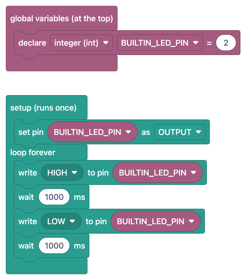
The two sketches below use the same pins and timings as the projects in the app and compile straight away with ESP32 Dev Module selected in the Arduino IDE. The first one blinks the LED on the board once a second. On most ESP32 DevKit boards this blue LED is wired to GPIO2. On the Arduino Uno the built-in LED was on pin 13; students who have used an Uno may type 13 out of habit, so point out the difference early.
1// ESP32 Dahili LED Yakma / ESP32 built-in LED blink
2// Çoğu ESP32 DevKit kartında dahili LED GPIO2'dedir / On most ESP32 DevKit boards the built-in LED is on GPIO2
3int BUILTIN_LED_PIN = 2;   // Kartına göre değişebilir / May differ on your board
4
5void setup() {
6  pinMode(BUILTIN_LED_PIN, OUTPUT);   // Pini çıkış yap / Set the pin as output
7}
8
9void loop() {
10  digitalWrite(BUILTIN_LED_PIN, HIGH);   // LED'i yak / Turn the LED on
11  delay(1000);                           // 1 saniye bekle / Wait 1 second
12  digitalWrite(BUILTIN_LED_PIN, LOW);    // LED'i söndür / Turn the LED off
13  delay(1000);                           // 1 saniye bekle / Wait 1 second
14}
15
The circuit for the second sketch: from GPIO5 to one end of the 220 Ω resistor, from the other end of the resistor to the LED's long leg (anode), and from the LED's short leg (cathode) to GND. The ESP32 pin outputs 3.3 V; about 2 V drops across a red LED, and the remaining 1.3 V across 220 Ω gives roughly 6 mA. That's enough for a clearly visible LED and doesn't strain the pin. If you use a different colour, check the resistor with the LED resistor calculator. In the mini task, fast groups combine the two sketches: they set both pins as outputs in setup() and write one HIGH while the other is LOW in loop().
1// ESP32 ile LED Yakma: harici LED / ESP32 external LED blink
2// Bağlantı: GPIO5 -> 220 Ω direnç -> LED uzun bacak (+), kısa bacak (-) -> GND
3// Wiring: GPIO5 -> 220 ohm resistor -> LED long leg (+), short leg (-) -> GND
4const int LED_PIN = 5;   // Harici LED pini (kartta D5) / External LED pin (D5 on the board)
5
6void setup() {
7  pinMode(LED_PIN, OUTPUT);   // Pini çıkış yap / Set the pin as output
8}
9
10void loop() {
11  digitalWrite(LED_PIN, HIGH);   // Pin 3,3 V verir, LED yanar / Pin outputs 3.3 V, LED on
12  delay(500);                    // Yarım saniye bekle / Wait half a second
13  digitalWrite(LED_PIN, LOW);    // Pin 0 V verir, LED söner / Pin outputs 0 V, LED off
14  delay(500);                    // Yarım saniye bekle / Wait half a second
15}
165 ways the ESP32 differs from the Arduino Uno
Some of your students may have used an Arduino Uno before. The code is written in the same Arduino language and setup() and loop() are where they always are, but the hardware is different, and most errors in a first lesson come from these differences. You can cover the five points below in a few minutes while getting to know the board. For a more detailed comparison, see Arduino vs ESP32.
| Topic | Arduino Uno | ESP32 DevKit | What it means in class |
|---|---|---|---|
| Logic voltage | 5 V | 3.3 V; the pins are not 5 V tolerant | Never put 5 V on a GPIO; check a 5 V module's output voltage before connecting it |
| Pin numbers | D0–D13 and A0–A5 | GPIO numbers are used; the pin labelled D5 on the board is 5 in the code | The number in the code is the GPIO number on the board, not the position counted from the edge |
| Input-only pins | None; all digital pins can be outputs | GPIO34, 35, 36 (VP) and 39 (VN) are input-only and have no internal pull-up resistors; GPIO6–11 are tied to the flash memory | An LED on 34 will never light; stick to GPIO2 and GPIO5 in the first lesson |
| BOOT and EN buttons | A single reset button; uploads start by themselves | BOOT (GPIO0) is for programming mode, EN is for restarting | Hold BOOT if "Connecting..." drags on; press EN if the code doesn't seem to run |
| Wireless | None | Built-in 2.4 GHz Wi-Fi and Bluetooth (Classic and BLE) | Not used in the first lesson; tried in later lessons with a phone hotspot, depending on the school network |
The 8 most common problems in class and one-minute fixes
| Symptom | Likely cause | One-minute fix |
|---|---|---|
| Tools > Port menu is empty or greyed out | Charge-only cable or missing driver | Try a marked data cable; if there's still no port, look for the chip name in Device Manager and try the board on the teacher's computer |
| "Connecting..." drags on, then "Failed to connect to ESP32" | The board didn't enter programming mode on its own | Upload again, hold BOOT when "Connecting..." appears, release when the "Writing at" lines start |
| avrdude errors in the output | Arduino Uno is still selected as the board | Select Tools > Board > esp32 > ESP32 Dev Module and upload again |
| Upload succeeds but nothing changes on the LED | Wrong port selected (several boards plugged in) | Unplug the board, see which port disappears from the Port menu, plug it back in and select that port; compare with the label on the computer |
| The external LED never lights | LED is backwards, or the resistor and LED aren't in the same breadboard row | Flip the LED: long leg on the resistor side, short leg to GND; check the connections share a row |
| The circuit looks right but the LED still won't light | The wire is in a different pin (such as D4 or D34) | Read the label of the pin the wire is in and compare it with the number in the code; avoid pins 34–39 |
| Code uploaded but the built-in LED doesn't blink | The board has no programmable LED or it's on another pin | Check the board's pinout; move straight on to the external LED stage |
| The LED stays on or the board gets warm | LED wired to 5V/VIN or 3V3, or 3V3 shorted to GND | Unplug USB immediately; move the LED to GPIO5, find the shorting wire, then plug back in |
Exit questions and a preview of lesson two
- Which pin on the board does the number 5 in the code refer to? Why might the board say "D5" next to that pin?
- What changed on the LED when you wrote delay(200) instead of delay(1000)? How many times a second does the LED blink now?
- Why didn't the LED light when it was plugged in backwards? Which leg of the LED goes on the resistor side?
- What voltage do the ESP32's pins output? Why shouldn't we connect an LED or a module directly to the 5V pin?
The answers show which idea needs revisiting in lesson two; a student who answers 2.5 to the second question has understood timing. In lesson two you add a button to the same circuit: in the ESP32 LED Control with Push Button (Push) project the LED stays on while you hold the button, and in ESP32 LED Control with Pushbutton (Toggle) every press flips its state. Both are free and have blocks; students read an input for the first time and make a decision with if. In lesson three or four you can move on to Wi-Fi; for that lesson, keep the status code table from ESP32 won't connect to Wi-Fi at hand. The Wi-Fi ESP32 projects in BlueGrays are Premium; if you want your students to move on to them, we explain how giving each one a code from an educator package works, instead of separate subscriptions, in Premium codes for a class.
How do you use BlueGrays in class?
- Find the project: In Discover › Projects, use Filter to set the platform to ESP32 and Price to free. ESP32 projects suited to first lessons, such as LED, button, traffic light, light sensor and distance sensor, come fully unlocked.
- Required Components and Circuit Diagram: The parts list is ready with quantities. You can zoom the diagram and put it on the projector, or save it with Save to Gallery and print it.
- Source Code: Copy puts the code on the clipboard. If a student opened the project on a phone, Copy Link gives a link to open the code on the computer, so nobody has to type it by hand.
- Understand the code: First the What does this code do? summary, then the Step by step explanation, the If you get stuck section and the Try it yourself task. It's a ready next step for groups that finish the mini task early.
- Show as blocks: All free ESP32 projects have a block view. Turn the switch on and the code is replaced by blocks of the same program, and the tab becomes Understand the blocks. The blocks are for reading; they aren't edited in the app or uploaded to the board, and the board always gets the real code.
- Let's build it together: A guided mode that walks through getting the parts ready, building the circuit, uploading the code, and running and testing. The screen stays on, so the group can follow the steps with the phone lying on the desk; at the end, I made it marks the project as done.
The first lesson may look like just one LED, but in those 40 minutes students go through compiling, uploading, pin numbers, the 3.3 V limit and debugging once, and every later ESP32 lesson builds on that. We cover every section of the project page in detail in the project page guide. If you want to build both projects yourself once before class, open ESP32 Built-in LED Blink in the BlueGrays app; the diagram, code, blocks and Understand the code are all there, and your rehearsal won't take more than ten minutes.
Frequently asked questions
What should a first ESP32 lesson cover?
The goal of the first lesson is for every group to upload code to its own ESP32 and light an LED: first the board's built-in LED, then an external LED with a 220 Ω resistor on a breadboard. Wi-Fi and sensors wait for later lessons. That way students go through compiling, uploading and pin numbers once without trouble.
Which board do I select for the ESP32 in the Arduino IDE?
For generic boards like the ESP32 DevKit, install Espressif's esp32 package and choose ESP32 Dev Module under Tools > Board > esp32. The Arduino ESP32 Boards package is for the Arduino Nano ESP32. If the board is left on Arduino Uno, the upload stops with an avrdude error.
Why is my ESP32 not showing up on the computer?
Swap the cable first; many USB cables are charge-only and carry no data. Then read the USB-to-serial chip on the board (CP2102, CH340 or CH9102) and install the matching driver. On Windows, a new COM port should appear under Ports in Device Manager.
Do I need to press the BOOT button to upload to an ESP32?
Most DevKits enter programming mode on their own, so you don't need BOOT. If "Connecting..." drags on and you get "Failed to connect to ESP32", restart the upload, hold BOOT when "Connecting..." appears and release it once writing starts. If it keeps happening, lower the upload speed to 115200.
Which pin is the ESP32 built-in LED on?
On common 30-pin ESP32 DevKit boards the blue built-in LED is wired to GPIO2. It depends on the board, though: Espressif's DevKitC only has a power LED, and on some boards the LED is on another pin. If you're not sure, check the board's pinout or use an external LED on a breadboard.
Can a school start with the ESP32 instead of the Arduino Uno?
Yes; the code is written in the same Arduino language and the first LED lesson is almost identical. The differences are the 3.3 V logic level, GPIO numbering, input-only pins and the BOOT button, and a few minutes in the first lesson is enough to cover them. Setup takes a little longer than with an Uno, but in return Wi-Fi and Bluetooth are ready for later lessons.
Projects to build after reading this
See all projects
ESP32 Built-in LED Blink
Blinking the built-in blue LED on the ESP32 DevKit V1. No external components required! The first project you should try when you buy an ESP32. GPIO 2 is connected to the built-in LED.

LED Blink with ESP32
Teaches basic GPIO output usage with ESP32. We achieve a blinking effect by turning an LED on and off from a digital pin. ESP32 version of the classic blink project on Arduino UNO; the basic blink commands in the Arduino environment are the same, but the ESP32's pin layout and 3.3 V GPIO levels differ from those of the Arduino UNO.

ESP32 LED Control with Push Button (Push)
The LED lights up when the button is pressed and turns off when released. Shows how the ESP32's digital input pin and internal pull-up resistor are used. The INPUT_PULLUP mode eliminates the need for an external resistor.

ESP32 LED Control with Pushbutton (Toggle)
Each time the button is pressed the state of the LED changes: if it is on it turns off, if it is off it turns on. Classic toggle pattern. With debounce we clean up the mechanical noise of the pushbutton to ensure a single toggle with a single press.

ESP32 Traffic Light
Real traffic light simulation with 3 LEDs red-yellow-green. Timings close to real traffic logic: red long, yellow short, green long. Classic example of sequential GPIO control.

Reading Light Intensity with the ESP32 LDR Module
Real-time monitoring of the LDR module's raw ADC value and relative light percentage calculated from dark and light reference values in the Serial Monitor. This percentage is not a lux measurement. Teaches the module’s calibration logic. It is ideal to complete this before Project 10, as it is used to determine the threshold value.

ESP32 HC-SR04 Ultrasonic Distance Sensor
The HC-SR04 ultrasonic sensor calculates distance by measuring the time it takes for the sound wave it emits to bounce off an object and return (Time of Flight). In this project, we will send a 10-microsecond pulse from the ESP32 to the sensor's TRIG pin and read the echo duration from the ECHO pin using pulseIn(). We will display the calculated distance in centimeters on a 16x2 I2C LCD. Since the HC-SR04 operates at 5V, a voltage divider is required on the ECHO pin—otherwise, the ESP32’s

ESP32 DHT22 Temperature and Humidity (with LCD Display)
This project measures ambient temperature and humidity using a DHT22 sensor and displays the data in real time on a 16x2 I2C LCD. Data is read from the sensor using the one-wire protocol via the Adafruit DHT library. This project serves as the foundation for IoT weather stations, smart home automation, or environmental monitoring systems in greenhouses. Communication with the DHT22 is established via the ESP32's GPIO 4 pin.