
ESPDuino-32 Pinout: Uno Pin Mapping, Shields and First Wi-Fi
ESPDuino-32 pinout explained: Uno to GPIO mapping table, the 3.3 V trap, which shields don't work, board selection in the Arduino IDE and a first Wi-Fi sketch.

The ESPDuino-32 is a development board that puts an ESP32 into the size and pin layout of an Arduino Uno: from the outside it looks like an Uno, but it carries a 240 MHz dual-core processor, Wi-Fi and Bluetooth. It's a DOIT design, and an almost identical board is sold as the WEMOS D1 R32. In this guide we map the ESPDuino-32 pinout to the Uno pins one by one, show which Uno shields work and which don't, and explain how to select the board in the Arduino IDE.
The big attraction is that you can plug in the Uno shields you already own and add Wi-Fi to your project. But there's an important trap: the Uno runs at 5 V, while every signal pin on the ESPDuino-32 runs at 3.3 V and isn't 5 V tolerant. Shields and sensors don't know the difference, and with the wrong connection you can kill a pin or even the whole board. Let's get to know the board first.
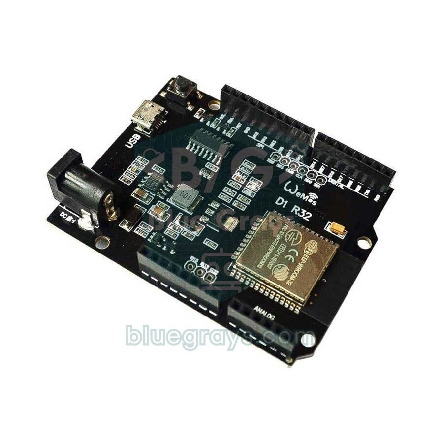
What is the ESPDuino-32? Compared with the Uno and the ESP32 DevKit
At the heart of the ESPDuino-32 is the ESP32-WROOM-32 module, the same one found on classic ESP32 boards. In software terms it's an ordinary ESP32: every sketch and library written for the ESP32 runs on it. The difference is the board design: the pins are routed to Uno headers, and the board adds a DC jack, a 3.3 V regulator and a USB-serial converter (usually a CH340). If you've never used an ESP32, you'll find the basics in What Is the ESP32?
| Feature | Arduino Uno R3 | ESPDuino-32 | ESP32 DevKit |
|---|---|---|---|
| Processor | ATmega328P, 8-bit, 16 MHz | ESP32, dual-core, 240 MHz | ESP32, dual-core, 240 MHz |
| RAM | 2 KB | 520 KB | 520 KB |
| Flash | 32 KB | 4 MB | 4 MB |
| Logic level | 5 V | 3.3 V | 3.3 V |
| Wireless | None | Wi-Fi + Bluetooth | Wi-Fi + Bluetooth |
| Analog inputs | 6 channels, 10-bit | 6 channels on the Uno header, 12-bit | Up to 18 channels, 12-bit |
| Size and shields | 68.6 × 53.4 mm, Uno shields | Same size as the Uno, takes shields | Fits a breadboard, no shields |
| USB chip | ATmega16U2 | Usually CH340 | CP2102 or CH340 |
So which one should you buy? If you own Uno shields, want to screw the board into an enclosure using the Uno mounting holes, or are following a book or course written for the Uno, the ESPDuino-32 makes life easier. If you work on a breadboard, want access to ESP32 pins that don't reach the Uno header, such as GPIO 32 and 33, or need a small device, the classic ESP32 DevKit is the better fit. The code is the same on both; only the pin numbers change.
ESPDuino-32 pinout: which GPIO is behind each Uno pin?
Even though the board is labelled D2, D3, A0 like an Uno, your code usually needs the GPIO number. The table below shows the ESP32 GPIO behind every Uno pin and what to watch out for. You can also look up the full ESP32 pin list in the Pinout tool.
| Uno pin | ESP32 GPIO | Status | Note |
|---|---|---|---|
| D0 (RX) | GPIO 3 | Avoid | USB serial line |
| D1 (TX) | GPIO 1 | Avoid | USB serial line |
| D2 | GPIO 26 | Safe | Can also be used as the DAC2 output |
| D3 | GPIO 25 | Safe | Can also be used as the DAC1 output |
| D4 | GPIO 17 | Safe | Also used as Serial2 TX |
| D5 | GPIO 16 | Safe | Also used as Serial2 RX |
| D6 | GPIO 27 | Safe | Touch input (T7) |
| D7 | GPIO 14 | Use with care | Outputs a short PWM signal at boot |
| D8 | GPIO 12 | Use with care | Strapping pin: the board won't boot if it's HIGH at power-up |
| D9 | GPIO 13 | Safe | General-purpose input and output |
| D10 | GPIO 5 | Use with care | SPI SS; outputs a short PWM signal at boot |
| D11 | GPIO 23 | Safe | SPI MOSI |
| D12 | GPIO 19 | Safe | SPI MISO |
| D13 | GPIO 18 | Safe | SPI SCK; no LED here, unlike the Uno |
| A0 | GPIO 2 | Use with care | ADC2 (no readings while Wi-Fi is on), onboard LED, strapping pin |
| A1 | GPIO 4 | Use with care | ADC2 (no readings while Wi-Fi is on) |
| A2 | GPIO 35 | Input only | ADC1, works alongside Wi-Fi |
| A3 | GPIO 34 | Input only | ADC1, works alongside Wi-Fi |
| A4 | GPIO 36 (VP) | Input only | ADC1; not SDA as on the Uno |
| A5 | GPIO 39 (VN) | Input only | ADC1; not SCL as on the Uno |
| SDA | GPIO 21 | Safe | I2C data line |
| SCL | GPIO 22 | Safe | I2C clock line |
There are two more analog traps. First, A0 (GPIO 2) and A1 (GPIO 4) belong to the ESP32's ADC2 unit, which can't take readings while Wi-Fi is on; in Wi-Fi projects, connect analog sensors to A2–A5 (ADC1). Second, the ESP32's ADC is 12-bit: analogRead() returns 0–4095 instead of 0–1023, and full scale is about 3.3 V, not 5 V. Maths such as "value × 5.0 / 1023" in Uno sketches has to change accordingly; better still, use analogReadMilliVolts(), which returns a calibrated result in millivolts.
The 3.3 V trap: do Uno shields work on the ESPDuino-32?
A shield that fits isn't necessarily a shield that works. A shield causes trouble on the ESPDuino-32 in one of three ways: it sends a 5 V signal into the ESP32 and damages the pin, it expects 5 V logic and doesn't always see 3.3 V as HIGH, or it relies on the input-only pins A2–A5 for something that needs an output. Because the board's 5V pin supplies 5 V just like the Uno, the shield itself gets powered; the problems always show up on the signal pins. Here's how the common shields fare:
| Shield | Status | Why |
|---|---|---|
| CNC Shield V3 (A4988 / DRV8825) | Usually works | STEP and DIR land on output-capable GPIOs; ESP32 versions of GRBL ship with a ready-made pin map for this board |
| Relay shield | Usually works | The relays are powered from the 5V pin, and the driver transistor still switches on with a 3.3 V signal |
| Data logger shield (SD card + RTC) | Partly | An SD card on D10–D13 works, because those are the ESP32's SPI pins; the RTC fails if its I2C lines only go to A4/A5 |
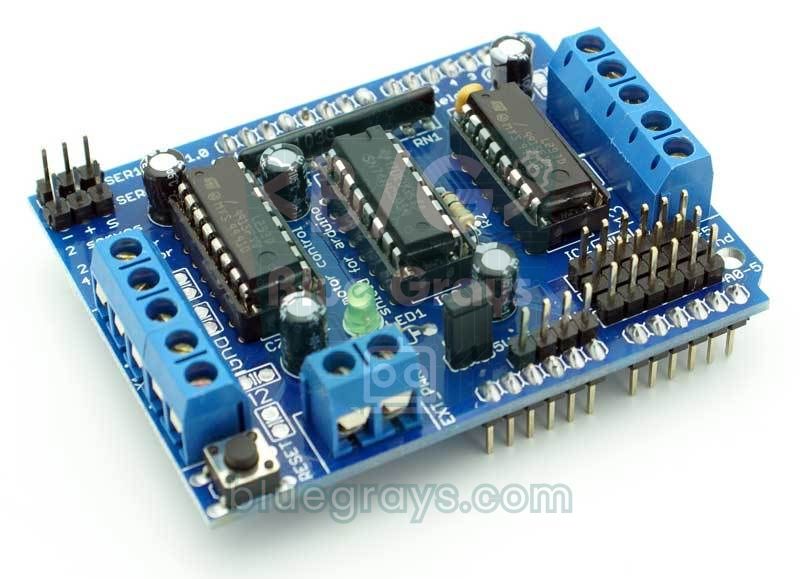
| L293D motor shield | Unreliable | The 74HC595 at 5 V barely reads 3.3 V inputs, and its data line is on D8 (GPIO 12), which can also break booting |
| LCD Keypad shield | Risky | The buttons reach A0 through a resistor ladder tied to 5 V, so GPIO 2 sees 5 V when no button is pressed |
| 2.4 inch parallel TFT shield | Doesn't work | Its control lines are on A0–A4; A2, A3 and A4 are input-only, so they can't drive the display |
| Older shields that take I2C only from A4/A5 | Doesn't work | On the ESPDuino-32, I2C lives on the separate SDA/SCL pins (GPIO 21/22) |
Strapping pins: watch D8 and A0
When it powers up, the ESP32 checks the level of a few pins to decide how to start. Two of them reach the Uno header on the ESPDuino-32. If D8 (GPIO 12) is HIGH at boot, the ESP32 tries to start its flash memory at the wrong voltage and the board won't boot. A0 (GPIO 2) has to be floating or LOW while you upload code. If you've connected a module or shield with a pull-up on D8 and the board won't start, that's your first suspect. D7 (GPIO 14) and D10 (GPIO 5) also output a short PWM signal at boot, so a relay on those pins may click briefly at power-up.
Setting up the ESPDuino-32 in the Arduino IDE
- Install Espressif's esp32 board package in the Arduino IDE; the steps are in What Is the ESP32?
- Connect the board over USB. If no port shows up, install the driver for its USB chip (usually a CH340) and make sure your cable carries data.
- Under Tools > Board > esp32, choose WEMOS D1 R32: in this definition the names D2–D13 and A0–A5 match the labels on the board exactly. DOIT ESPduino32 or ESP32 Dev Module also work, but then you have to use GPIO numbers only.
- Select the board's port; if uploads fail at an Upload Speed of 921600, drop it to 115200.
- Click Upload and open the Serial Monitor at 115200 baud. If the board won't enter upload mode, see the fixes in ESP32 Failed to Connect.
First test: onboard LED, D13 and an analog reading
The board's blue onboard LED is on GPIO 2, not on D13 as on the Uno. The sketch below takes turns lighting the onboard LED and an LED wired to D13 (GPIO 18) through a 220 Ω resistor, and prints the value of a potentiometer on A2 (GPIO 35) to the Serial Monitor. Connect the potentiometer's outer legs to 3V3 and GND, not to 5V; the middle leg goes to A2.
1// ESPDuino-32: Uno adları yerine GPIO numaraları / GPIO numbers instead of Uno pin names
2const int ONBOARD_LED = 2;    // kart üstü mavi LED (A0 ile aynı pin) / onboard blue LED (same pin as A0)
3const int LED_D13 = 18;       // Uno D13 = GPIO 18
4const int POT_A2 = 35;        // Uno A2 = GPIO 35 (ADC1, yalnız giriş / input only)
5
6void setup() {
7  Serial.begin(115200);
8  pinMode(ONBOARD_LED, OUTPUT);
9  pinMode(LED_D13, OUTPUT);
10  analogReadResolution(12);                      // 0–4095 (varsayılan / default)
11}
12
13void loop() {
14  int raw = analogRead(POT_A2);                  // 0–4095, Uno'daki gibi 0–1023 değil / not 0–1023 like the Uno
15  int mv = analogReadMilliVolts(POT_A2);         // kalibre edilmiş mV / calibrated millivolts
16  Serial.printf("A2 ham / raw: %d  gerilim / voltage: %d mV\n", raw, mv);
17
18  digitalWrite(ONBOARD_LED, HIGH);               // LED'ler sırayla / LEDs take turns
19  digitalWrite(LED_D13, LOW);
20  delay(500);
21  digitalWrite(ONBOARD_LED, LOW);
22  digitalWrite(LED_D13, HIGH);
23  delay(500);
24}
First Wi-Fi project: control an LED from your phone
Now let's see what really sets the board apart from the Uno. The sketch below connects the ESPDuino-32 to your home network and starts a small web server. Type the IP address shown in the Serial Monitor into the browser of a phone on the same network and you'll see a button that switches the LED on D13 and the potentiometer reading on A2 in millivolts. We put the potentiometer on A2 on purpose: A0 and A1 can't read analog values while Wi-Fi is on.
1#include <WiFi.h>
2#include <WebServer.h>
3
4const char* WIFI_SSID = "AgAdi";          // Wi-Fi adın / your Wi-Fi name
5const char* WIFI_PASS = "Sifre123";       // Wi-Fi şifren / your Wi-Fi password
6
7const int LED_PIN = 18;                   // Uno D13 = GPIO 18
8const int POT_PIN = 35;                   // Uno A2 = GPIO 35 (ADC1: Wi-Fi ile çalışır / works with Wi-Fi)
9
10WebServer server(80);
11bool ledOn = false;
12
13String page() {
14  String html = "<!DOCTYPE html><html><head><meta charset='utf-8'>";
15  html += "<meta name='viewport' content='width=device-width,initial-scale=1'>";
16  html += "<title>ESPDuino-32</title></head>";
17  html += "<body style='font-family:sans-serif;text-align:center'><h1>ESPDuino-32</h1>";
18  html += "<p>LED (D13): <b>" + String(ledOn ? "ON" : "OFF") + "</b></p>";
19  html += "<p><a href='/toggle'><button style='font-size:24px;padding:12px 32px'>LED</button></a></p>";
20  html += "<p>A2: " + String(analogReadMilliVolts(POT_PIN)) + " mV</p>";
21  html += "</body></html>";
22  return html;
23}
24
25void handleRoot() {
26  server.send(200, "text/html", page());
27}
28
29void handleToggle() {
30  ledOn = !ledOn;
31  digitalWrite(LED_PIN, ledOn ? HIGH : LOW);
32  server.sendHeader("Location", "/");      // ana sayfaya dön / back to the main page
33  server.send(303);
34}
35
36void setup() {
37  Serial.begin(115200);
38  pinMode(LED_PIN, OUTPUT);
39
40  WiFi.mode(WIFI_STA);
41  WiFi.begin(WIFI_SSID, WIFI_PASS);
42  Serial.print("Baglaniyor / Connecting");
43  while (WiFi.status() != WL_CONNECTED) {  // bağlanana kadar bekle / wait until connected
44    delay(500);
45    Serial.print(".");
46  }
47  Serial.println();
48  Serial.print("IP: ");
49  Serial.println(WiFi.localIP());          // bu adresi telefonda aç / open this address on your phone
50
51  server.on("/", handleRoot);
52  server.on("/toggle", handleToggle);
53  server.begin();
54}
55
56void loop() {
57  server.handleClient();                   // gelen istekleri işle / handle incoming requests
58}
The sketch defines two addresses: / sends the main page, and /toggle flips the LED and redirects the browser back to the main page. Every time you reload the page, the potentiometer is read again. For a live interface that updates without reloading, use the approach in ESP32 Async Web Server and WebSocket. If the board won't join your network, make sure it's a 2.4 GHz network; the ESP32 can't see 5 GHz networks.
Powering the board: USB, DC jack and the 3V3 pin
| Source | Voltage | Note |
|---|---|---|
| USB | 5 V | Enough for development and small circuits |
| DC jack | Usually 7–12 V (check the marking on your board) | The regulator gets warm; 9 V runs cooler than 12 V |
| VIN pin | The voltage on the DC jack | For powering the board from an external supply |
| 5V pin | 5 V output | Powers shields and 5 V modules; remember to bring their signals down to 3.3 V |
| 3V3 pin | 3.3 V output | For sensors; don't connect motors or long LED strips |
While the ESP32 transmits over Wi-Fi it can draw bursts of close to 250 mA. A weak USB cable or port lets the voltage dip at those moments and the board resets with "Brownout detector was triggered". If that happens, use a short, good-quality cable or power the board from the DC jack; the details are in ESP32 Brownout and Guru Meditation.
Common mistakes and how to fix them
- An Uno sketch doesn't work: the pin numbers were written for the Uno. pinMode(13, OUTPUT) on the ESPDuino-32 drives GPIO 13, which is D9, not D13; look up the GPIO number in the table.
- analogRead is always 4095 or always 0: the sensor is powered from 5 V and its output goes above 3.3 V, or the sensor is on an ADC2 pin (A0, A1) while Wi-Fi is on.
- The I2C display isn't detected: it's wired to A4/A5; move the wires to the SDA/SCL pins (GPIO 21/22).
- The board won't boot or keeps resetting: something on D8 (GPIO 12) pulls the pin HIGH at power-up; move that part to another pin.
- The board or a part gets warm once the shield is on: the shield is sending 5 V into a pin; unplug the board straight away and bring that line down with a divider or a level shifter.
- SoftwareSerial or the Servo library won't compile: use the ESP32 equivalents instead of the AVR-only libraries: the hardware serial port Serial2 and ESP32Servo.
The ESPDuino-32 is the most familiar way to move from the Uno to the ESP32: the same footprint and the same headers, but a clock speed 15 times higher and wireless connectivity. Keep Arduino Uno Pinout open next to you to remember the differences. All the ESP32 projects in the BlueGrays app run on this board too, so you can build the LED, traffic light, Wi-Fi connection and web server projects step by step with their circuit diagrams and code; just map the pins using the table above.
Frequently asked questions
Is the ESPDuino-32 the same as the WEMOS D1 R32?
For practical purposes, yes. Both put an ESP32-WROOM-32 module on an Uno-sized board with the same pin mapping on the Uno headers. The Arduino IDE has separate definitions for each, and the WEMOS D1 R32 one is handier because it links the D and A labels on the board to the right GPIOs.
Can I use Arduino Uno shields on the ESPDuino-32?
They fit physically, but whether they work depends on the shield. Shields that don't send 5 V signals to the ESP32, don't use A2–A5 as outputs and don't take I2C only from A4/A5 usually work; LCD Keypad and parallel TFT shields don't work without modifications.
Does the ESPDuino-32 work with 5 V?
The board is powered with 5 V from USB or the 5V pin and can take a higher voltage through the DC jack. Its signal pins, however, run at 3.3 V and aren't 5 V tolerant, so sensors with 5 V outputs need a voltage divider or a level shifter.
Which pin is the onboard LED on the ESPDuino-32?
The blue onboard LED is wired to GPIO 2, which also appears on the board as A0. There's no LED on D13 like on the Uno, and the LED_BUILTIN constant returns 2.
Which board should I select for the ESPDuino-32 in the Arduino IDE?
Choose WEMOS D1 R32 if you want to use the Uno labels (such as D2 or A0) in your code. DOIT ESPduino32 or ESP32 Dev Module upload code just as well, but with those you have to write pins as GPIO numbers.
Why doesn't analogRead work on my ESPDuino-32?
The most common reason is that the sensor is on A0 or A1 while Wi-Fi is on; those pins belong to ADC2, which can't read while Wi-Fi is active. Move the sensor to A2–A5 (ADC1), and remember the result runs from 0 to 4095 with a full scale of about 3.3 V.
Projects to build after reading this
See all projects
LED Blink with ESP32
Teaches basic GPIO output usage with ESP32. We achieve a blinking effect by turning an LED on and off from a digital pin. ESP32 version of the classic blink project on Arduino UNO; the basic blink commands in the Arduino environment are the same, but the ESP32's pin layout and 3.3 V GPIO levels differ from those of the Arduino UNO.

ESP32 Built-in LED Blink
Blinking the built-in blue LED on the ESP32 DevKit V1. No external components required! The first project you should try when you buy an ESP32. GPIO 2 is connected to the built-in LED.

ESP32 Traffic Light
Real traffic light simulation with 3 LEDs red-yellow-green. Timings close to real traffic logic: red long, yellow short, green long. Classic example of sequential GPIO control.

Reading Light Intensity with the ESP32 LDR Module
Real-time monitoring of the LDR module's raw ADC value and relative light percentage calculated from dark and light reference values in the Serial Monitor. This percentage is not a lux measurement. Teaches the module’s calibration logic. It is ideal to complete this before Project 10, as it is used to determine the threshold value.

ESP32 LED Brightness Control with a Potentiometer (Analog → PWM)
In this project, we control the brightness of an LED analogically using a potentiometer. The ESP32's ADC pin reads the 0-3.3V voltage from the potentiometer, and this value is then converted into a PWM (Pulse Width Modulation) signal and sent to the LED. As a result, as you turn the potentiometer, the LED gradually brightens and dims. With Arduino Core 3.0+, analogWrite() can be used directly; on the ESP32-S2/S3, the ADC resolution is fixed at 12-bit.

ESP32 Wi-Fi STA Connection (with LCD Screen)
In this project, we connect the ESP32 to the home Wi-Fi network in Station (STA) mode in a secure, fault-tolerant manner. We store the SSID and password in a separate secrets.h file to prevent leaking to Git, set up an auto-reconnect mechanism, and display the RSSI signal level and IP address on an I2C LCD screen. The internal LED works as a status indicator. It is a production-grade connection manager.

ESP32 Asynchronous Web Server (with IP Display on LCD)
In this project, we’re turning the ESP32 into an asynchronous web server that you can control from your phone or computer on the same Wi-Fi network. Thanks to the ESPAsyncWebServer library, the server can process multiple requests simultaneously (unlike the classic WebServer.h, which blocks on a single request). You’ll be able to open the ESP32’s IP address in a browser and click the ON/OFF buttons (the /on and /off routes) to turn the LED connected to GPIO 5 on and off.

ESP32 mDNS: Accessing the Device via bluegrays-esp.local (with LCD Screen)
In this project we add an mDNS (Multicast DNS) service to the ESP32, so you reach it by a readable host name like bluegrays-esp.local instead of an IP address. Even if the IP assigned by DHCP changes, the device always answers to the same name. A small web server on the board lets you control the LED from your browser at http://bluegrays-esp.local/.