
Logic Level Converter: Safely Connecting 3.3 V and 5 V Devices
What is a logic level converter? Why ESP32 and Pico pins can't take 5 V, VIH/VIL thresholds, voltage dividers, BSS138 for I2C, 74HCT chips and a module table.
A logic level converter is a small circuit that lets a board running on 3.3 V (ESP32, Raspberry Pi Pico, ESP8266) talk safely to a board or module running on 5 V (Arduino Uno, I2C LCD, HC-SR04, WS2812B). Connecting a 5 V output straight to a 3.3 V pin can damage the pin slowly or instantly; in the other direction, a 3.3 V signal sometimes isn't even seen as a "1" by a 5 V input. Knowing when you need a converter, and which one is enough, removes the mysterious faults in half of all mixed-voltage projects.
In this article you'll first see what the VIH and VIL thresholds mean and why ESP32 and Pico pins can't take 5 V. Then we'll look at three solutions with examples: one-way conversion with a two-resistor voltage divider, a bidirectional BSS138 MOSFET converter for I2C, and 74HCT chips for fast signals such as WS2812B or SPI. At the end there's a table showing which modules work directly at 3.3 V, plus a list of common mistakes.
What are 3.3 V and 5 V logic levels?
A digital pin only knows 0 and 1, but in the real world the voltage can be anything between 0 and the supply. That's why every chip's datasheet gives four thresholds. VIH (input HIGH) is the lowest voltage the input is guaranteed to read as 1. VIL (input LOW) is the highest voltage guaranteed to read as 0. The region in between is undefined: the chip may read either 0 or 1 there. On the output side, VOH is the lowest voltage the pin guarantees when driving HIGH, and VOL the highest voltage it guarantees when driving LOW. For two chips to talk reliably, the sender's VOH must sit safely above the receiver's VIH, and the sender's VOL safely below the receiver's VIL. You can see how gates make decisions with these thresholds in the logic gates article and try them in the logic gate tool.
| Chip (supply) | VIL (max) | VIH (min) | VOL (max) | VOH (min) | Pin absolute max |
|---|---|---|---|---|---|
| ATmega328P, Arduino Uno (5 V) | 1.5 V (0.3 × VCC) | 3.0 V (0.6 × VCC) | 0.9 V | 4.2 V | 5.5 V |
| ESP32 (3.3 V) | 0.83 V (0.25 × VDD) | 2.48 V (0.75 × VDD) | 0.33 V | 2.64 V | 3.6 V |
| RP2040, Raspberry Pi Pico (3.3 V) | 0.8 V | 2.0 V | 0.5 V | About 2.6 V | 3.8 V |
| 74HC series (5 V) | 1.5 V | 3.5 V | 0.1 V | 4.4 V | 5.5 V |
| 74HCT series (5 V) | 0.8 V | 2.0 V | 0.1 V | 4.4 V | 5.5 V |
Three important conclusions come out of the table. First, a 5 V Uno's HIGH output (4.2–5 V) clearly exceeds the ESP32's 3.6 V and the Pico's 3.8 V limit, so in that direction conversion is a must. Second, the ESP32's 3.3 V HIGH output usually clears the Uno's 3.0 V VIH threshold, but the lowest VOH the datasheet guarantees is 2.64 V; so the connection often works but sits at the edge as the wire gets longer or the pin gets loaded. Third, a 74HC chip powered from 5 V, an I2C expander with a 0.7 × VCC threshold such as the PCF8574, or a WS2812B LED won't reliably count anything below 3.5 V as HIGH; for these chips a 3.3 V signal really isn't enough. The 74HCT series has a VIH of 2.0 V, which is why it's one of the cleanest ways to turn 3.3 V into 5 V.
Why can't ESP32 and Pico pins take 5 V?
Every input pin on a 3.3 V chip has small protection diodes that connect the pin to the 3.3 V rail and to GND. They're designed to absorb very short pulses such as static discharge, not continuous current. When you apply 5 V to the pin, the upper diode conducts and current flows from the 5 V source into the 3.3 V rail. If the source's internal resistance is low, that current reaches tens of milliamps and destroys the diode and the circuitry around the pin by heating them. If the current is smaller, the pin doesn't die right away, but the chip wears out over time, and the 3.3 V rail can even be pushed up so the board starts powering itself through the pin: you unplug the power cable and the ESP32's LED keeps glowing dimly. The ESP32 datasheet gives a pin limit of supply + 0.3 V (about 3.6 V), and the RP2040's supply + 0.5 V (about 3.8 V). "I tried it once and it didn't break" doesn't mean the pin is 5 V tolerant.
What do you need in which case?
| Case | Example | Solution |
|---|---|---|
| 5 V output → 3.3 V input | Uno TX → ESP32 RX, HC-SR04 ECHO → Pico | Voltage divider (slow signals) or a 74LVC buffer (fast signals) |
| 3.3 V output → 5 V input (VIH around 3 V) | ESP32 TX → Uno RX | Often works directly; a 74HCT for guaranteed margins |
| 3.3 V output → 5 V input (VIH 3.5 V) | ESP32 → WS2812B, a 5 V 74HC chip | A buffer such as the 74HCT125 / 74AHCT125 |
| Bidirectional open-drain line | I2C (SDA, SCL), 1-Wire | BSS138 MOSFET converter |
| Bidirectional fast push-pull line | Parallel data bus | 74LVC245 with a direction pin, or TXS0108E |
One-way conversion with a voltage divider (5 V → 3.3 V)
The simplest way to bring a 5 V output into a 3.3 V input is two resistors. The signal enters through the top resistor R1, the midpoint goes to the 3.3 V pin, and the bottom resistor R2 goes to GND. The output is Vout = 5 V × R2 / (R1 + R2); making R2 twice R1 brings 5 V down to 3.33 V. A divider only works one way: from the higher voltage to the lower, so it can't be used on bidirectional lines where the 3.3 V side has to answer. Its speed is limited too, because the divider's output resistance forms a small RC filter with the pin's capacitance and rounds off the signal edges. Use the voltage divider calculator to pick values, and the voltage divider article for the full explanation.
| R1 (signal side) | R2 (GND side) | Output at 5 V | Output resistance | Good for |
|---|---|---|---|---|
| 1 kΩ | 2 kΩ (two 1 kΩ in series) | 3.33 V | 667 Ω | Most jobs including fast signals; draws 1.7 mA when HIGH |
| 2.2 kΩ | 3.3 kΩ | 3.00 V | 1.3 kΩ | Safest margin; UART, HC-SR04 ECHO |
| 10 kΩ | 20 kΩ | 3.33 V | 6.7 kΩ | Low current; UART up to 115200 baud and slow signals |
| 4.7 kΩ | 10 kΩ | 3.40 V | 3.2 kΩ | Borderline; if the 5 V rail rises to 5.25 V it gives 3.57 V, not recommended |
Example: UART between an Arduino Uno and an ESP32
In projects where the Uno reads the sensors and the ESP32 carries the data to the internet over Wi-Fi, the two boards talk over UART. Because the Uno's TX line outputs 5 V, it goes to the ESP32's RX pin through a 1 kΩ + 2 kΩ divider. The ESP32's 3.3 V TX line can go straight to the Uno's RX pin, since the Uno treats anything above 3.0 V as HIGH. To keep the Uno's USB serial port (D0, D1) free for the computer, the Uno side uses SoftwareSerial on D10 and D11; on the ESP32, the second hardware serial port Serial2 runs on GPIO 16 (RX) and 17 (TX). The GNDs of the two boards must be connected together.
1// Arduino Uno: SoftwareSerial ile ESP32'ye veri gönder / send data to the ESP32 with SoftwareSerial
2// Uno D11 (TX, 5 V) -> 1k -> ESP32 GPIO 16 ; GPIO 16 -> 2k -> GND
3// ESP32 GPIO 17 (TX, 3,3 V) -> Uno D10 (RX) doğrudan / directly ; GND <-> GND
4#include <SoftwareSerial.h>
5
6SoftwareSerial link(10, 11);   // RX, TX
7
8void setup() {
9  Serial.begin(9600);          // bilgisayar / computer
10  link.begin(9600);            // ESP32 hattı / ESP32 line
11}
12
13void loop() {
14  int raw = analogRead(A0);
15  link.print(F("A0="));
16  link.println(raw);           // ör. / e.g. "A0=512"
17
18  unsigned long start = millis();
19  while (millis() - start < 1000) {          // 1 sn cevap bekle / wait 1 s for a reply
20    if (link.available()) {
21      String reply = link.readStringUntil('\n');
22      Serial.print(F("ESP32: "));
23      Serial.println(reply);
24    }
25  }
26}1// ESP32: Serial2 ile Uno'dan gelen satırları oku ve cevap ver / read lines from the Uno on Serial2 and reply
2const int RX2_PIN = 16; // bölücünün orta noktası / divider midpoint
3const int TX2_PIN = 17; // Uno D10'a doğrudan / straight to Uno D10
4
5void setup() {
6 Serial.begin(115200);
7 Serial2.begin(9600, SERIAL_8N1, RX2_PIN, TX2_PIN);
8}
9
10void loop() {
11 if (Serial2.available()) {
12 String line = Serial2.readStringUntil('\n');
13 line.trim();
14 Serial.print("Uno: ");
15 Serial.println(line);
16 Serial2.print("OK "); // 3,3 V çıkış Uno için yeterli / 3.3 V output is enough for the Uno
17 Serial2.println(line.length());
18 }
19}Before uploading, measure the divider's midpoint with a multimeter: with the Uno running and not sending anything, you should see about 3.3 V, because a UART line idles HIGH. If the Uno's Serial Monitor shows a line such as "ESP32: OK 6" every second, communication is working in both directions. At 9600 baud one bit lasts 104 µs, while the delay introduced by the 1 kΩ + 2 kΩ divider is in the nanosecond range, so speed isn't a concern at all.
Example: connecting an HC-SR04 to a Raspberry Pi Pico
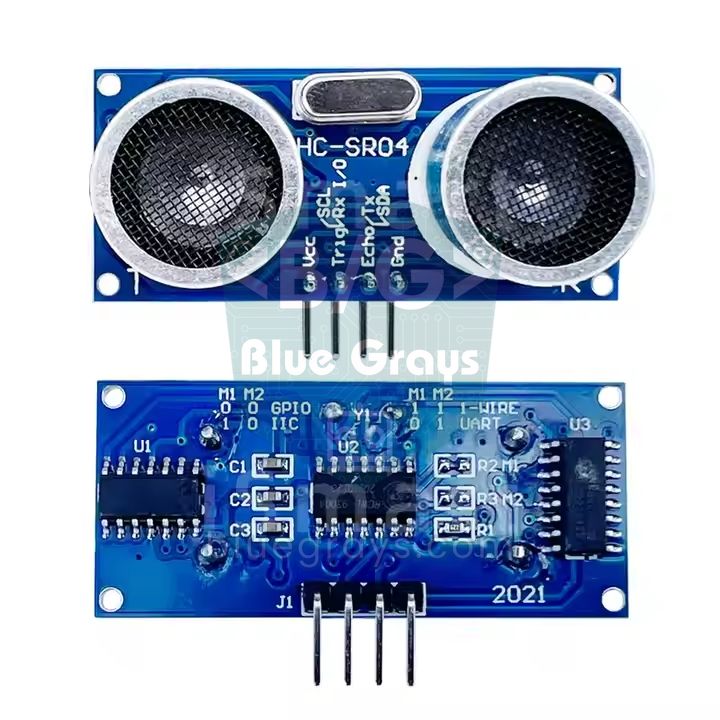
The HC-SR04 only works reliably on 5 V. If you power the Pico from USB, connect the sensor's VCC to the Pico's VBUS pin (pin 40). The TRIG input picks up the Pico's 3.3 V pulse without trouble, so it goes straight to GP15. ECHO, however, returns a 5 V pulse; a 1 kΩ resistor goes between ECHO and GP14, and a 2 kΩ resistor between GP14 and GND. The code measures the length of the ECHO pulse in microseconds with time_pulse_us and converts it to distance using the speed of sound in air (about 343 m/s).
1# Raspberry Pi Pico + HC-SR04 (ECHO bölücüyle) / Raspberry Pi Pico + HC-SR04 (ECHO through a divider)
2# VCC -> VBUS (pin 40), GND -> GND, TRIG -> GP15, ECHO -> 1k -> GP14 -> 2k -> GND
3from machine import Pin, time_pulse_us
4import time
5
6trig = Pin(15, Pin.OUT)
7echo = Pin(14, Pin.IN)
8
9
10def distance_cm():
11    trig.value(0)
12    time.sleep_us(2)
13    trig.value(1)                      # 10 µs tetik darbesi / 10 µs trigger pulse
14    time.sleep_us(10)
15    trig.value(0)
16    t = time_pulse_us(echo, 1, 30000)  # en fazla 30 ms bekle / wait at most 30 ms
17    if t < 0:
18        return None                    # yankı yok / no echo
19    return t * 0.0343 / 2              # gidiş-dönüş / round trip
20
21
22while True:
23    d = distance_cm()
24    if d is None:
25        print("Olcum yok / No echo")
26    else:
27        print("Mesafe / Distance: {:.1f} cm".format(d))
28    time.sleep(0.5)
The BSS138 bidirectional level converter
Most of the small boards sold as "4-channel logic level converters" have one BSS138 N-channel MOSFET and two 10 kΩ pull-up resistors per channel. The circuit is extremely simple: the MOSFET's gate is tied to 3.3 V (LV), its source goes to the low-voltage side and its drain to the high-voltage side. Each side's own pull-up resistor pulls the line up to that side's supply. This arrangement is designed for open-drain lines such as I2C, which only ever pull the line to 0 and leave the 1 level to the pull-up resistors, and it works in both directions on its own; there's no direction pin telling it which side is talking.
- Both sides idle: The MOSFET's gate and source are both at 3.3 V, the voltage between them is zero and the MOSFET is off. Each side is pulled HIGH by its own resistor: the LV side to 3.3 V, the HV side to 5 V.
- The 3.3 V side pulls LOW: The source drops to 0 V; since the gate stays at 3.3 V, the gate-source voltage becomes 3.3 V and the MOSFET turns on. The HV side is pulled LOW through the MOSFET.
- The 5 V side pulls LOW: The body diode inside the MOSFET conducts and pulls the source down to about 0.7 V. Once the gate-source voltage reaches about 2.6 V, the MOSFET switches fully on and the LV side goes fully LOW as well.
| Module pin | Connect to | Note |
|---|---|---|
| LV | The 3.3 V board's 3V3 pin | Low-side supply and the MOSFETs' gate voltage |
| HV | 5 V source (Uno 5V or ESP32 VIN) | High-side pull-up supply |
| GND (two) | GND of both boards | A common ground is required |
| LV1–LV4 | ESP32 or Pico pins | 3.3 V side signals |
| HV1–HV4 | Pins of the 5 V module | Each pairs with the LV pin of the same number |
Example: connecting an ESP32 to a 5 V I2C LCD
16x2 character LCDs don't give enough contrast unless they're powered from 5 V, and the PCF8574 I2C backpack on the back pulls SDA and SCL up to 5 V with 4.7 kΩ resistors. On top of that, the PCF8574's VIH threshold is 0.7 × VCC, which is 3.5 V at 5 V; the ESP32's 3.3 V falls below it. So using a BSS138 converter between the I2C LCD and the ESP32 both protects the pins and makes communication reliable. Wire it like this: the ESP32's 3V3 pin to LV, its VIN pin (5 V from USB) to HV and to the LCD's VCC, all GNDs together; GPIO 21 to LV1 and HV1 to the LCD's SDA; GPIO 22 to LV2 and HV2 to the LCD's SCL. If the scanner code below finds the LCD (usually at 0x27 or 0x3F), the converter is working.
1// ESP32 I2C tarayıcı: BSS138 dönüştürücü üzerinden 5 V'luk cihazları bul
2// ESP32 I2C scanner: find 5 V devices through a BSS138 converter
3// GPIO 21 -> LV1 / HV1 -> SDA ; GPIO 22 -> LV2 / HV2 -> SCL ; 3V3 -> LV ; VIN (5 V) -> HV
4#include <Wire.h>
5
6const int SDA_PIN = 21;
7const int SCL_PIN = 22;
8
9void setup() {
10  Serial.begin(115200);
11  Wire.begin(SDA_PIN, SCL_PIN);
12  Wire.setClock(100000);       // 100 kHz, BSS138 için rahat hız / comfortable speed for the BSS138
13}
14
15void loop() {
16  int found = 0;
17  for (byte addr = 1; addr < 127; addr++) {
18    Wire.beginTransmission(addr);
19    if (Wire.endTransmission() == 0) {      // 0 = ACK, cihaz var / device present
20      Serial.printf("Cihaz / Device: 0x%02X\n", addr);
21      found++;
22    }
23  }
24  if (found == 0) Serial.println("Cihaz yok / No device found");
25  Serial.println("---");
26  delay(3000);
27}
74HCT chips: fast one-way signals
When a divider or a BSS138 is too slow, the professional solution is a buffer chip. The 74HCT series runs on 5 V but its input threshold is TTL-compatible (VIH = 2.0 V), so it easily sees the 3.3 V signal from an ESP32 or Pico as HIGH and outputs a full 5 V signal with sharp edges. The most common use is the data line of WS2812B strips: the ESP32 pin goes to the input of a 74AHCT125, and its output goes through a 330 Ω resistor to the strip's DIN; the 74AHCT125's OE (enable) pin is tied to GND. For the opposite direction, bringing a fast 5 V signal down to 3.3 V, you use a 74LVC125 or 74LVC245 powered from 3.3 V; the inputs of these chips tolerate up to 5.5 V regardless of their own supply.
| Solution | Supply | Direction | Channels | Typical job |
|---|---|---|---|---|
| 74AHCT125 / 74HCT125 | 5 V | 3.3 V → 5 V | 4 | WS2812B data, SPI, MAX7219 |
| 74HCT245 | 5 V | 3.3 V → 5 V | 8 | Parallel data bus, many outputs |
| 74LVC125 / 74LVC245 | 3.3 V | 5 V → 3.3 V | 4 / 8 | Fast 5 V sensor outputs, SD card modules |
| BSS138 module | 3.3 V and 5 V | Bidirectional | 4 | I2C, 1-Wire, slow UART |
| Voltage divider | None | 5 V → 3.3 V | 1 | UART RX, HC-SR04 ECHO, buttons |
Which modules work directly at 3.3 V?
The table below sums up whether the modules most often used in ESP32 and Pico projects can connect to a 3.3 V board without a converter. You can power the "Yes" modules from the 3V3 pin and wire their signal pins directly. Still, modules sold under the same name can come in different versions; check whether the board has a regulator or level shifter, and if you're unsure, measure the voltage on the signal pin with a multimeter while VCC is on.
| Module | Direct at 3.3 V | Note |
|---|---|---|
| BME280 / BMP280 module | Yes | The chip itself wants 3.6 V at most; power it from 3V3 |
| DHT11 / DHT22 | Yes | 3.3–5.5 V; keep the cable short at 3.3 V |
| DS18B20 | Yes | 3.0–5.5 V; 4.7 kΩ pull-up to 3.3 V |
| 0.96" OLED (SSD1306) | Yes | The module has a regulator; powering it from 3V3 keeps I2C at 3.3 V too |
| MPU6050 (GY-521) | Yes | The module's pull-ups go to VCC; power it from 3V3 |
| RC522 RFID | Yes, 3.3 V only | Powering it from 5 V destroys the module |
| nRF24L01 | Yes, 3.3 V only | Add a 10–100 µF capacitor on the supply |
| HC-SR04 | No | Power it from 5 V and divide ECHO down; the 3.3 V version is the HC-SR04P |
| I2C 16x2 LCD (PCF8574) | Partly | The LCD needs 5 V; use a BSS138 for SDA and SCL |
| WS2812B LED strip | Partly | Powered from 5 V; 3.3 V data is borderline, a 74AHCT125 is recommended |
| 5 V relay module | Partly | On active-LOW modules a 3.3 V HIGH may not fully release the relay; choose a 3.3 V trigger module |
| SG90 servo | Signal yes | Power the motor from 5 V; a 3.3 V PWM signal is usually enough |
Common mistakes and how to fix them
| Symptom | Likely cause | Fix |
|---|---|---|
| The BSS138 converter doesn't work at all | LV and HV supplies not connected, or swapped | Feed 3.3 V to LV and 5 V to HV; join the GNDs |
| The ESP32's LED glows dimly with USB unplugged | A 5 V signal is powering the board through a pin | Add a divider or converter on that line |
| Signal is distorted or rounded after the divider | Resistors too large for a fast line | Drop to 1 kΩ + 2 kΩ or use a 74LVC buffer |
| The first LED of a WS2812B strip flickers | 3.3 V data is below the 3.5 V VIH threshold | Convert to 5 V with a 74AHCT125 and add 330 Ω on the data line |
| I2C works sometimes, hangs other times | Pull-ups to 5 V and a high VIH threshold on the device | Use a BSS138 and slow down to 100 kHz |
| Relay never releases | Active-LOW relay module doesn't see 3.3 V as HIGH | Use a 3.3 V trigger module or a transistor driver |
| UART characters get garbled through the converter | No common GND | Connect the GNDs of both boards |
Logic level conversion may sound technical, but it comes down to three rules: always protect a line going from 5 V to 3.3 V, check the receiver's VIH threshold on a line going from 3.3 V to 5 V, and use a BSS138 on bidirectional lines such as I2C. With these rules you can comfortably combine an Arduino, an ESP32 and a Pico in the same project. In the BlueGrays app, every connection in the ESP32 and Raspberry Pi Pico projects is explained with pins that match the board's logic level and a step-by-step wiring diagram.
Frequently asked questions
Is the ESP32 5 V tolerant?
No. The ESP32 datasheet sets a maximum of supply + 0.3 V, about 3.6 V, for the GPIO pins. With 5 V applied, the pin's protection diodes conduct, current flows into the 3.3 V rail and the pin can fail over time or immediately. The fact that it seems to work for a while doesn't make it safe.
Can I connect an Arduino to an ESP32 without a level converter?
Partly. 3.3 V signals going from the ESP32 to the Arduino usually clear the Uno's 3.0 V threshold, so they can be connected directly. 5 V signals going from the Arduino to the ESP32, however, must pass through a voltage divider or a converter. In every case the GNDs of the two boards must be joined.
Which logic level converter should I use for I2C?
Because I2C lines are open-drain, a bidirectional BSS138 MOSFET converter is the best choice; it works without trouble at 100 and 400 kHz. Chips designed for I2C such as the PCA9306 do the same job. A voltage divider can't be used on I2C, because the line carries data in both directions.
Does a WS2812B work with the ESP32's 3.3 V data?
Often yes, but it isn't guaranteed. A WS2812B powered from 5 V expects at least 3.5 V on its data input, and 3.3 V is below that threshold; the first LED may flicker, especially with a longer wire or when the supply rises above 5 V. The reliable fix is a buffer such as the 74AHCT125 or 74HCT125 on the data line.
Should I use a voltage divider or a level converter module?
If you're bringing a one-way, slow signal down from 5 V to 3.3 V, such as UART RX or HC-SR04 ECHO, two resistors are enough and the cheapest solution. If the line is bidirectional (I2C) or you need to raise 3.3 V to 5 V, a divider won't help; use a BSS138 module or a 74HCT buffer. For very fast signals, buffer chips are the right choice.
What do HV and LV mean on a logic level converter?
HV (high voltage) is the high-voltage side and usually connects to 5 V, while LV (low voltage) is the low-voltage side and connects to 3.3 V. Pins HV1–HV4 go to the 5 V device's signals, and the matching LV1–LV4 pins go to the 3.3 V board's pins. The GNDs of both sides are joined at the module's GND pins.
Projects to build after reading this
See all projects
LED Blink with ESP32
Teaches basic GPIO output usage with ESP32. We achieve a blinking effect by turning an LED on and off from a digital pin. ESP32 version of the classic blink project on Arduino UNO; the basic blink commands in the Arduino environment are the same, but the ESP32's pin layout and 3.3 V GPIO levels differ from those of the Arduino UNO.

ESP32 LED Control with Push Button (Push)
The LED lights up when the button is pressed and turns off when released. Shows how the ESP32's digital input pin and internal pull-up resistor are used. The INPUT_PULLUP mode eliminates the need for an external resistor.

Reading Light Intensity with the ESP32 LDR Module
Real-time monitoring of the LDR module's raw ADC value and relative light percentage calculated from dark and light reference values in the Serial Monitor. This percentage is not a lux measurement. Teaches the module’s calibration logic. It is ideal to complete this before Project 10, as it is used to determine the threshold value.
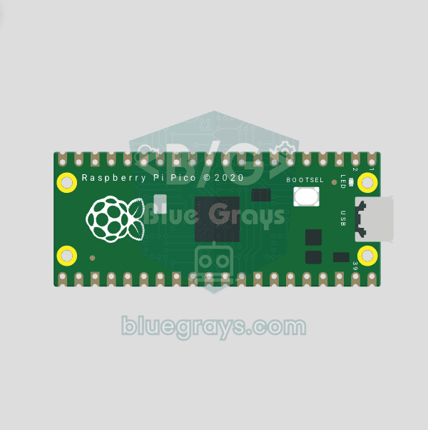
Raspberry Pi Pico Onboard LED Blink (Pico and Pico W)
The opening project of the Raspberry Pi Pico series! We blink the green onboard LED to verify the board works — a classic "Hello World" first experiment. NO external components, just Pico and USB cable. Code is written in MicroPython (the official language backed by Raspberry Pi Foundation). Learn machine.Pin class, Pin.OUT mode, led.on()/off() methods, and time.sleep() in Thonny IDE. Follow every toggle live in the Serial (REPL) output. Also perfect to verify

ESP32 I2C LCD Display (16x2)
In this project, we display text by connecting a 16x2 character LCD screen to the ESP32 via the I2C protocol. Thanks to I2C, we can control the screen using just two data pins (SDA and SCL), eliminating the waste of 6+ pins associated with a classic parallel connection. The code prints a fixed message on the first line and a counter that increments every second on the second line. Additionally, we run an I2C scanner at the start to print the display’s address to the Serial Monitor (typically 0x2

ESP32 HC-SR04 Ultrasonic Distance Sensor
The HC-SR04 ultrasonic sensor calculates distance by measuring the time it takes for the sound wave it emits to bounce off an object and return (Time of Flight). In this project, we will send a 10-microsecond pulse from the ESP32 to the sensor's TRIG pin and read the echo duration from the ECHO pin using pulseIn(). We will display the calculated distance in centimeters on a 16x2 I2C LCD. Since the HC-SR04 operates at 5V, a voltage divider is required on the ECHO pin—otherwise, the ESP32’s

ESP32 WS2812B NeoPixel Strip Control
WS2812B (NeoPixel) addressable LEDs are smart RGB LEDs that can be controlled in a daisy-chain configuration via a single data pin. In this project, we will control an 8-LED WS2812B strip using the Adafruit_NeoPixel library to create a smooth rainbow animation. While the ESP32’s 3.3V logic level works seamlessly with most WS2812B components, we’ll demonstrate a solution using a 470Ω series resistor and a 1000µF capacitor in case of instability. The animation is achieved by shifting the hue value
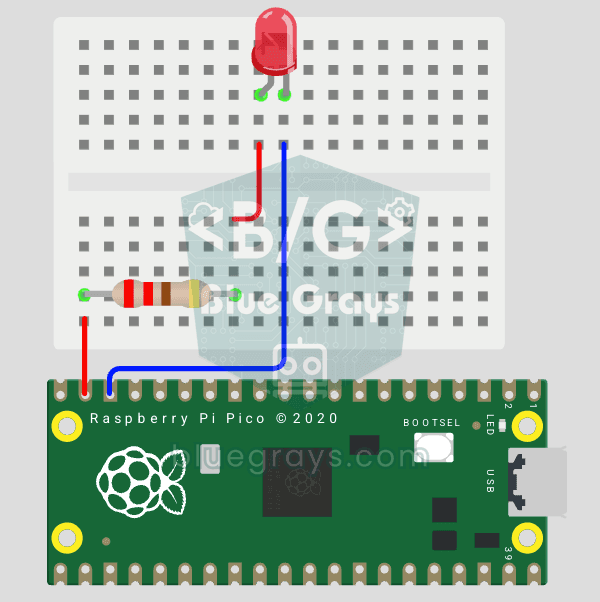
Raspberry Pi Pico: Controlling an External LED (Breadboard)
The next step after Pico’s built-in LED: connecting an external LED to the breadboard and controlling it via the GP14 pin. In this project, you’ll learn how to use any of the Pico’s general-purpose GPIO pins as an output, the LED’s polarity (long leg = anode/+, short leg = cathode/–), and why a current-limiting resistor (220Ω) is required. If you don’t include the resistor, excessive current will flow through the LED and it may burn out. The circuit is very simple: Pico GP14 → 220Ω resistor → LE