
ESP32 Brownout Detector Was Triggered and Guru Meditation Fix
ESP32 brownout detector was triggered and endless reboots: fix the power supply, cable and capacitor, read rst codes, Guru Meditation, Task WDT and backtraces.
The ESP32 brownout detector was triggered message means the board's supply voltage dipped below a safe limit for a moment and the chip restarted itself to stay safe. The problem is almost never in your code but on the power side: a weak USB port, a thin and long cable, an undersized regulator, or servos and LED strips powered from the same line as the ESP32. The second big reason an ESP32 keeps rebooting is a software crash; in that case the Serial Monitor shows lines such as Guru Meditation Error, task_wdt or Stack canary.
The good news: the ESP32 tells you why it restarted, as long as you know how to read its messages. In this guide you'll first learn to recognise the rst codes in the boot lines and the error messages, then fix brownouts for good with the right power supply, cable and capacitor. After that we'll cover Guru Meditation errors such as LoadProhibited and StoreProhibited, stack overflows, null pointers and watchdog timeouts, and you'll trace a crash down to the exact line of code with the ESP Exception Decoder. Finally we'll look at the strapping pins (GPIO0, 2, 12 and 15) that can break the boot process.
Why does the ESP32 keep rebooting? Read the message first
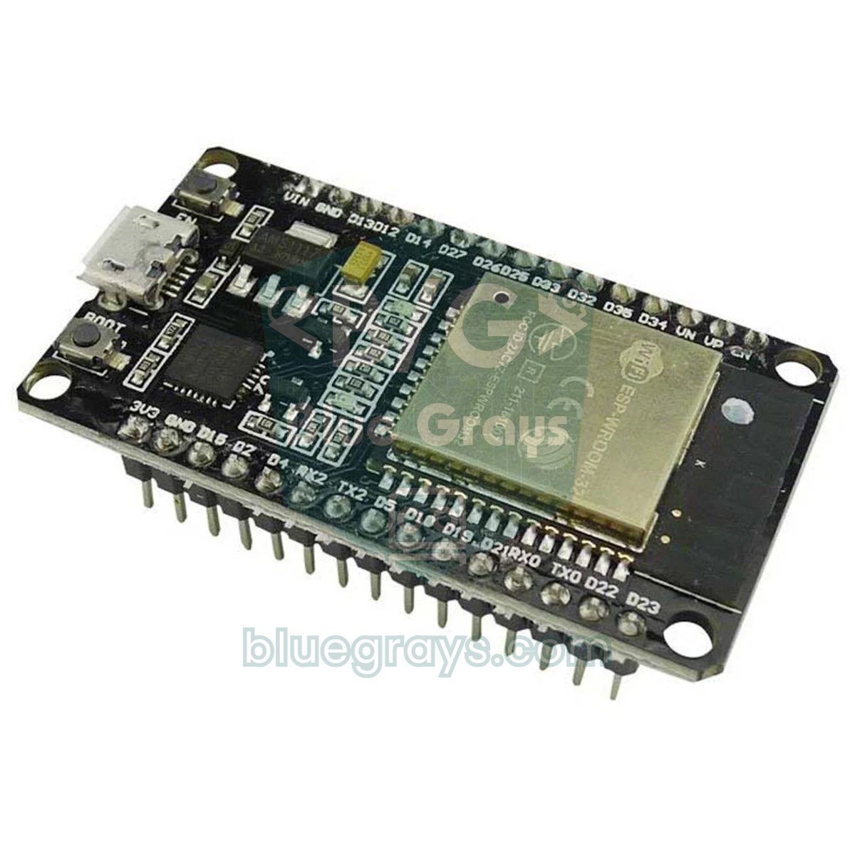
Before you start troubleshooting, open the Serial Monitor at 115200 baud and press the EN button on the board. On every boot, the ROM bootloader inside the ESP32 first prints a date line such as "ets Jun 8 2016 00:22:57", followed by a line like rst:0x1 (POWERON_RESET),boot:0x13 (SPI_FAST_FLASH_BOOT). The rst part tells you why the board restarted, the boot part shows which mode it started in. If the board is stuck in a loop, you'll find the error message, the last words of the previous run, right above these lines. The table below summarises the messages you'll see and where to start:
| What you see in the Serial Monitor | Meaning | Where to look |
|---|---|---|
| Brownout detector was triggered | The supply voltage fell below the threshold | Power supply, cable, capacitor |
| Guru Meditation Error: Core 1 panic'ed (LoadProhibited) | The code tried to read from an invalid address | Null pointer, array bounds |
| Guru Meditation Error: Core 1 panic'ed (StoreProhibited) | The code tried to write to an invalid address | Null pointer, buffer overflow |
| Stack canary watchpoint triggered (loopTask) | A task's stack filled up | Large local arrays, recursion |
| task_wdt: Task watchdog got triggered | A task didn't release the CPU for more than 5 seconds | Loops without delays, stuck tasks |
| Interrupt wdt timeout on CPU0 / CPU1 | An interrupt handler or disabled interrupts took longer than 300 ms | Long ISR, Serial inside an ISR |
| boot:0x3 (DOWNLOAD_BOOT...) waiting for download | The board started in programming mode | GPIO0 LOW at boot |
| invalid header or flash read err | The flash memory couldn't be read | GPIO12 HIGH at boot, interrupted upload |
What is "Brownout detector was triggered" and why does it happen?
A brownout is a short drop in voltage without a complete power loss. The ESP32 has a brownout detector that constantly watches the supply rail, and in the Arduino core its threshold is set to the lowest level, about 2.43 V. The moment the voltage falls below this value, the chip protects the radio and flash memory, prints "Brownout detector was triggered" to the Serial Monitor and restarts itself. The reason is simple: at low voltage the flash can be misread, stored data can get corrupted and the CPU can execute random instructions. The detector makes the board do a clean reset instead of behaving unpredictably. The ESP32-WROOM-32 module is designed to run between 3.0 and 3.6 V, so by the time the rail reaches 2.43 V it's already well outside the safe zone.
After a brownout message, the boot line shows rst:0xc (SW_CPU_RESET) or rst:0x3 (SW_RESET) depending on your Arduino core version, because the detector's interrupt prints the message and then restarts the chip in software. Don't let that mislead you: the same code notes in the chip's memory that the cause was a brownout, and esp_reset_reason() returns ESP_RST_BROWNOUT. When the hardware's own brownout reset kicks in, the line reads rst:0xf (RTCWDT_BROWN_OUT_RESET) instead. In the 3.x cores, which are based on ESP-IDF 5, this line became an info-level log (I BOD: Brownout detector was triggered). Because Arduino's precompiled libraries only print error-level logs, the message usually doesn't appear at all and the board restarts silently; if you see an unexplained rst:0x3 or rst:0xc at boot, check the reset reason from the diagnostic sketch below. To understand why the voltage drops, look at how much current the ESP32 draws:
| Operating state | Typical current (ESP32 chip) |
|---|---|
| Deep sleep (RTC timer on) | About 10 µA |
| Light sleep | About 0.8 mA |
| Wi-Fi off, CPU at 240 MHz | 30–68 mA |
| Wi-Fi receive (RX) | 95–100 mA |
| Wi-Fi transmit, 802.11b, 19.5 dBm | About 240 mA |
| Radio calibration at boot and the moment of connecting | Can exceed 400 mA in peaks lasting microseconds |
The gap in this table is the heart of the brownout problem: until your code turns on Wi-Fi, the board idles at around 50 mA, but at the WiFi.begin() line the current jumps five or six times within a few microseconds. If the supply, cable and regulator can't keep up with that sudden demand, the voltage collapses. That's why Espressif recommends a power supply that can deliver at least 500 mA for the ESP32. The symptom is very familiar: the board boots, prints a few lines to the Serial Monitor, resets the moment Wi-Fi or Bluetooth starts, and this turns into an endless loop. The same can happen when a servo moves, a relay switches or an LED strip turns white.
The most common causes of brownout
- Thin or long USB cable: the thin power wires in cheap cables can add up to 0.5 Ω there and back. By Ohm's law, a 400 mA peak loses 0.2 V in such a cable.
- Weak USB port or hub: ports on keyboards and monitors, unpowered hubs and the front ports of some laptops let the voltage sag at peak current.
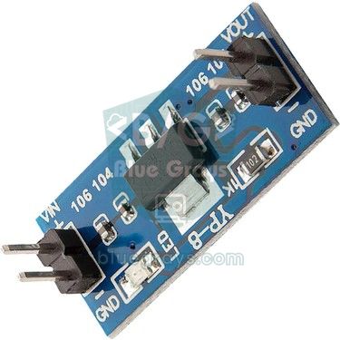
- Regulator dropout: the AMS1117 found on most boards needs a 1.0–1.3 V difference between its input and output. If the voltage on the 5V pin drops below roughly 4.3 V, the output can't hold 3.3 V.
- Connecting a battery directly: wiring a 3.7 V Li-ion cell to the 5V pin pulls the output below 3 V because of the regulator dropout; two AA cells quickly sag below the ESP32's minimum under load.
- The Arduino Uno's 3.3V pin: only about 50 mA is recommended from this pin; that's nowhere near enough for an ESP32 with Wi-Fi on.
- Loads on the same line: if servos, relays, buzzers, DC motors or a WS2812B strip run from the same 5 V as the ESP32, every movement drags the voltage down.
- Breadboards and jumper wires: loose contacts and thin jumpers add a bit of resistance at every connection; routing the power through a breadboard makes things worse.
- ESP32-CAM: when the camera, Wi-Fi and flash LED run at the same time, the current gets very high; this board likes 5 V and at least 2 A. See the ESP32-CAM guide for details.
Fix 1: improve the power supply and the cable
The first and most effective step is a stronger supply. Connect the board with a short, thick data cable you know is good, directly to a USB port on the back of your computer or to a 5 V adapter rated for at least 1 A. USB 2.0 ports are designed to deliver 500 mA and USB 3.0 ports 900 mA; the 500 mA Espressif recommends is right at the limit of a USB 2.0 port, so once cable losses are added the trouble starts. If swapping the cable alone fixes the error, the cable's resistance was most likely the culprit. You can work out how much voltage a cable loses with V = I × R in the Ohm's Law tool.
| Power setup | Brownout risk | Note |
|---|---|---|
| Short, thick cable and a rear USB port | Low | The easiest fix during development |
| Long, thin cable, front port or hub | High | Cable resistance pulls the voltage down at peak current |
| 5 V adapter rated for at least 1 A, into the 5V or VIN pin | Low | Recommended for permanent projects |
| Ready-made 3.3 V supply straight into the 3V3 pin | Depends on the supply | Must deliver at least 500 mA and never exceed 3.6 V |
| 3.7 V Li-ion cell through the AMS1117 | High | Below about 4 V on the cell, the output drops under 3 V |
| Li-ion cell with a low-dropout (LDO) 3.3 V regulator or a buck-boost | Low | Delivers a stable 3.3 V even as the cell discharges |
| Two AA cells straight into the 3V3 pin | Very high | Under load the voltage quickly falls below the ESP32's minimum |
Battery-powered projects need extra care. A Li-ion cell such as an 18650 gives 4.2 V when full and about 3.0 V when empty. That range suits neither a direct connection to the 3V3 pin (4.2 V exceeds the 3.6 V limit) nor the 5V pin with its AMS1117. The right solution is either to feed the cell through a 5 V boost module into the 5V pin, or to supply the 3V3 rail directly through a low-dropout regulator rated for at least 500 mA (for example an ME6211 or HT7833) plus a capacitor. You can estimate how long your project will run on a battery with the Battery life tool, and learn about the charging circuit in the TP4056 charging module guide.
Fix 2: add a capacitor between 3V3 and GND
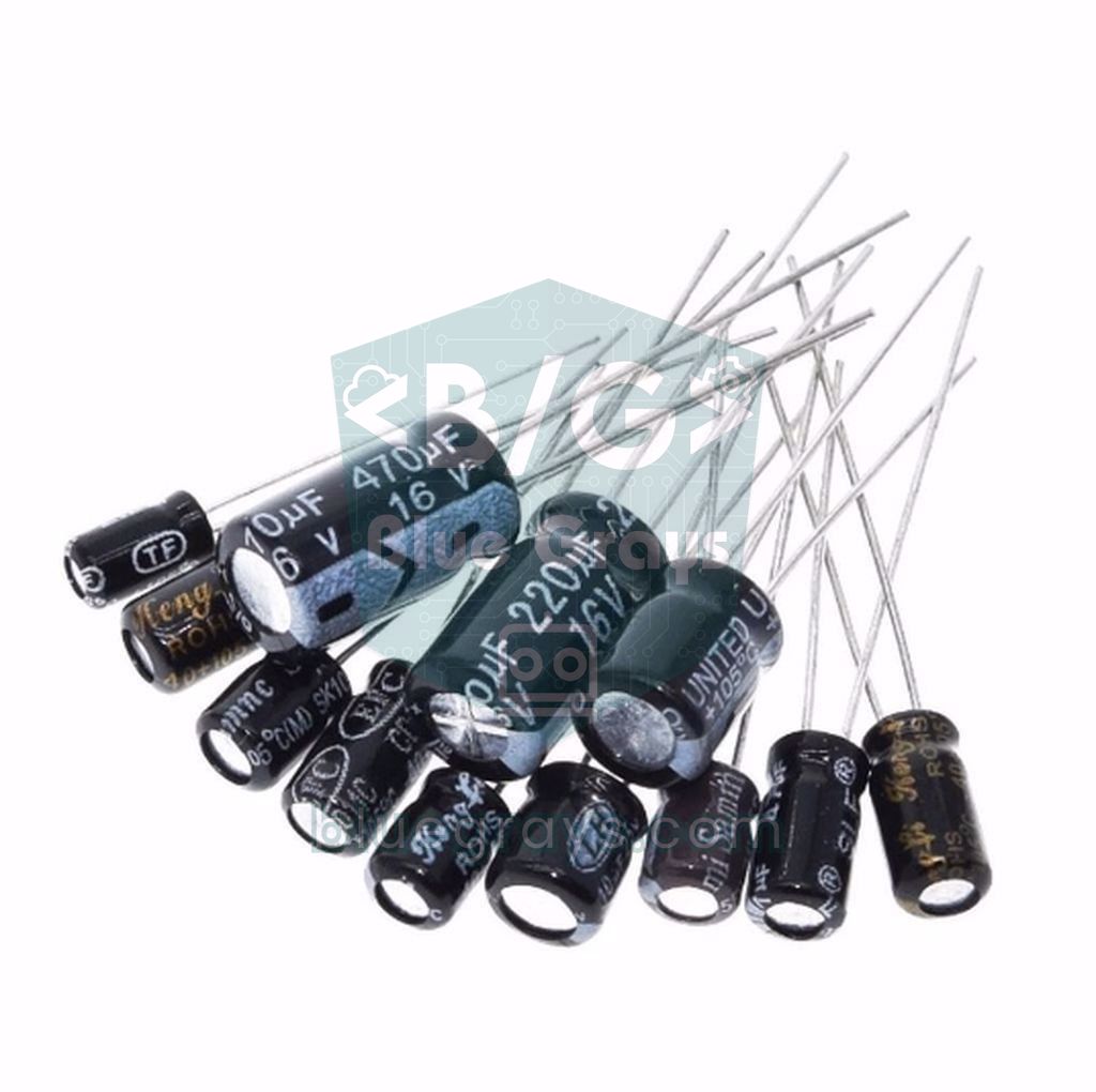
A capacitor acts like a small reservoir that supplies energy itself during a current peak until the regulator and cable catch up. Add a 100–470 µF electrolytic capacitor between the board's 3V3 and GND pins, as close to the board as possible, plus a 100 nF ceramic capacitor next to it. The electrolytic handles millisecond-long dips, the ceramic one handles very short, high-frequency ripple. You can roughly see the effect with ΔV = I × Δt / C: even if a 470 µF capacitor alone supplies an extra 200 mA for 200 µs, the voltage drops by only 0.085 V. The 104 marking on a ceramic capacitor means 100 nF; you can decode other markings with the Capacitor code tool.
Fix 3: power servos, motors and LED strips separately
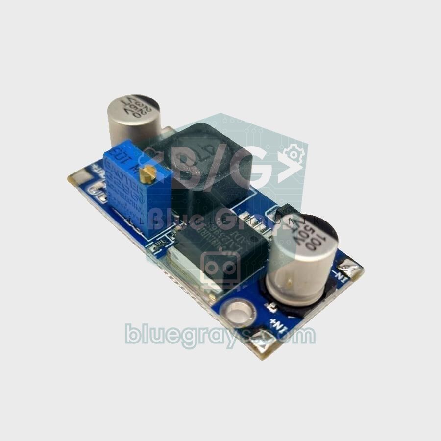
Even if the ESP32 itself is powered properly, loads on the same line can drag the voltage down. Even a small servo like the SG90 draws a few hundred mA as it starts to move; a WS2812B LED uses about 60 mA at full white, so a 30-LED strip can reach 1.8 A. Power these loads not from the ESP32's 5V or 3V3 pin but from a separate 5 V supply; for example, you can step a 12 V adapter down to 5 V with an LM2596 buck module. The most important rule is to connect the GND of both supplies together; without a common ground the signal line has no reference and the servo or strip behaves randomly. We cover this in detail in Arduino Keeps Resetting? and GND and common ground.
Is disabling the brownout detector a fix?
The most common "fix" online is to turn the detector off with a single line. The code below disables the detector by clearing the ESP32's brownout register, and the error message disappears. But the voltage dips continue; nobody warns you anymore, that's all. Use this code only for diagnosis: if the board runs fine with the detector off, you've confirmed that the problem is definitely the power supply. Then remove the line and fix the supply.
1#include "soc/soc.h"
2#include "soc/rtc_cntl_reg.h"
3
4void setup() {
5  // YALNIZ TEŞHİS İÇİN: brownout dedektörünü kapat / DIAGNOSIS ONLY: disable the brownout detector
6  WRITE_PERI_REG(RTC_CNTL_BROWN_OUT_REG, 0);
7
8  Serial.begin(115200);
9  Serial.println("Brownout dedektoru kapali / brownout detector disabled");
10}
11
12void loop() {
13}rst cause codes: the ESP32 tells you why it restarted
The rst: value the ROM prints on every boot shows how the previous run ended. On a normal boot the boot value is 0x13 (SPI_FAST_FLASH_BOOT), meaning the board starts its program from flash. The table below lists the codes you'll see most often. ROM codes aren't always enough on their own: ESP.restart() and a restart after a Guru Meditation both show up as 0xc, while a brownout appears as 0xc or 0x3 depending on the core version. To tell them apart, use the esp_reset_reason() sketch in the next section.
| rst code | Name | What it means |
|---|---|---|
| 0x1 | POWERON_RESET | Power was applied for the first time or the EN button was pressed |
| 0x3 | SW_RESET | Software reset the whole digital system; newer core versions also show it after a brownout |
| 0x5 | DEEPSLEEP_RESET | The board woke up from deep sleep (normal) |
| 0x7 / 0x8 | TG0WDT_SYS_RESET / TG1WDT_SYS_RESET | A timer group watchdog reset the system in hardware; interrupts stayed disabled for too long or even the panic handler couldn't run |
| 0x9 | RTCWDT_SYS_RESET | The RTC watchdog reset the digital core |
| 0xc | SW_CPU_RESET | Software restart: ESP.restart(), after a Guru Meditation, or after a brownout in the Arduino core |
| 0xf | RTCWDT_BROWN_OUT_RESET | Hardware brownout reset: unstable supply voltage |
| 0x10 | RTCWDT_RTC_RESET | The RTC watchdog reset the whole chip including the RTC; mostly seen on boards that hang during boot |
Diagnostic sketch: print the reset reason, memory and stack
Upload the code below as a separate sketch, or add its lines to the setup() and loop() of your problem project. Every time the board starts, it prints the reset reason as readable text, how many times it has booted and the memory status to the Serial Monitor. The counter marked with RTC_DATA_ATTR lives in RTC memory, so it survives software resets and deep sleep and is only cleared when power is fully removed. If the counter goes up every few seconds, you know right away that the board is in a reset loop.
1#include <esp_system.h>
2
3RTC_DATA_ATTR uint32_t bootCount = 0;   // yazılım resetinde korunur / survives software resets
4
5// Reset nedenini okunabilir yazıya çevir / turn the reset reason into readable text
6const char* reasonText(esp_reset_reason_t r) {
7  switch (r) {
8    case ESP_RST_POWERON:   return "POWERON: guc acilisi ya da EN / power-on or EN button";
9    case ESP_RST_SW:        return "SW: ESP.restart()";
10    case ESP_RST_PANIC:     return "PANIC: Guru Meditation";
11    case ESP_RST_INT_WDT:   return "INT_WDT: kesme watchdog'u / interrupt watchdog";
12    case ESP_RST_TASK_WDT:  return "TASK_WDT: gorev watchdog'u / task watchdog";
13    case ESP_RST_WDT:       return "WDT: diger watchdog / other watchdog";
14    case ESP_RST_DEEPSLEEP: return "DEEPSLEEP: derin uykudan uyanma / deep sleep wake-up";
15    case ESP_RST_BROWNOUT:  return "BROWNOUT: gerilim dusmesi / supply voltage dropped";
16    default:                return "UNKNOWN: bilinmiyor / unknown";
17  }
18}
19
20void setup() {
21  Serial.begin(115200);
22  delay(1000);                          // Seri Monitör'ün açılmasını bekle / wait for the Serial Monitor
23  bootCount++;
24  Serial.printf("Acilis sayisi / boot count: %u\n", (unsigned)bootCount);
25  Serial.printf("Reset nedeni / reset reason: %s\n", reasonText(esp_reset_reason()));
26}
27
28void loop() {
29  // Bellek durumu / memory status
30  Serial.printf("Bos heap / free heap: %u B, en dusuk / minimum: %u B, en buyuk blok / largest block: %u B\n",
31                (unsigned)ESP.getFreeHeap(), (unsigned)ESP.getMinFreeHeap(), (unsigned)ESP.getMaxAllocHeap());
32  // loopTask yığınında hiç kullanılmamış en küçük alan / smallest unused space on the loopTask stack
33  Serial.printf("loopTask bos yigin / free stack: %u B\n", (unsigned)uxTaskGetStackHighWaterMark(NULL));
34  delay(5000);
35}
The values printed in the loop reveal silent problems too. If the free heap drops a little on every pass, your program has a memory leak and the board will crash sooner or later. If the largest block is much smaller than the free heap, memory is fragmented; this usually comes from String objects that keep growing and shrinking inside the loop. If loopTask's free stack falls below a few hundred bytes, a stack overflow is just around the corner. If the reset reason is BROWNOUT, focus on the power sections; if it's PANIC, TASK_WDT or INT_WDT, focus on the software sections below.
What is a Guru Meditation Error? Read the crash output line by line
A Guru Meditation Error is the crash report the panic handler prints when the ESP32's CPU hits an error it can't recover from; the name comes from the error screen of old Amiga computers. The report looks scary at first, but only a few lines matter. Core 1 tells you which core the error happened on: in Arduino, setup() and loop() run on core 1, while the Wi-Fi stack runs on core 0. The name in parentheses is the exception type. When the report ends, the board prints "Rebooting..." and restarts; you'll see rst:0xc on the boot line.
| Line | Meaning |
|---|---|
| Guru Meditation Error: Core 1 panic'ed (LoadProhibited). Exception was unhandled. | Code on core 1 tried to read from an invalid address and the error wasn't handled |
| PC : 0x400d1a2c | Address of the instruction that crashed; if it starts with 0x400d, your code or a library was running from flash |
| EXCCAUSE: 0x0000001c | Exception code; 0x1c, i.e. 28, means LoadProhibited |
| EXCVADDR: 0x00000000 | The address that was accessed; 0 or a very small number points to a null pointer |
| Backtrace: 0x400d1a29:0x3ffb2270 0x400d0f6e:0x3ffb2290 ... | Call chain; each pair is PC:SP and can be turned into a line of code with the decoder |
| ELF file SHA256: ... | Fingerprint of the crashed program; the decoder needs exactly the same build |
| Rebooting... | The panic handler restarts the chip in software |
LoadProhibited, StoreProhibited and other exception types
| Exception | EXCCAUSE | What happened? | Common cause |
|---|---|---|---|
| LoadProhibited | 28 (0x1c) | Read from an invalid address | Null or uninitialised pointer, deleted object |
| StoreProhibited | 29 (0x1d) | Write to an invalid address | Writing through a null pointer, buffer overrunning an array |
| InstrFetchProhibited | 20 (0x14) | Fetching an instruction from an invalid address | Unassigned function pointer or callback |
| IllegalInstruction | 0 (0x0) | Invalid instruction | Corrupted stack, missing return in a function that must return a value |
| LoadStoreAlignment | 9 (0x9) | Unaligned memory access | Casting a byte array to a type like uint32_t* |
| IntegerDivideByZero | 6 (0x6) | Integer division by zero | Dividing by a counter that can be zero |
| Unhandled debug exception | - | Debug exception | Stack canary watchpoint triggered: stack overflow |
| Interrupt wdt timeout on CPU0/CPU1 | - | Interrupt watchdog expired | Long ISR, Serial or delay inside an ISR |
| Cache disabled but cached memory region accessed | - | Code in flash accessed while flash was busy | Interrupt handler without IRAM_ATTR |
The most common of these errors is using a null pointer. NULL is address 0, and on the ESP32 there's no readable memory around address 0, so reading from where an empty pointer points gives LoadProhibited and writing there gives StoreProhibited. In this case EXCVADDR is a perfect clue: 0x00000000 points to the pointer itself, while small values like 0x00000004 or 0x00000010 point to a field inside an empty pointer (NULL plus the field's offset). In Arduino projects the most common cause is a function returning NULL to mean "not found" and that value being used without a check. In the example below, strstr() returns NULL if it doesn't find the text; without a check the board crashes with EXCVADDR 0x00000005.
1const char* response = "temp=23.5;hum=40";   // sunucudan gelen yanıt / reply from a server
2
3void setup() {
4  Serial.begin(115200);
5  delay(500);
6
7  // YANLIŞ: "pres=" yoksa strstr NULL döner ve kart çöker (EXCVADDR 0x00000005)
8  // WRONG: if "pres=" is missing strstr returns NULL and the board crashes (EXCVADDR 0x00000005)
9  // float pressure = atof(strstr(response, "pres=") + 5);
10
11  // DOĞRU: işaretçiyi kullanmadan önce NULL kontrolü yap / RIGHT: check for NULL before using the pointer
12  const char* found = strstr(response, "pres=");
13  if (found != nullptr) {
14    float pressure = atof(found + 5);
15    Serial.println(pressure);
16  } else {
17    Serial.println("pres alani bulunamadi / pres field not found");
18  }
19}
20
21void loop() {
22}Stack overflow: the "Stack canary watchpoint triggered" error
On the ESP32 every task has a fixed-size stack, where local variables, function calls and return addresses are stored. In Arduino, the loopTask that runs setup() and loop() has a stack of 8192 bytes. Declaring a 10,000-byte local array inside loop(), a function that calls itself (recursion) or a library function with lots of local variables will exceed this limit. At the end of the stack there's a guard (canary) area; when the stack reaches it, the board prints Guru Meditation Error: Core 1 panic'ed (Unhandled debug exception) and right below it Debug exception reason: Stack canary watchpoint triggered (loopTask). The name in parentheses is the task whose stack overflowed. The same problem sometimes shows up as ***ERROR*** A stack overflow in task loopTask has been detected. Here's how to fix it:
- Move large arrays off the stack: declare the array globally or add static in front of it; then it lives in permanent RAM instead of on the stack.
- Enlarge the loopTask stack: put SET_LOOP_TASK_STACK_SIZE(16 * 1024); at the top of your sketch to raise the loop() stack to 16 KB.
- Give your own tasks enough room: on the ESP32, the stack size passed to xTaskCreate and xTaskCreatePinnedToCore is in bytes, not words as in FreeRTOS on other platforms. 1024 bytes is too little even for a task that uses Serial.printf; start with 4096.
- Measure: uxTaskGetStackHighWaterMark(NULL) returns, in bytes, the smallest amount of stack the task has never used so far; if it drops below a few hundred bytes, enlarge the stack.
- Avoid recursion: turn self-calling functions into loops or limit their depth.
Task watchdog: the "task_wdt: Task watchdog got triggered" error
A watchdog is a timer that notices a stuck program and rescues the board. The ESP32's Task Watchdog (Task WDT) expects the tasks registered with it to signal "I'm alive" at regular intervals. In the Arduino core it watches the idle (IDLE) task of core 0 by default, with a timeout of 5 seconds. If a task running on core 0 doesn't release the CPU for 5 seconds, the IDLE task can't run and the Serial Monitor shows a message starting with E (10257) task_wdt: Task watchdog got triggered. It's followed by the list of tasks that didn't reset the watchdog in time (usually - IDLE (CPU 0)) and, under Tasks currently running:, the tasks running at that moment. In the Arduino core this triggers a panic with the line task_wdt: Aborting. and the board restarts.
The most common causes are: a loop pinned to core 0 with xTaskCreatePinnedToCore that never calls vTaskDelay(), a while loop waiting for a sensor reply without a timeout, or delay() and long operations inside the callbacks of libraries such as AsyncWebServer. In the last case you'll see the async_tcp task in the list instead of IDLE. The fix is to split long jobs into small pieces and add short waits such as vTaskDelay(1) to your loops. The loop() function itself isn't watched by default; if you want, call enableLoopWDT() in setup() so the board also restarts when loop() hangs for more than 5 seconds. Turning the watchdog off with disableCore0WDT() hides the error but doesn't fix the stuck code. For more on tasks and cores, see ESP32 FreeRTOS and dual core. The code below shows both a proper task structure and the precautions against stack overflow:
1SET_LOOP_TASK_STACK_SIZE(16 * 1024);   // loop() yığını 8 KB yerine 16 KB / loop() stack 16 KB instead of 8 KB
2
3volatile uint32_t sampleCount = 0;
4
5// 0. çekirdekte çalışan görev / task running on core 0
6void sensorTask(void* parameter) {
7  for (;;) {
8    sampleCount = sampleCount + 1;       // sensörünü burada oku / read your sensor here
9    vTaskDelay(pdMS_TO_TICKS(10));       // IDLE görevine sıra ver, task_wdt tetiklenmez / let IDLE run, no task_wdt
10  }
11}
12
13void setup() {
14  Serial.begin(115200);
15  // Yığın boyutu bayt cinsindendir: 4096 bayt / stack size is in bytes: 4096 bytes
16  xTaskCreatePinnedToCore(sensorTask, "sensorTask", 4096, NULL, 1, NULL, 0);
17}
18
19void loop() {
20  static uint8_t buffer[10000];          // static: yığında değil kalıcı RAM'de / static: in RAM, not on the stack
21  memset(buffer, 0, sizeof(buffer));
22
23  Serial.printf("Ornek / samples: %u, loopTask bos yigin / free stack: %u B\n",
24                (unsigned)sampleCount, (unsigned)uxTaskGetStackHighWaterMark(NULL));
25  delay(1000);
26}
Interrupt wdt timeout and IRAM_ATTR: crashes in interrupts
The Interrupt Watchdog (Interrupt WDT) is much less patient: if an interrupt handler (ISR) or a section of code with interrupts disabled takes longer than 300 ms, the board crashes with Guru Meditation Error: Core 1 panic'ed (Interrupt wdt timeout on CPU1). Using Serial.print, delay(), I2C or Wi-Fi inside an ISR is the most common cause. Flash memory is another trap: while Preferences, EEPROM or LittleFS write to flash, the flash cache is disabled for a moment. If an interrupt arrives during that time and its handler lives in flash, the board reports Cache disabled but cached memory region accessed. The fix is to mark ISRs with IRAM_ATTR so they live in RAM and to only set a flag inside them; loop() does the real work. Variables shared between an ISR and loop() must be volatile.
1const int BUTTON_PIN = 27;              // buton GPIO 27 ile GND arasında / button between GPIO 27 and GND
2volatile bool buttonPressed = false;    // ISR ile loop arasında paylaşılan bayrak / flag shared by the ISR and loop
3uint32_t pressCount = 0;
4
5void IRAM_ATTR onButton() {             // IRAM_ATTR: fonksiyon flaşta değil RAM'de durur / the function lives in RAM, not flash
6  buttonPressed = true;                 // yalnızca bayrak kaldır, Serial yok / only set a flag, no Serial
7}
8
9void setup() {
10  Serial.begin(115200);
11  pinMode(BUTTON_PIN, INPUT_PULLUP);
12  attachInterrupt(digitalPinToInterrupt(BUTTON_PIN), onButton, FALLING);
13}
14
15void loop() {
16  if (buttonPressed) {
17    buttonPressed = false;
18    pressCount++;
19    Serial.printf("Butona basildi / button pressed: %u\n", (unsigned)pressCount);   // yavaş iş burada / slow work here
20  }
21}
Turning the Backtrace into a line of code with the ESP Exception Decoder
The addresses in the Backtrace line don't tell you anything on their own; the tool that turns them into the file, function and line number in your source code is called the ESP Exception Decoder. In the old Arduino IDE 1.8 it was a plugin added to the Tools menu. In Arduino IDE 2 you use a community-made extension with the same name:
- Download the .vsix file from the Releases section of the dankeboy36/esp-exception-decoder project on GitHub. For Arduino IDE 2 pick a 1.x release; the newer 2.x releases are made for VS Code.
- Close the Arduino IDE and copy the file into %UserProfile%\.arduinoIDE\plugins on Windows or ~/.arduinoIDE/plugins on macOS and Linux; create the folder if it doesn't exist.
- Open the IDE, open the crashing sketch, compile it with Verify and upload it to the board.
- Open the Serial Monitor and wait for the crash to happen again.
- Open the command palette with Ctrl+Shift+P (Cmd+Shift+P on macOS) and run ESP Exception Decoder: Show Decoder Terminal.
- Copy the Guru Meditation block from the Serial Monitor, including the Backtrace line, and paste it into the terminal that opens; the tool shows every address with its file name, function and line number.
If you can't install the extension, you can do the same job by hand. The Sketch > Export Compiled Binary menu leaves a file with the .elf extension in the build folder inside your sketch folder. The command xtensa-esp32-elf-addr2line -pfiaC -e sketch.ino.elf 0x400d1a29 0x400d0f6e from the ESP32 toolchain turns these addresses into function names and line numbers. If you use PlatformIO, just add the line monitor_filters = esp32_exception_decoder to platformio.ini; crash output is then decoded automatically in the serial monitor.
Strapping pins: how GPIO0, GPIO2, GPIO12 and GPIO15 can break the boot
When the ESP32 starts, it looks at the level of certain pins to decide how to boot. These are called strapping pins, and only their level at the moment of reset matters; once boot is finished they can be used as normal GPIOs. The problem is when a sensor, button or module you connect to one of them pulls the pin to the wrong level at boot. Then the board doesn't start its program at all, enters programming mode or can't read the flash; from the outside this also looks like "the ESP32 won't boot" or "it keeps resetting". You can see your board's full pin map in the Pinout tool.
| Pin | Internal resistor | Role at boot | What happens at the wrong level? |
|---|---|---|---|
| GPIO0 | Pull-up | LOW selects programming (download) mode, HIGH normal boot | boot:0x3 (DOWNLOAD_BOOT) and waiting for download; the program doesn't run |
| GPIO2 | Pull-down | Must be LOW or floating to enter programming mode; doesn't matter for normal boot | A circuit pulling it HIGH blocks uploads |
| GPIO12 (MTDI) | Pull-down | Selects the flash supply voltage: LOW 3.3 V, HIGH 1.8 V | If HIGH, a 3.3 V flash isn't powered properly; the board won't boot or enters a reset loop |
| GPIO15 (MTDO) | Pull-up | LOW silences the ROM boot messages | Boot lines don't appear in the Serial Monitor, making diagnosis harder |
| GPIO5 | Pull-up | Sets SDIO timing | Rarely causes problems on development boards |
Newer boards have different strapping pins: on the ESP32-S3 it's GPIO0, GPIO3, GPIO45 and GPIO46, and on the ESP32-C3 GPIO2, GPIO8 and GPIO9 affect the boot. The ESP32-S3 uses the same Xtensa exception names as the classic ESP32. On the RISC-V based ESP32-C3, however, you'll see Load access fault instead of LoadProhibited and Store access fault instead of StoreProhibited, and the MTVAL register takes over the role of EXCVADDR. The brownout message is the same on every model.
ESP32 and Raspberry Pi Pico in MicroPython
If you program the ESP32 in MicroPython, brownouts happen in exactly the same way, because the problem is in the hardware, not the software. Errors in Python code, on the other hand, appear as a readable Traceback instead of a Guru Meditation, and the board rarely crashes. You can read the reset reason with machine.reset_cause(), but watch out: the ESP32 port of MicroPython doesn't return brownout as a separate value, it reports it as PWRON_RESET together with power-on. If the board keeps starting with PWRON_RESET while you haven't touched it, suspect the power supply again. The code below is for the ESP32; on the Raspberry Pi Pico the machine module knows fewer reset types. On the Pico, the buck-boost regulator on the VSYS input works with anything from 1.8 to 5.5 V, so brownout problems are much rarer; to get to know the board, see What Is the Raspberry Pi Pico?
1import machine, gc, time
2
3# Reset nedenleri (ESP32 için) / reset causes (for ESP32)
4causes = {
5    machine.PWRON_RESET: "PWRON: guc acilisi ya da brownout / power-on or brownout",
6    machine.HARD_RESET: "HARD: cokme ya da machine.reset() / crash or machine.reset()",
7    machine.WDT_RESET: "WDT: watchdog",
8    machine.DEEPSLEEP_RESET: "DEEPSLEEP: derin uykudan uyanma / deep sleep wake-up",
9    machine.SOFT_RESET: "SOFT: Ctrl+D ile yazilim reseti / soft reset with Ctrl+D",
10}
11print("Reset nedeni / reset cause:", causes.get(machine.reset_cause(), "bilinmiyor / unknown"))
12
13while True:
14    gc.collect()                                     # çöp toplayıcıyı çalıştır / run the garbage collector
15    print("Bos RAM / free RAM:", gc.mem_free(), "bayt / bytes")
16    time.sleep(5)
Common mistakes and fixes
| Symptom | Likely cause | Fix |
|---|---|---|
| Brownout detector was triggered when Wi-Fi starts | Cable, port or regulator can't keep up with peak current | Short thick cable, 1 A adapter, 470 µF + 100 nF between 3V3 and GND |
| Reset when a servo turns or a relay switches | The load shares the ESP32's supply line | Power the load from a separate 5 V supply and join the GNDs |
| Resets start once the battery is a bit drained | AMS1117 dropout | Use an LDO or a buck-boost converter |
| Guru Meditation, EXCVADDR 0x00000000 | Null pointer | Check the pointer before using it |
| Stack canary watchpoint triggered (loopTask) | The loop() stack is full | Make large arrays static or use SET_LOOP_TASK_STACK_SIZE |
| task_wdt: - IDLE (CPU 0) | Loop without waits on core 0 | Add vTaskDelay to the loop |
| Interrupt wdt timeout on CPU1 | ISR takes too long | Only set a flag in the ISR, use IRAM_ATTR |
| Board silent, boot:0x3 and waiting for download | GPIO0 LOW at boot | Remove the circuit on GPIO0, press EN |
| Board doesn't boot at all, flash read error | GPIO12 HIGH at boot | Move the pull-up or the module on GPIO12 to another pin |
| Failed to connect to ESP32 while uploading | GPIO2 HIGH or the board can't enter programming mode | Free GPIO2, hold BOOT as the upload starts |
Your board runs stable: what's next?
- Battery-friendly device: with ESP32 deep sleep, put the board to sleep between measurements and draw current in the microamp range.
- Wireless updates: upload code without a USB cable using ESP32 OTA.
- Real-time dashboard: watch sensor data live in the browser with ESP32 WebSocket.
- Send notifications: with an ESP32 Telegram bot, get the reset reason on your phone every time the board restarts.
- Light show: drive a WS2812B NeoPixel strip safely with a separate supply.
Most ESP32 reboot problems are either a power issue or a few lines of buggy code; once you read the message correctly, both are fixed quickly. To refresh the basics of the board, take a look at What Is the ESP32? In the BlueGrays app you'll find ESP32 projects with LEDs, servos, NeoPixel strips, Wi-Fi connections, a web server, OTA updates and deep sleep, each with a step-by-step circuit diagram and code, so you can try the power and diagnostic techniques you learned here in real projects.
Frequently asked questions
How do I fix ESP32 brownout detector was triggered?
This error means the ESP32's supply voltage briefly dropped below about 2.43 V. First use a short, thick USB cable with a 5 V supply rated for at least 1 A, then add a 100–470 µF electrolytic and a 100 nF ceramic capacitor between 3V3 and GND. Power loads such as servos, relays and LED strips from a separate supply and connect the GNDs together.
Why does my ESP32 keep rebooting?
The most common causes are an insufficient power supply (brownout), software crashes (Guru Meditation), watchdog timeouts and strapping pins stuck at the wrong level at boot. Open the Serial Monitor at 115200 baud and press EN; the last message before the reset and the rst code at boot show the cause. The esp_reset_reason() function also lets you read it from your code.
What does Guru Meditation Error LoadProhibited mean?
It means code on the ESP32 tried to read from an invalid memory address. If EXCVADDR is 0 or a very small number, a null pointer was almost certainly used. Paste the Backtrace line into the ESP Exception Decoder to find the file and line where the error happened.
Can I disable the ESP32 brownout detector?
Yes, the line WRITE_PERI_REG(RTC_CNTL_BROWN_OUT_REG, 0) disables it, but that only silences the warning. Since the voltage dips continue, data in flash can get corrupted and the board can crash with other errors. Use this only briefly to confirm that the problem comes from the power supply.
How do I fix ESP32 Task watchdog got triggered?
This message means a watched task didn't release the CPU for 5 seconds; in Arduino the list usually shows the IDLE task of core 0. Add vTaskDelay() to the loops in your own tasks, use timeouts when waiting for sensors, and avoid delay() or long operations in web server callbacks. Turning the watchdog off hides the error but doesn't fix the cause.
What power supply does an ESP32 need?
Espressif recommends a power supply that can deliver at least 500 mA for the ESP32; in practice a 5 V, 1 A adapter leaves a safe margin. If you use an ESP32-CAM or add loads such as servos or LED strips, choose a supply rated for 2 A or more and power those loads from a separate line if possible.
Projects to build after reading this
See all projects
LED Blink with ESP32
Teaches basic GPIO output usage with ESP32. We achieve a blinking effect by turning an LED on and off from a digital pin. ESP32 version of the classic blink project on Arduino UNO; the basic blink commands in the Arduino environment are the same, but the ESP32's pin layout and 3.3 V GPIO levels differ from those of the Arduino UNO.

ESP32 Wi-Fi STA Connection (with LCD Screen)
In this project, we connect the ESP32 to the home Wi-Fi network in Station (STA) mode in a secure, fault-tolerant manner. We store the SSID and password in a separate secrets.h file to prevent leaking to Git, set up an auto-reconnect mechanism, and display the RSSI signal level and IP address on an I2C LCD screen. The internal LED works as a status indicator. It is a production-grade connection manager.

ESP32 Servo Motor (Potentiometer Control)
In this project, we control an SG90 servo motor using a potentiometer. We adjust the servo angle by mapping the analog value read from the potentiometer to the 0–180-degree range. The ESP32Servo library generates servo signals on suitable output-capable GPIO pins of the ESP32; this project uses GPIO 18. This is a fundamental control method for robotic arms, camera gimbals, and automatic door mechanisms.

ESP32 WS2812B NeoPixel Strip Control
WS2812B (NeoPixel) addressable LEDs are smart RGB LEDs that can be controlled in a daisy-chain configuration via a single data pin. In this project, we will control an 8-LED WS2812B strip using the Adafruit_NeoPixel library to create a smooth rainbow animation. While the ESP32’s 3.3V logic level works seamlessly with most WS2812B components, we’ll demonstrate a solution using a 470Ω series resistor and a 1000µF capacitor in case of instability. The animation is achieved by shifting the hue value

ESP32 Asynchronous Web Server (with IP Display on LCD)
In this project, we’re turning the ESP32 into an asynchronous web server that you can control from your phone or computer on the same Wi-Fi network. Thanks to the ESPAsyncWebServer library, the server can process multiple requests simultaneously (unlike the classic WebServer.h, which blocks on a single request). You’ll be able to open the ESP32’s IP address in a browser and click the ON/OFF buttons (the /on and /off routes) to turn the LED connected to GPIO 5 on and off.

ESP32 Deep Sleep — Battery Saving (OLED + RTC RAM Counter)
The ESP32's Deep Sleep mode reduces current consumption to ~10 µA by shutting down the CPU and most peripherals, making it critical for battery-powered IoT devices. In this project, we use three different wake-up sources: a timer (15 seconds), an external pin (EXT0 — button GPIO 33), and touch (T0/GPIO 4). Variables marked with RTC_DATA_ATTR are preserved during deep sleep—the boot counter, timer wake counter, and button wake counter are continuously tracked. On each wake-up, the SSD1306 OLED

ESP32 OTA Update — Wireless Firmware Installation (With LCD Screen)
In this project, you’ll learn how to upload new firmware to the ESP32 over Wi-Fi without a USB cable. Using the ArduinoOTA library, the ESP32 becomes visible on the network and is automatically listed as bluegrays-ota in the "Network port" tab of the Arduino IDE. The initial upload is done via USB, and all subsequent updates are wireless—a critical feature for field devices. The I2C LCD screen displays the Wi-Fi status, IP address, hostname, OTA upload percentage, and error messages in both
ESP32 Motion Alarm System (PIR + Buzzer + LED + Telegram)
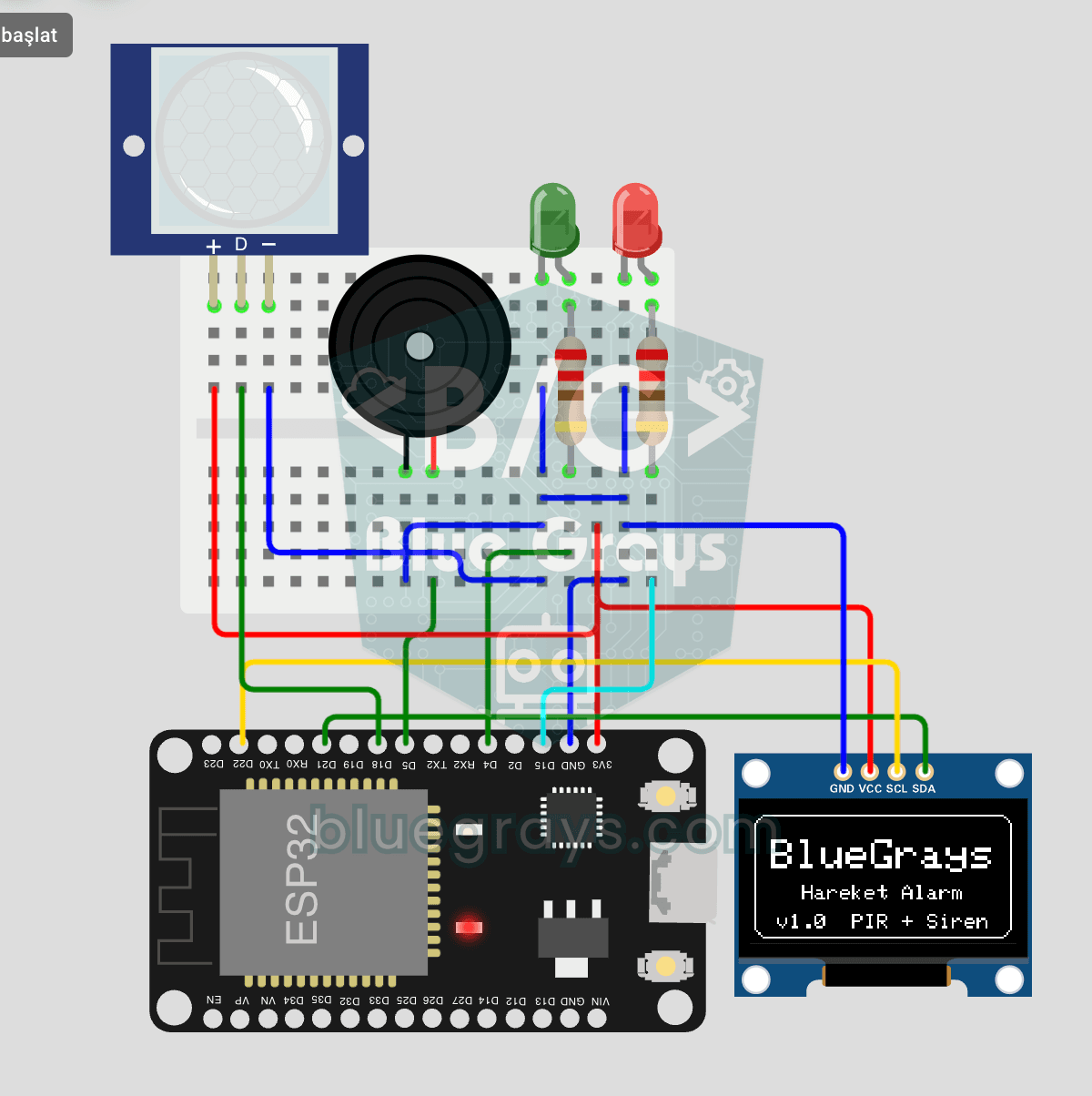
A smart security alarm system that activates the buzzer and LED when the PIR sensor detects motion, while simultaneously sending an instant notification to the owner via Telegram. It includes a 30-second cooldown to limit the frequency of repeated alarms; this mechanism does not validate PIR detections or eliminate false triggers. Suitable for home security, garage monitoring, warehouses, or workrooms. With ESP32-CAM, photo notifications can be added; with the classic ESP32 DevKit V1, text notif