
Raspberry Pi Pico PIO and Dual Core: _thread, setup1, WS2812B
Raspberry Pi Pico PIO guide: state machines, a square wave and a WS2812B example, both cores with MicroPython _thread and Arduino setup1/loop1, Pico 2 changes.
The Raspberry Pi Pico PIO block and its two cores are the two features that set this little board apart from most microcontrollers in its price range. The RP2040 chip at the heart of the Pico has two separate processor cores and 8 PIO state machines. Thanks to the cores you can read sensors on one side while a display or LED animation keeps running smoothly on the other. PIO, on the other hand, is a set of tiny timing engines that run independently of the processor: they produce the nanosecond-accurate signal WS2812B LEDs need, an extra UART or a square wave without putting any load on the CPU.
In this guide you'll first run both cores with the _thread module in MicroPython, then with setup1() and loop1() in the Arduino IDE. After that you'll learn how PIO works, how many state machines there are and which instructions they understand, and you'll write two real programs: a square wave generator that plays notes on a buzzer and a WS2812B rainbow. The last sections look at what the Pico 2 (RP2350) changes and when you actually need these features. If you're new to the Pico, I recommend reading What Is the Raspberry Pi Pico? and What Is MicroPython? first.
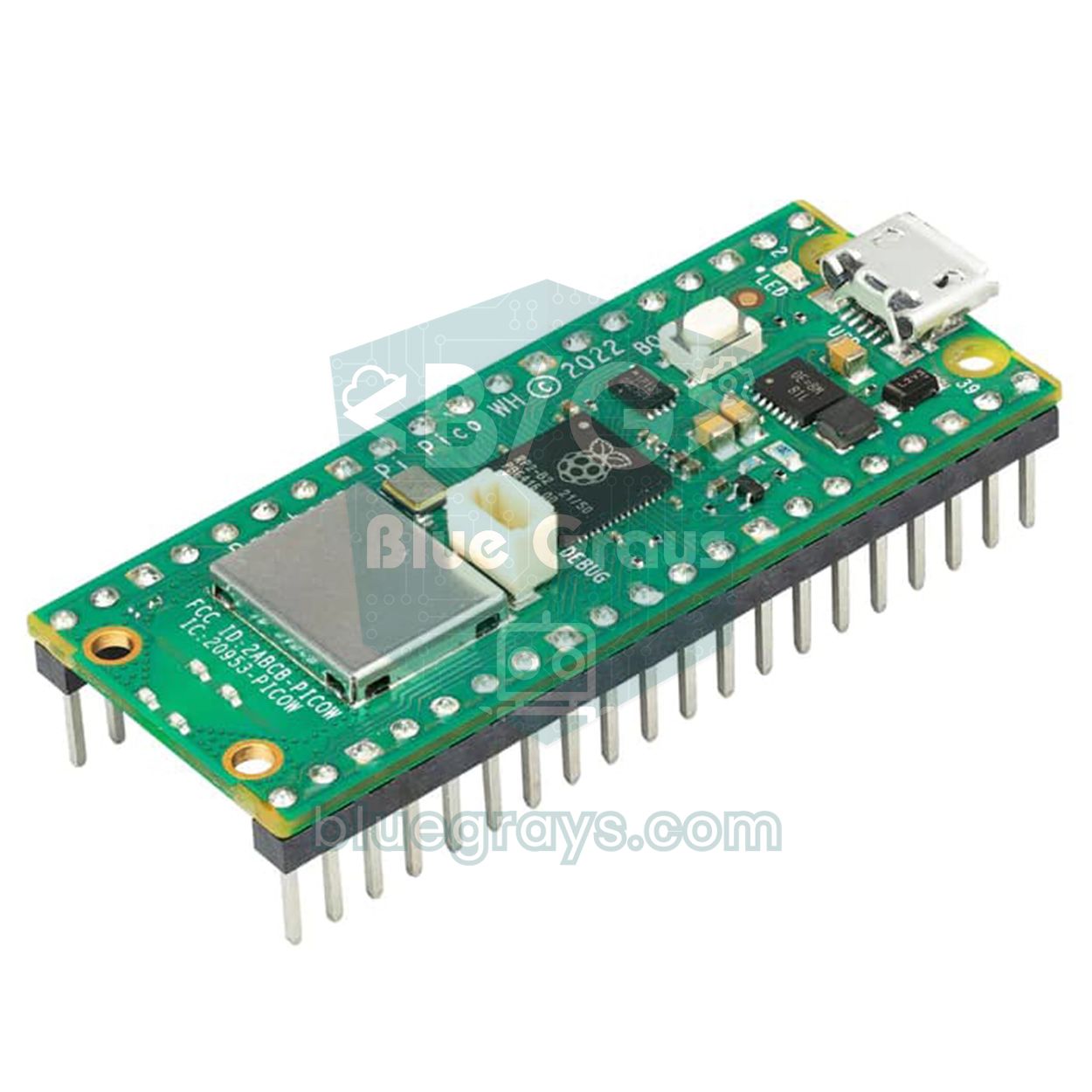
What are the Raspberry Pi Pico's two cores and PIO?
The RP2040 has two identical Cortex-M0+ processors called core 0 and core 1. When your program starts, only core 0 runs; core 1 sleeps until you start it. Both cores share the same 264 KB of RAM and the same pins, so moving data between them is easy, but they must not write the same variable at the same moment. For that the chip has a small two-way hardware queue (FIFO, 8 words in each direction) and 32 hardware locks (spinlocks). PIO is a completely separate world: each of the two PIO blocks has 4 state machines, a shared 32-instruction program memory and direct access to the pins. Once a state machine is started, it executes its own program cycle by cycle even while the processor is busy with something else.
| Resource | RP2040 (Pico, Pico W) | What is it for? |
|---|---|---|
| Processor core | 2 x Cortex-M0+, 133 MHz (up to 200 MHz in current documents) | Running two separate programs truly at the same time |
| Inter-core FIFO | 8 x 32-bit in each direction | Sending numbers and commands between the cores |
| Hardware lock (spinlock) | 32 | Taking turns on shared data |
| PIO block | 2 (PIO0, PIO1) | Moving timing-critical pin work off the processor |
| State machine | 4 per block, 8 in total | Each one runs its own PIO program |
| PIO program memory | 32 instructions per block | Shared by the 4 state machines in that block |
| PIO FIFO | TX 4 + RX 4 words per machine (8 when joined) | Data between the processor and a state machine |
The second core in MicroPython: the _thread module
In MicroPython the way to use core 1 is the call _thread.start_new_thread(function, args). On the Pico this starts the function on the second core, while your main program carries on on core 0. Only one extra thread can run at a time, because there is no third core. In the example below, core 0 reads a potentiometer on GP26 and prints the result, while core 1 blinks the onboard LED at the speed set by the potentiometer. The sleep_ms() wait on core 1 doesn't affect core 0 at all; on a single core you'd need a timer or asyncio for that.
1# Pico - iki çekirdek (MicroPython _thread) / two cores (MicroPython _thread)
2import _thread
3import time
4from machine import Pin, ADC
5
6led = Pin("LED", Pin.OUT)          # Pico ve Pico W dahili LED / onboard LED on Pico and Pico W
7pot = ADC(26)                      # GP26 = ADC0, potansiyometre / potentiometer
8
9lock = _thread.allocate_lock()     # ortak veri kilidi / shared data lock
10blink_ms = 500                     # çekirdek 0 yazar, çekirdek 1 okur / core 0 writes, core 1 reads
11running = True                     # durdurma bayrağı / stop flag
12
13
14def core1_task():
15    # Çekirdek 1: LED'i kendi hızında yakıp söndürür / Core 1: blinks the LED at its own pace
16    while running:
17        with lock:
18            period = blink_ms
19        led.toggle()
20        time.sleep_ms(period)
21    led.off()
22
23
24_thread.start_new_thread(core1_task, ())   # ikinci çekirdekte başlat / start on the second core
25
26try:
27    while True:
28        # Çekirdek 0: sensörü okur ve hızı ayarlar / Core 0: reads the sensor and sets the speed
29        raw = pot.read_u16()                     # 0-65535
30        with lock:
31            blink_ms = 50 + raw * 950 // 65535   # 50-1000 ms
32        print("ham / raw:", raw, "ms:", blink_ms)
33        time.sleep_ms(200)
34except KeyboardInterrupt:
35    running = False                              # çekirdek 1'e dur de / tell core 1 to stop
36 time.sleep_ms(1100)- The lock made with allocate_lock() makes sure that inside a with lock: block only one core touches the shared variable.
- The running flag tells core 1 to leave its loop when you stop the program with Ctrl+C; otherwise the LED keeps blinking.
- Writing Pin("LED") finds the onboard LED on both the Pico and the Pico W; on the Pico W the LED is wired to the wireless chip, so Pin(25) doesn't work.
- A good split is to keep long calculations, display drawing or precise timing on core 1, and Wi-Fi, menus and user interaction on core 0.
Two cores in the Arduino IDE: setup1() and loop1()
The most widely used Pico package for the Arduino IDE is the Raspberry Pi Pico/RP2040/RP2350 core by Earle Philhower (arduino-pico). Using both cores with it is surprisingly easy: the familiar setup() and loop() run on core 0; if you add setup1() and loop1() to the sketch, core 1 starts automatically and runs those two functions. Data is sent between the cores with the rp2040.fifo object. Arduino's official "Arduino Mbed OS RP2040" package does not support setup1(), so make sure you pick the right package in the Boards Manager.
1// Raspberry Pi Pico - iki çekirdek (Arduino-Pico çekirdeği) / two cores (Arduino-Pico core)
2const int POT_PIN = 26;        // GP26 = ADC0, potansiyometre / potentiometer
3
4// ---- Çekirdek 0 / Core 0 ----
5void setup() {
6  Serial.begin(115200);
7}
8
9void loop() {
10  int raw = analogRead(POT_PIN);   // 0-1023 (varsayılan 10 bit / default 10-bit)
11  rp2040.fifo.push_nb(raw);        // FIFO doluysa bekleme, değeri atla / skip the value if the FIFO is full
12  Serial.print("pot: ");
13  Serial.println(raw);
14  delay(100);
15}
16
17// ---- Çekirdek 1 / Core 1 ----
18void setup1() {
19  pinMode(LED_BUILTIN, OUTPUT);
20}
21
22void loop1() {
23  static uint32_t periodMs = 500;
24  uint32_t value;
25  while (rp2040.fifo.pop_nb(&value)) {           // FIFO'yu boşalt, sonuncuyu kullan / drain the FIFO, keep the last one
26    periodMs = map(value, 0, 1023, 50, 1000);
27  }
28  digitalWrite(LED_BUILTIN, HIGH);
29  delay(periodMs);                               // yalnız çekirdek 1'i bekletir / only blocks core 1
30  digitalWrite(LED_BUILTIN, LOW);
31  delay(periodMs);
32}| Function | What it does |
|---|---|
| rp2040.fifo.push(x) | Sends a 32-bit value to the other core; waits for space if the queue is full |
| rp2040.fifo.push_nb(x) | Tries to send without waiting; returns false if the queue is full |
| rp2040.fifo.pop() | Reads a value from the other core; waits if the queue is empty |
| rp2040.fifo.pop_nb(&x) | Writes a value into x and returns true if there is one, otherwise returns false at once |
| rp2040.fifo.available() | Returns how many values are waiting to be read |
| rp2040.idleOtherCore() / resumeOtherCore() | Briefly pauses and resumes the other core (for example while writing to flash) |
What is PIO? How programmable I/O works
On most microcontrollers, communication and signal blocks such as UART, SPI, I2C and PWM are fixed in silicon; if you need a protocol that isn't on the list, the processor handles it by switching pins on and off one by one (bit-banging). That keeps the processor busy, and the timing breaks whenever an interrupt gets in the way. PIO (Programmable Input/Output) solves this at the root: each state machine is a tiny processor with nine instructions designed only for pin work. Every instruction runs in exactly one clock cycle, and a delay of 0 to 31 cycles can be added to its end. So you know exactly how many nanoseconds each edge of a signal takes, just by counting cycles. The state machine's speed is set by dividing the system clock with a divider between 1 and 65536.
| Instruction | Purpose |
|---|---|
| set(pins, v) | Writes a constant 0-31 to pins or to the X/Y registers |
| out(dest, n) | Moves n bits from the output shift register (OSR) to pins or X/Y |
| in_(src, n) | Shifts n bits from pins or registers into the input shift register (ISR) |
| pull() / push() | Pulls a word from the TX FIFO into the OSR, pushes the ISR word into the RX FIFO |
| jmp(cond, label) | Jumps on a condition (X zero, pin high, X-- and so on) |
| wait(polarity, src, idx) | Waits until a pin or IRQ flag reaches the wanted level |
| mov(dest, src) | Copies between registers, optionally inverting the bits |
| irq(idx) | Sends an interrupt flag to the CPU or another state machine |
| nop() and .side(v) | Empty instruction; side-set changes a pin in the same cycle as any instruction |
In MicroPython, PIO programs are Python functions written with the @rp2.asm_pio decorator; the function isn't called, MicroPython assembles it into machine code. You then load it into a state machine with rp2.StateMachine(id, program, freq=..., set_base=...). On the Pico, machine numbers 0-3 belong to PIO0 and 4-7 to PIO1. The freq value is the number of instruction cycles per second and can't be lower than 1/65536 of the system clock; at 125 MHz that's about 1.9 kHz, at 150 MHz about 2.3 kHz. If you need a slower signal, use delays or loops with the X/Y counters.
A square wave with PIO: your first state machine program
In the first example we'll play a scale on a passive buzzer connected to GP15 and then leave a continuous 1 kHz square wave running. The program has only two instructions: set the pin HIGH and wait 9 cycles, set the pin LOW and wait 9 cycles. Since each instruction itself takes 1 cycle, one period is 20 cycles, so you simply give the state machine 20 times the tone frequency you want. Connect the buzzer's positive lead to GP15 and its negative lead to GND. Instead of a buzzer you can also use an oscilloscope or an LED with a 220 ohm resistor; pick the resistor with the LED resistor calculator.
1# PIO ile kare dalga ve buzzer notaları / square wave and buzzer notes with PIO
2import time
3import rp2
4from machine import Pin
5
6
7@rp2.asm_pio(set_init=rp2.PIO.OUT_LOW)
8def square():
9    wrap_target()
10    set(pins, 1)   [9]     # 1 + 9 = 10 döngü HIGH / 10 cycles HIGH
11    set(pins, 0)   [9]     # 1 + 9 = 10 döngü LOW / 10 cycles LOW
12    wrap()                 # başa dön, işlemci karışmaz / loop back, no CPU involved
13
14
15def tone(freq_hz):
16    # Bir periyot 20 döngü: durum makinesi frekansı = 20 x ton
17    # One period is 20 cycles: state machine frequency = 20 x tone
18    sm = rp2.StateMachine(0, square, freq=freq_hz * 20, set_base=Pin(15))
19    sm.active(1)
20    return sm
21
22
23notes = [262, 294, 330, 349, 392, 440, 494, 523]   # Do-Re-Mi ... / C4 ... C5
24for n in notes:
25    sm = tone(n)
26    time.sleep_ms(300)        # işlemci boşta, ses PIO'dan / CPU is idle, PIO makes the sound
27    sm.active(0)
28
29sm = tone(1000)               # 1 kHz sürekli kare dalga / continuous 1 kHz square wave
30print("GP15: 1 kHz kare dalga / square wave")
The formula here is simple: tone frequency = state machine frequency / number of cycles. For 1000 Hz the machine runs at 20,000 Hz, well above the lower limit. If you remove the delays and keep only the two set() instructions, one period drops to 2 cycles; running the machine at 125 MHz then gives a 62.5 MHz square wave on the pin. Remember that hardware PWM can do the same job: for a simple tone or LED brightness, PWM is enough. What makes PIO different is that you decide the exact shape of the signal; with a few lines you can generate variable-width pulses, a precise number of pulses or outputs that react to an input.
Driving WS2812B (NeoPixel) LEDs with PIO
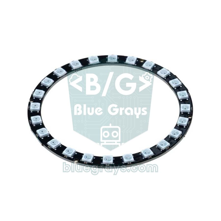
WS2812B LEDs expect a pulse of about 1.25 microseconds per bit; whether a bit is 1 or 0 is decided by how long the pulse stays HIGH. That's a textbook case for PIO. The program below is based on Raspberry Pi's official MicroPython example: the state machine runs at 8 MHz and every bit takes exactly 10 cycles, so 800,000 bits are sent per second. Thanks to autopull the machine pulls a new colour from the FIFO every 24 bits; the processor just drops the array into the FIFO with sm.put(). Change the LED count to match your strip; for how the WS2812B works and its colour order, see the WS2812B NeoPixel guide.
| WS2812B pin | Pico pin | Note |
|---|---|---|
| DIN (data in) | GP16 (physical pin 21) | A 330 ohm series resistor protects the signal |
| 5V / VCC | VBUS (pin 40) | 5 V from USB; use an external 5 V supply for many LEDs |
| GND | GND (e.g. pin 38) | The external supply's GND must be connected here too |
1# PIO ile WS2812B (NeoPixel) gökkuşağı / WS2812B (NeoPixel) rainbow with PIO
2import array
3import time
4import rp2
5from machine import Pin
6
7NUM_LEDS = 24          # halka ya da şeritteki LED sayısı / LEDs in the ring or strip
8LED_PIN = 16           # DIN bağlantısı / DIN connection
9BRIGHTNESS = 0.2       # 0.0-1.0, akımı düşük tutar / keeps current low
10
11
12@rp2.asm_pio(sideset_init=rp2.PIO.OUT_LOW, out_shiftdir=rp2.PIO.SHIFT_LEFT,
13             autopull=True, pull_thresh=24)
14def ws2812():
15    T1 = 2
16    T2 = 5
17    T3 = 3
18    wrap_target()
19    label("bitloop")
20    out(x, 1)               .side(0)    [T3 - 1]   # 1 biti al, hat LOW / take 1 bit, line LOW
21    jmp(not_x, "do_zero")   .side(1)    [T1 - 1]   # hat HIGH / line HIGH
22    jmp("bitloop")          .side(1)    [T2 - 1]   # bit 1: uzun HIGH / long HIGH
23    label("do_zero")
24    nop()                   .side(0)    [T2 - 1]   # bit 0: kısa HIGH / short HIGH
25    wrap()
26
27
28# Bit başına 10 döngü x 8 MHz = 800 kHz / 10 cycles per bit x 8 MHz = 800 kHz
29sm = rp2.StateMachine(0, ws2812, freq=8_000_000, sideset_base=Pin(LED_PIN))
30sm.active(1)
31
32pixels = array.array("I", [0] * NUM_LEDS)
33
34
35def set_pixel(i, r, g, b):
36    r = int(r * BRIGHTNESS)
37    g = int(g * BRIGHTNESS)
38    b = int(b * BRIGHTNESS)
39    pixels[i] = (g << 16) | (r << 8) | b    # WS2812B sırası GRB / byte order is GRB
40
41
42def show():
43    sm.put(pixels, 8)      # 24 biti sola hizala / left-align the 24 bits
44
45
46def wheel(pos):
47    # 0-255 arası değeri renge çevir / turn 0-255 into a colour
48    pos %= 255
49    if pos < 85:
50        return 255 - pos * 3, pos * 3, 0
51    if pos < 170:
52        pos -= 85
53        return 0, 255 - pos * 3, pos * 3
54    pos -= 170
55    return pos * 3, 0, 255 - pos * 3
56
57
58step = 0
59while True:
60    for i in range(NUM_LEDS):
61        set_pixel(i, *wheel(i * 255 // NUM_LEDS + step))
62    show()
63    step = (step + 3) % 255
64    time.sleep_ms(30)      # kare arası bekleme, aynı zamanda reset / frame gap, also the reset time
Let's follow the program line by line. out(x, 1) takes one bit from the OSR into the X register while side-set holds the line LOW (3 cycles). Then the line goes HIGH and X is checked (2 cycles). If the bit is 1, the line stays HIGH for 5 more cycles; if it's 0, the line is pulled LOW and the machine waits 5 cycles. Both paths add up to 10 cycles, which is 1.25 µs. pull_thresh=24 tells the machine to use only 24 bits of each word, which is why the colour is shifted left on the Python side (sm.put(pixels, 8)). The colour order is GRB, not RGB; if red and green are swapped, that's the reason. Because 24 LEDs at full white can draw up to 1.4 A, brightness is limited to 20% in the example.
What changed with the Pico 2 (RP2350)?
The Raspberry Pi Pico 2 is the new generation with the same size and the same pinout, but with an RP2350 chip inside. It still has two cores, but this time you can choose at boot between two Arm Cortex-M33 cores or two Hazard3 RISC-V cores. All the code in this article runs unchanged on the Pico 2: _thread is the same in MicroPython, and in the Arduino-Pico core setup1()/loop1() and rp2040.fifo keep the same names. On the PIO side a third block is added, so there are 12 state machines (0-11 in MicroPython), plus a few new instruction options.
| Feature | Pico (RP2040) | Pico 2 (RP2350) |
|---|---|---|
| Cores | 2 x Cortex-M0+ | 2 x Cortex-M33 or 2 x Hazard3 RISC-V |
| Clock speed | 133 MHz | 150 MHz |
| RAM | 264 KB | 520 KB |
| Onboard flash | 2 MB | 4 MB |
| PIO | 2 blocks, 8 state machines | 3 blocks, 12 state machines |
| Floating point | In software (fast ROM routines) | Hardware FPU (single precision) + double-precision coprocessor |
| Security | None | TrustZone, secure boot, 8 KB OTP |
| MicroPython file | RPI_PICO (.uf2) | RPI_PICO2 (.uf2) |
In practice the most noticeable difference of the Pico 2 is speed: thanks to the hardware FPU, float-heavy work (filters, sensor fusion, audio processing) runs several times faster, and twice the RAM leaves room for large display buffers. The one thing to watch is flashing the right UF2 file for the board; the Pico file doesn't run on the Pico 2. Early RP2350 versions had a known hardware issue (E9) with inputs using the internal pull-down, which was fixed in the A4 revision; using an external resistor when wiring buttons is the safe choice either way.
When do you need two cores, and when PIO?
| What you need | Best fit | Why? |
|---|---|---|
| LED brightness, servo, simple tone | Hardware PWM | Ready-made block, one line of code |
| A few sensors + display + button | One core, millis() or asyncio | No need for extra complexity |
| Smooth animation during long calculations | Two cores | The calculation on core 1 doesn't freeze the display |
| Continuous measurement alongside Wi-Fi | Two cores | Network delays don't disturb the sampling interval |
| WS2812B, extra UART, IR transmitter, encoder | PIO | Nanosecond accuracy, CPU stays free |
| VGA/DVI video, I2S audio, very fast signals | PIO + DMA | Data rates the CPU couldn't keep up with |
In short: think of the second core when jobs clash in software, and of PIO when the pins need sub-microsecond accuracy. Most hobby projects need neither; but if one day your WS2812B animation starts stuttering during a Wi-Fi request, or the board runs out of UARTs, the solution is already waiting inside the Pico.
Project ideas with Pico PIO and two cores
- Music-reactive LED ring: core 1 processes microphone samples, PIO drives the WS2812B ring and core 0 listens to the buttons.
- Eight-channel pulse generator: each state machine makes a square wave at a different frequency to feed stepper drivers or test rigs.
- Gap-free data logger: core 1 reads the ADC every 10 ms while core 0 sends the data over Wi-Fi; a slow network never costs you a sample.
- Extra serial ports: open a third and fourth UART with PIO and connect a GPS and a Bluetooth module at the same time.
- Rotary encoder counter: PIO counts encoder pulses without missing a single one; the processor only reads the result.
- Breathing night light: give smooth PWM fades to core 1 and the light sensor to core 0.
Common mistakes and how to fix them
| Symptom | Cause | Fix |
|---|---|---|
| Board doesn't respond after stopping | The loop on core 1 is still running | Use a stop flag; unplug and replug USB if needed |
| start_new_thread fails the second time | The Pico allows only one extra thread | Don't start a new one before the previous one ends |
| Variables sometimes get nonsense values | Both cores write shared data without a lock | Use allocate_lock() or the FIFO |
| StateMachine raises ValueError | freq is below system clock / 65536 | Raise the frequency and slow down with delays |
| PIOASMError: delay too large | Side-set bits shrank the delay field | Split the delay or add a nop() |
| Red and green swapped on the WS2812B | The colour order is GRB | Use the (g << 16) | (r << 8) | b format |
| setup1() never runs | The Arduino Mbed RP2040 package is selected | Install Earle Philhower's Raspberry Pi Pico/RP2040 package |
Two cores and PIO are what turn the Pico from a simple LED blinker into a serious embedded system, but they all build on the same foundation: knowing your pins, your timing and your LEDs well. In the BlueGrays app you'll find Raspberry Pi Pico projects such as LED blinking, a running light, a Knight Rider scanner, a button-driven state machine and a PWM breathing effect, each with a circuit diagram and MicroPython code, step by step, ready for you to add the techniques from this article.
Frequently asked questions
What is PIO on the Raspberry Pi Pico?
PIO (programmable I/O) is a set of small state machines in the RP2040 and RP2350 chips that run independently of the processor. Each one executes a program written in a simple nine-instruction language with cycle-accurate timing. It handles timing-critical jobs such as WS2812B LEDs, extra UARTs, IR transmission or encoder reading without keeping the CPU busy.
How many cores does the Raspberry Pi Pico have?
The RP2040 chip on the Pico and Pico W has two Cortex-M0+ cores. The RP2350 on the Pico 2 also has two cores, and at boot you can choose between Cortex-M33 and Hazard3 RISC-V cores. When your program starts only core 0 runs; you start core 1 yourself.
How many PIO state machines does the Pico have?
The RP2040 has two PIO blocks with 4 state machines each, so 8 state machines in total. Each block's 32-instruction program memory is shared by the machines in that block. The RP2350 on the Pico 2 has three PIO blocks, which means 12 state machines.
Can MicroPython use both cores of the Pico?
Yes. On the Pico, a function started with _thread.start_new_thread() runs on the second core. Only one extra thread can be open at a time, and shared data should be protected with a lock from _thread.allocate_lock(). Multicore support is still experimental in MicroPython, so it's best to avoid heavy memory work in the extra thread.
How do I use the Pico's second core in the Arduino IDE?
After installing Earle Philhower's Raspberry Pi Pico/RP2040/RP2350 package, just add setup1() and loop1() functions to your sketch; core 1 runs them automatically. 32-bit values are passed between the cores with rp2040.fifo.push() and rp2040.fifo.pop(). Arduino's Mbed-based RP2040 package doesn't have this feature.
Do I have to use PIO for WS2812B LEDs?
No. MicroPython's built-in neopixel module and the Adafruit NeoPixel library in Arduino both work fine on the Pico. The benefit of writing it yourself with PIO is that the processor stays free during transmission and you can apply the same technique to other timing-critical protocols.
Projects to build after reading this
See all projects
Raspberry Pi Pico Onboard LED Blink (Pico and Pico W)
The opening project of the Raspberry Pi Pico series! We blink the green onboard LED to verify the board works — a classic "Hello World" first experiment. NO external components, just Pico and USB cable. Code is written in MicroPython (the official language backed by Raspberry Pi Foundation). Learn machine.Pin class, Pin.OUT mode, led.on()/off() methods, and time.sleep() in Thonny IDE. Follow every toggle live in the Serial (REPL) output. Also perfect to verify
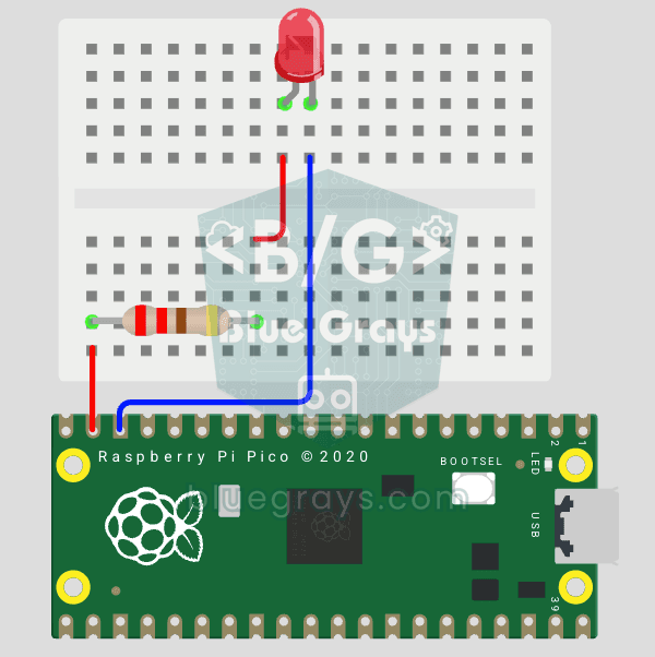
Raspberry Pi Pico: Controlling an External LED (Breadboard)
The next step after Pico’s built-in LED: connecting an external LED to the breadboard and controlling it via the GP14 pin. In this project, you’ll learn how to use any of the Pico’s general-purpose GPIO pins as an output, the LED’s polarity (long leg = anode/+, short leg = cathode/–), and why a current-limiting resistor (220Ω) is required. If you don’t include the resistor, excessive current will flow through the LED and it may burn out. The circuit is very simple: Pico GP14 → 220Ω resistor → LE
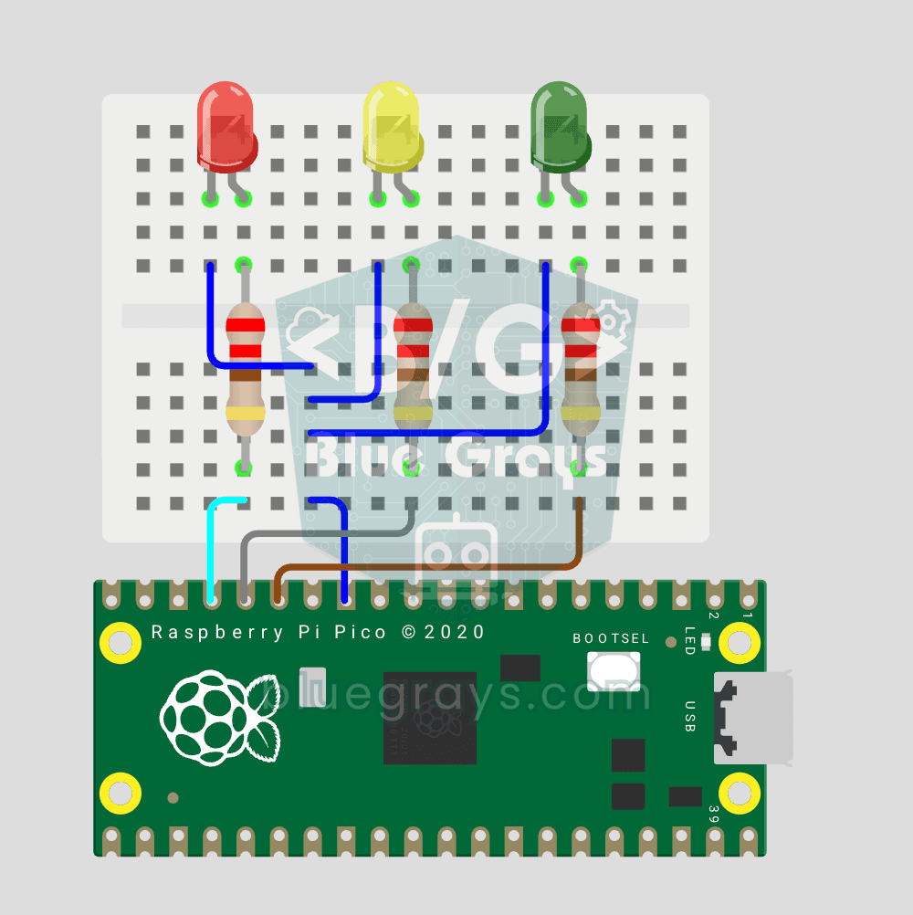
Raspberry Pi Pico Traffic Light Simulator (3 LEDs Sequential)
We simulate a real traffic light with red, yellow and green LEDs — the first 3-LED project of the Pico series! Green 4 sec "go", yellow 1.5 sec "ready", red 3 sec "stop" and red+yellow 1 sec "starting" (European traffic light pattern). Learn function definition (def all_off()), state machine logic (sequence) and multi-GPIO synchronization. Very simple circuit: 3 LEDs on GP11 (Green), GP12 (Yellow), GP13 (Red), each with a 220Ω current-limiting resistor. GP11-GP12-GP13 are ad
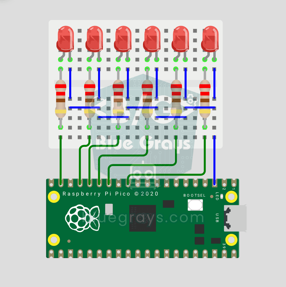
Raspberry Pi Pico Chasing LED (6 LEDs)
Classic "chasing LED" animation with Pico — 6 LED version! 6 LEDs light up left-to-right sequentially — like light walking down the row. Learn Python list, list comprehension ([Pin(p, Pin.OUT) for p in LED_PINS]), for loop with pin control and enumerate(). 6 LEDs on GP9-GP14, each with 220Ω current-limiting resistor. Very clean code: instead of defining 6 LEDs one by one, we use a list — you can add LEDs up to the number of free, usable GPIO pins, each with its own resistor. Controlling 100 inde
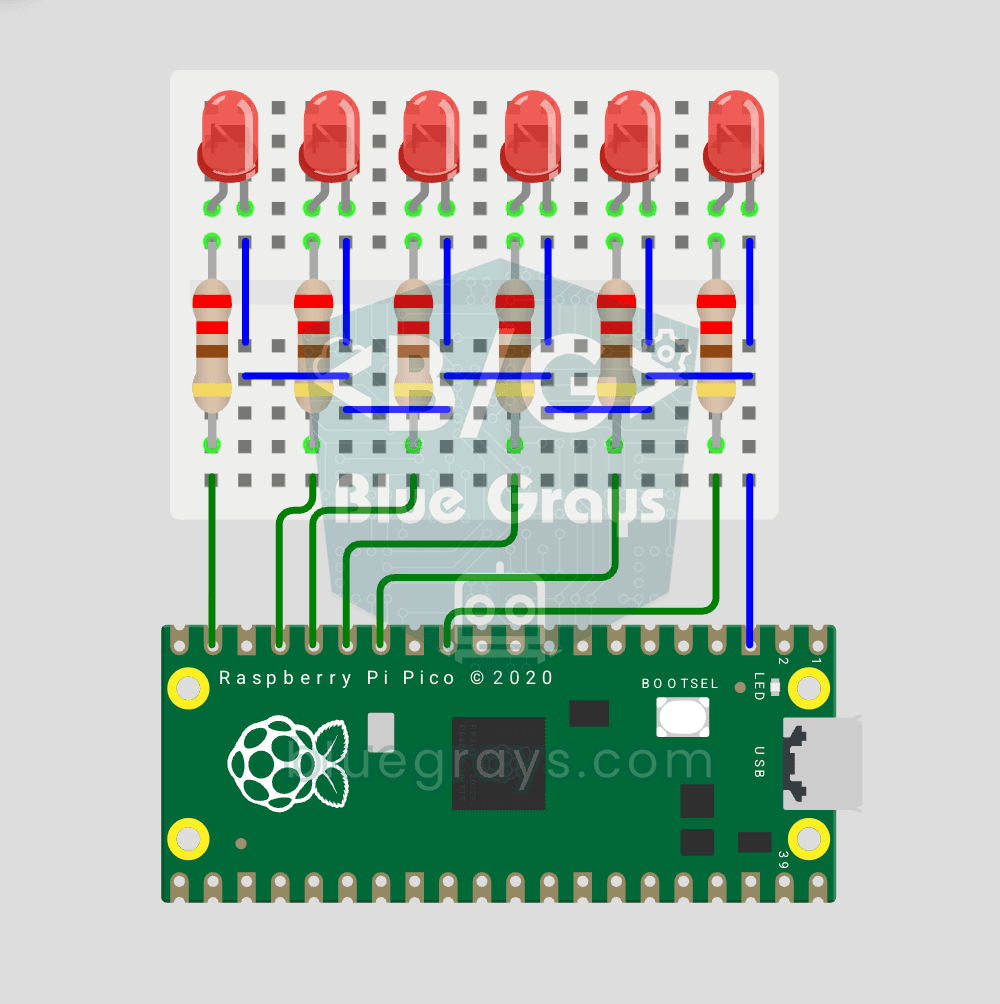
Raspberry Pi Pico Knight Rider LED Scanner (6 LED Back-Forth)
Classic "Knight Rider" LED scanner effect with Pico! 6 LEDs go left-to-right, then right-to-left, forever. Like the front grille of KITT car from the iconic 80s TV series. This project is an upgrade of the Chasing LED project: same 6 LED circuit (GP9-GP14), different code pattern. Learn reversed() function for list reversal, two separate for loops for back-and-forth pattern, and generating multiple animations on same circuit.
Raspberry Pi Pico Traffic Light with 4-Mode Button Selector (State Machine)
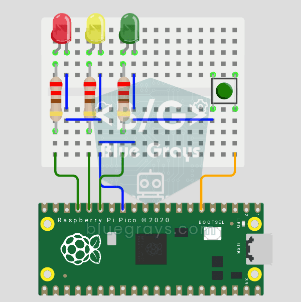
4 different traffic light modes with just 1 button! The mode changes with each press of the button: Normal cycle (red → yellow → green in sequence), Red Only (stop signal), Yellow Flash (caution/night mode), Off (maintenance). Concepts: state machine (the mode variable determines which behavior runs), modulo mode cycling ((mode + 1) % 4 → 0→1→2→3→0 infinite loop), non-blocking timing (LED phases are timed with time.ticks_ms() + time.ticks_diff(); however, the
Raspberry Pi Pico Button Debounce: IRQ vs Software Polling
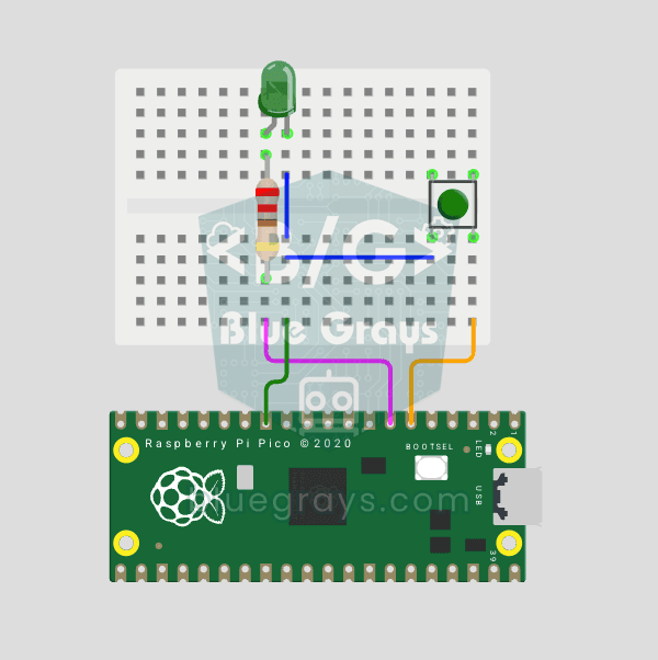
Press a button once, code counts 3-4? That is contact bounce — metal contacts oscillate for microseconds! Compare 2 counting methods side-by-side in Serial: RAW polling (catches bounce, over-counts) vs IRQ + software debounce (accurate). Learn contact bounce physics, software debounce (ticks_diff() > 50ms), Pin.irq() interrupt registration, IRQ_FALLING trigger, ISR handlers, global + ISR safety. LED toggles via IRQ (visual feedback). Serial shows both counters per press
Raspberry Pi Pico PWM LED Fade (Breathing Effect)
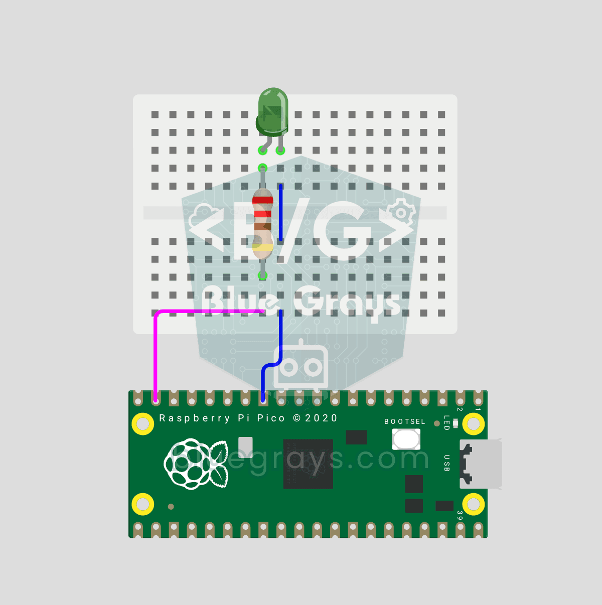
The LED no longer just blinks — it breathes! Using the Raspberry Pi Pico's PWM (Pulse Width Modulation), the LED brightness slowly rises and then slowly falls, like a sleeping MacBook's light. Learn the machine.PWM class, duty_u16() (16-bit brightness 0–65535), PWM frequency (freq(1000) — 1000 on/off cycles per second, no visible flicker), range() step loops (up and down) and analog-like output from a digital pin. PWM is a core embedded tool — RGB color mixing, motor