
What Is MicroPython? Basic Commands, REPL and First Programs
What is MicroPython and how does it differ from Python? REPL, machine.Pin, PWM, ADC, I2C, ticks_ms, main.py, Thonny, mpremote, mip, Pico and ESP32 setup.
MicroPython is a small, fast reimplementation of the Python 3 language for microcontrollers. Once you load MicroPython onto a board like the Raspberry Pi Pico or ESP32, the board runs Python code by itself: you type a command with no compile step and see the LED light up immediately. If you learned Python at school or on your computer, you can use the same syntax to read pins, drive motors, collect sensor data and connect to Wi-Fi.
In this guide you'll learn how MicroPython differs from regular Python, the REPL that lets you talk to the board instantly, and the modules you'll use most, namely machine.Pin, PWM, ADC and I2C, with example code. Then you'll see the difference between time.sleep and ticks_ms, the main.py and boot.py files that run at startup, uploading files with Thonny and mpremote, adding libraries with mip and flashing firmware to the Pico and ESP32. In the last section we compare MicroPython with Arduino C++ side by side.
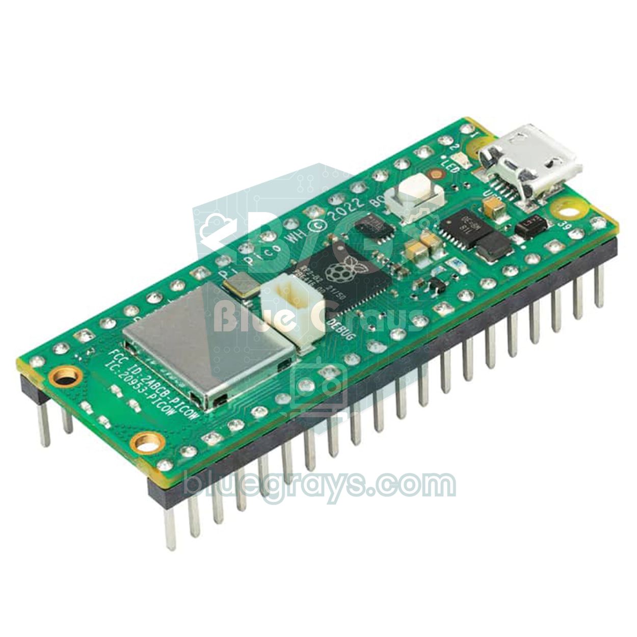
What is MicroPython and how is it different from Python?
MicroPython is an open-source project started by Damien George in 2013 for a small board, and today it supports dozens of microcontrollers. The firmware you load onto the board contains the Python interpreter, the core modules and a small file system. Your code is first turned into bytecode on the board, and then the interpreter runs that bytecode step by step. Since it's impossible to squeeze the whole of your computer's Python into a few hundred KB of RAM, the language stays the same but most libraries are either trimmed down or missing altogether. In exchange, something has been added that desktop Python doesn't have: the machine module, which gives direct access to the hardware.
| Topic | Python (computer) | MicroPython (board) |
|---|---|---|
| Where it runs | A computer with gigabytes of RAM | A microcontroller with hundreds of KB of RAM |
| Standard library | Very large: datetime, threading, urllib... | A small subset: time, os, json, re, struct, random, math... |
| Packages | numpy, pandas and thousands more via pip | No numpy or pandas; micropython-lib packages via mip |
| Hardware access | None, needs extra libraries | The machine module: Pin, PWM, ADC, I2C, SPI, UART, Timer |
| Floating-point numbers | 64-bit (about 15 digits) | 32-bit on the Pico and ESP32 (about 7 digits) |
| Time | time.time(), datetime | time.sleep_ms(), time.ticks_ms(), machine.RTC |
| Starting the program | You run it from the command line | boot.py and main.py run by themselves at startup |
Boards that run MicroPython
| Board | Firmware file | Total RAM | Note |
|---|---|---|---|
| Raspberry Pi Pico (RP2040) | RPI_PICO (.uf2) | 264 KB | The easiest board to start with |
| Raspberry Pi Pico W | RPI_PICO_W (.uf2) | 264 KB | network module for Wi-Fi; the plain Pico firmware doesn't enable Wi-Fi here |
| Raspberry Pi Pico 2 (RP2350) | RPI_PICO2 (.uf2) | 520 KB | Faster, more memory |
| ESP32 (WROOM) | ESP32_GENERIC (.bin) | 520 KB (Wi-Fi uses part of it) | Wi-Fi and Bluetooth; far more memory on models with PSRAM |
| ESP8266 (NodeMCU, Wemos D1 Mini) | ESP8266_GENERIC (.bin) | About 80 KB | Works, but memory is tight; choose an ESP32 for new projects |
| Arduino Uno (ATmega328P) | None | 2 KB | Can't run MicroPython; programmed in C++ |
Flashing MicroPython firmware to the Pico and ESP32
- Pico: Hold down the BOOTSEL button on the board while plugging in the USB cable, then release it. A drive called RPI-RP2 appears on your computer (RP2350 on the Pico 2).
- Download the right .uf2 file for your board from MicroPython's official download page (RPI_PICO for the Pico, RPI_PICO_W for the Pico W) and drag it onto that drive.
- When copying finishes, the board restarts by itself and the drive disappears; MicroPython is installed. In Thonny, choose MicroPython (Raspberry Pi Pico) under Tools > Options > Interpreter.
- ESP32: If Python is installed on your computer, type pip install esptool on the command line. Plug in the board and find its port (for example COM3 on Windows, /dev/ttyUSB0 on Linux).
- Erase the flash first: esptool.py --chip esp32 --port COM3 erase_flash. If the board won't connect, hold down the BOOT button while the command runs.
- Write the firmware: esptool.py --chip esp32 --port COM3 --baud 460800 write_flash -z 0x1000 ESP32_GENERIC-....bin. On the ESP32-S3 and ESP32-C3 the address is 0x0. Thonny's Install or update MicroPython (esptool) option does the same job from a window.
The REPL: talking to the board instantly
The REPL (Read-Eval-Print Loop) is the command line the board opens for you over the serial port. The >>> prompt you see in Thonny's Shell window at the bottom means the REPL is waiting for you. Type 1 + 1 and the board calculates and returns 2; type from machine import Pin followed by Pin("LED", Pin.OUT).value(1) and the Pico's LED lights up at that very moment. There's no faster way than the REPL to read a sensor value, check whether a pin is wired correctly or explore how a library works, all without waiting to compile and upload.
| Shortcut or command | What it does |
|---|---|
| Ctrl+C | Stops the running program (KeyboardInterrupt) and returns to the REPL |
| Ctrl+D | Soft reset; boot.py and main.py run again |
| Ctrl+E | Paste mode: paste long code without breaking the indentation, run it with Ctrl+D |
| Tab | Auto-completion; type machine. and press Tab to list everything in the module |
| help("modules") | Lists every module in the firmware |
| import gc; gc.mem_free() | Shows the free RAM available to your program, in bytes |
| import os; os.listdir() | Lists the files on the board |
First program and its Arduino C++ equivalent
1# İlk program: dahili LED'i yakıp söndür / First program: blink the onboard LED
2from machine import Pin
3import time
4
5led = Pin("LED", Pin.OUT)        # Pico ve Pico W; ESP32'de Pin(2, Pin.OUT) / Pico and Pico W; Pin(2, Pin.OUT) on ESP32
6
7while True:
8    led.value(1)                 # yak / on
9    time.sleep(0.5)              # saniye cinsinden / in seconds
10    led.value(0)                 # söndür / off
11 time.sleep(0.5)1// Aynı program Arduino C++ ile / The same program in Arduino C++
2void setup() {
3 pinMode(LED_BUILTIN, OUTPUT);
4}
5
6void loop() {
7 digitalWrite(LED_BUILTIN, HIGH);
8 delay(500); // milisaniye cinsinden / in milliseconds
9 digitalWrite(LED_BUILTIN, LOW);
10 delay(500);
11}The two programs do the same job but are structured differently. MicroPython has no setup() or loop(): the file runs once from top to bottom, and you build the endless loop yourself with while True:. Instead of curly braces and semicolons it uses indentation; every line inside the loop must be indented by the same amount (usually 4 spaces). The delay uses a different unit too: time.sleep(0.5) takes seconds, while Arduino's delay(500) takes milliseconds. In MicroPython you use time.sleep_ms() for milliseconds and time.sleep_us() for microseconds. The basics of the Arduino side are in Arduino programming basics.
machine.Pin: digital input and output
| MicroPython | Arduino C++ equivalent | Description |
|---|---|---|
| led = Pin(15, Pin.OUT) | pinMode(15, OUTPUT) | Makes the pin an output |
| led.value(1) or led.on() | digitalWrite(15, HIGH) | Sets the pin HIGH; value(0) or off() sets it LOW |
| buton = Pin(14, Pin.IN, Pin.PULL_UP) | pinMode(14, INPUT_PULLUP) | Input with the internal pull-up resistor |
| buton.value() | digitalRead(14) | Returns 0 or 1 |
| led.toggle() | digitalWrite(15, !digitalRead(15)) | Inverts the state; available on the Pico, use value(not led.value()) on the ESP32 |
| buton.irq(trigger=Pin.IRQ_FALLING, handler=f) | attachInterrupt(..., f, FALLING) | Calls the function f when the pin changes |
time.sleep and ticks_ms: measuring time without blocking
time.sleep() makes the board wait completely; meanwhile no button is read and no sensor is checked. To run several jobs at once you use the MicroPython equivalent of Arduino's millis() approach: time.ticks_ms() gives the milliseconds since startup, and time.ticks_diff(new, old) calculates the difference between two moments. It matters that you get the difference with ticks_diff rather than plain subtraction; the counter wraps around after reaching a certain value, and plain subtraction gives the wrong result at that point. The code below blinks the LED without blocking while listening to a button through an interrupt (IRQ); each press changes the blink speed.
1# delay kullanmadan iki iş: LED yanıp söner, buton kesmeyle modu değiştirir
2# Two jobs without blocking: the LED blinks, a button interrupt switches the mode
3from machine import Pin
4import time
5
6led = Pin(15, Pin.OUT)                       # LED + 220 Ω, GP15
7buton = Pin(14, Pin.IN, Pin.PULL_UP)         # buton GP14 ile GND arasında / button between GP14 and GND
8
9hizli = False
10son_basma = 0
11son_degisim = time.ticks_ms()
12
13def buton_kesme(pin):                        # kesme fonksiyonu kısa olmalı / keep the handler short
14    global hizli, son_basma
15    simdi = time.ticks_ms()
16    if time.ticks_diff(simdi, son_basma) > 200:   # 200 ms debounce / 200 ms debounce
17        son_basma = simdi
18        hizli = not hizli
19
20buton.irq(trigger=Pin.IRQ_FALLING, handler=buton_kesme)   # basınca HIGH'dan LOW'a iner / goes HIGH to LOW when pressed
21
22while True:
23    aralik = 100 if hizli else 500
24    if time.ticks_diff(time.ticks_ms(), son_degisim) >= aralik:   # taşmaya karşı güvenli / safe against wrap-around
25        son_degisim = time.ticks_ms()
26        led.value(not led.value())
27 # burada başka işler yapılabilir / other work can run herePWM: brightness, servos and sound
1# PWM: LED parlaklığı ve servo açısı / PWM: LED brightness and servo angle
2from machine import Pin, PWM
3import time
4
5led = PWM(Pin(15))
6led.freq(1000)                               # 1 kHz: titreme görünmez / no visible flicker
7
8for d in range(0, 65536, 2048):              # duty_u16: 0 (kapalı) ... 65535 (tam) / 0 (off) ... 65535 (full)
9    led.duty_u16(d)
10    time.sleep_ms(20)
11led.duty_u16(0)
12
13servo = PWM(Pin(16))
14servo.freq(50)                               # servolar 50 Hz (20 ms) ister / servos expect 50 Hz (20 ms)
15
16def servo_aci(derece):
17    us = 500 + derece * 2000 // 180          # 0° = 0,5 ms, 180° = 2,5 ms; servona göre ayarla / tune for your servo
18    servo.duty_ns(us * 1000)
19
20for a in (0, 90, 180, 90):
21    servo_aci(a)
22    time.sleep(1)
The PWM object switches a pin on and off very quickly to set an average power. freq() sets how many times per second this repeats, and duty_u16() sets how long the pin stays on with a number between 0 and 65535; 32768 means roughly 50 percent. This scale gives much finer steps than the 0–255 range of Arduino's analogWrite. Servos expect a 50 Hz signal and a pulse width between 0.5 and 2.5 ms; duty_ns() sets the pulse length directly in nanoseconds, which makes servo code much simpler. You can also play notes by giving a passive buzzer different freq() values. Duty cycle and frequency are explained in detail in What is PWM.
ADC: analog reading
1# ADC: potansiyometre ve Pico'nun dahili sıcaklık sensörü
2# ADC: a potentiometer and the Pico's internal temperature sensor
3from machine import ADC, Pin
4import time
5
6pot = ADC(Pin(26))                           # GP26 = ADC0; ESP32'de ADC(Pin(34)) / ADC(Pin(34)) on ESP32
7yonga = ADC(4)                               # 4. kanal: dahili sıcaklık / channel 4: internal temperature
8
9def ortalama(adc, n=16):                     # gürültüyü azalt / reduce noise
10    toplam = 0
11    for _ in range(n):
12        toplam += adc.read_u16()
13    return toplam // n
14
15while True:
16    ham = ortalama(pot)                      # 0-65535 (12 bit ölçüm 16 bite ölçeklenir) / 12-bit reading scaled to 16 bits
17    volt = ham * 3.3 / 65535
18    v_t = ortalama(yonga) * 3.3 / 65535
19    derece = 27 - (v_t - 0.706) / 0.001721   # RP2040 veri sayfasındaki formül / formula from the RP2040 datasheet
20    print("Pot: {} ({:.2f} V)  Yonga / chip: {:.1f} C".format(ham, volt, derece))
21    time.sleep(1)
read_u16() returns a value between 0 and 65535 on every board, so the same code runs on the Pico and the ESP32. The Pico's ADC is actually 12-bit, and the reading is scaled to 16 bits. The Pico has three user-accessible analog pins: GP26 (ADC0), GP27 (ADC1) and GP28 (ADC2); the fourth channel is the temperature sensor inside the chip, and it measures the chip's temperature, not the room's. On the ESP32 you need adc.atten(ADC.ATTN_11DB) to read the full 0–3.3 V range, and the ADC2 pins can't be used while Wi-Fi is on, so pick the ADC1 pins between GPIO 32 and 39. The 16-sample average in the code noticeably reduces ADC noise. Concepts such as resolution and reference voltage are covered in What is an ADC.
I2C: connecting sensors and displays
1# I2C: hattı tara ve SSD1306 OLED'e yaz / I2C: scan the bus and write to an SSD1306 OLED
2from machine import Pin, I2C
3import ssd1306                               # önce: mpremote mip install ssd1306 / first: mpremote mip install ssd1306
4
5i2c = I2C(0, sda=Pin(4), scl=Pin(5), freq=400000)   # Pico; ESP32'de I2C(0, sda=Pin(21), scl=Pin(22))
6adresler = i2c.scan()
7print("Bulunan / found:", [hex(a) for a in adresler])   # OLED genelde 0x3c / OLED is usually 0x3c
8
9if 0x3C in adresler:
10    oled = ssd1306.SSD1306_I2C(128, 64, i2c)
11    oled.fill(0)
12    oled.text("MicroPython", 0, 0)
13    oled.text("I2C: " + hex(adresler[0]), 0, 16)
14    oled.show()
I2C(0, sda=..., scl=...) starts the hardware I2C unit on the pins you choose, and scan() returns a list of the addresses of every device that answers on the bus. If a sensor isn't working, this scan is the first thing to do: an empty list means the problem is in the wiring, and an unexpected address means you fix the address in the code. On the Pico the pins each I2C unit can use are fixed; for example the GP0-GP1, GP4-GP5 or GP8-GP9 pairs work for I2C0, and choosing a wrong pair gives a ValueError. On the ESP32, I2C can be assigned to almost any pin. Display details are in OLED display, and the protocol itself in What is I2C.
main.py and boot.py: code that runs at startup
When you press Run in Thonny, the code only runs at that moment without being saved to the board; it's gone when you unplug the USB. For your code to run by itself every time the board starts, you must save the file on the board as main.py. At startup boot.py runs first, then main.py. boot.py is for one-off preparations such as connecting to Wi-Fi or setting the clock; the ESP32 firmware creates this file by itself, while on the Pico it usually doesn't exist. Your actual program always lives in main.py. You can bring functions you wrote in other files into main.py with import, and save readings to the board's file system with open().
1# main.py: kart her açıldığında otomatik çalışır / runs automatically every time the board starts
2import time
3from machine import Pin
4
5time.sleep(3)                                # Ctrl+C ile durdurmak için güvenlik payı / a safety window for Ctrl+C
6led = Pin("LED", Pin.OUT)
7sayac = 0
8
9try:
10    while True:
11        sayac += 1
12        led.value(sayac % 2)
13        print("Calisiyor / running", sayac)
14        time.sleep(1)
15except KeyboardInterrupt:                    # Thonny'de Stop ya da Ctrl+C / Stop in Thonny or Ctrl+C
16    led.value(0)
17 print("Durduruldu / stopped")Uploading files: Thonny and mpremote
If you're just starting out, Thonny is the easiest way: write your code, choose File > Save as, pick Raspberry Pi Pico or MicroPython device in the window that opens and name the file main.py. Open View > Files and you'll see the files on your computer and on the board side by side, and you can copy from one to the other with a right-click. For those who like the command line and use an editor such as VS Code, the official tool is mpremote; install it with pip install mpremote and it connects automatically to the first MicroPython board it finds.
| mpremote command | What it does |
|---|---|
| mpremote | Connects to the first board it finds and opens the REPL (exit: Ctrl+X) |
| mpremote ls | Lists the files on the board |
| mpremote cp main.py :main.py | Copies a file from the computer to the board; the colon (:) means the board |
| mpremote run test.py | Runs the file without saving it to the board and shows its output |
| mpremote mip install ssd1306 | Downloads the library over the computer's internet and installs it in the board's /lib folder |
| mpremote reset | Restarts the board |
| mpremote connect COM3 ls | Connects to the board on a specific port (such as /dev/ttyACM0 on macOS and Linux) |
Adding libraries: mip
There's no pip in MicroPython; the small package manager mip is used instead. On a board that can get online, such as a Pico W or ESP32, you first connect to Wi-Fi and then type import mip and mip.install("ssd1306") in the REPL; the package is downloaded from the official micropython-lib repository and placed in the board's /lib folder. You can also install a driver from GitHub with mip.install("github:user/repo"). For a Pico without Wi-Fi, do the same from your computer with the mpremote mip install command or Thonny's Tools > Manage packages menu. Copying a single-file driver (for example a .py file written for a sensor) to the board also works; as long as the file sits in the root or in /lib, you can load it with import. The Wi-Fi connection steps are in Pico W Wi-Fi.
MicroPython or Arduino C++?
| Feature | MicroPython | Arduino C++ |
|---|---|---|
| Language | Python 3 syntax | C++ and the Arduino core |
| How it runs | An interpreter on the board runs bytecode | Compiled to machine code on the computer |
| Turnaround | Instant in the REPL; saving takes 1–2 seconds | Compile and upload on every change, 10–60 seconds |
| Speed | Pure Python loops are roughly 10–100 times slower | Native speed |
| Timing | The garbage collector occasionally makes short pauses | Predictable down to microseconds |
| File system | Yes: main.py, data and settings files | No; needs EEPROM or an extra library |
| Libraries | micropython-lib and community drivers | The huge Arduino library ecosystem |
| Boards | Pico, ESP32, ESP8266 | Almost all of them, including Uno, Nano and Mega |
| Error messages | Clear messages with line numbers at run time | Compile errors; Serial.print to follow it at run time |
| Best at | Learning, quick experiments, Wi-Fi and data handling | Precise timing, low-memory boards, plenty of ready-made libraries |
In practice your project decides. Reading a sensor and sending it over Wi-Fi, serving a web page or driving a display takes fewer lines and gets done faster in MicroPython. Generating signals with microsecond precision, updating hundreds of LEDs very quickly or only having a small board like an Uno puts C++ ahead. You can speed up a slow function with the @micropython.native decorator, and reduce garbage-collector pauses by avoiding creating new lists and strings inside loops. For choosing a board, also see Arduino or ESP32.
Common errors and fixes
| Error or symptom | Cause | Fix |
|---|---|---|
| ImportError: no module named 'ssd1306' | The library isn't on the board | Install it with mip or mpremote mip, or copy the .py file to the board |
| IndentationError | Inconsistent indentation, spaces and tabs mixed | Use 4 spaces throughout the file; Thonny does this for you |
| OSError: [Errno 5] EIO (I2C) | The device doesn't answer: wiring, address or power | Check the address with scan(), verify SDA and SCL |
| ValueError: bad SCL pin | The chosen pins don't belong to that I2C unit | Pick the correct I2C0 or I2C1 pair from the Pico pinout |
| The code runs in Thonny but not after unplugging USB | The file wasn't saved to the board as main.py | Use Save as to save it on the board as main.py |
| MemoryError: memory allocation failed | RAM is full: a big list, a long string or a large buffer | Process data in chunks, call gc.collect(), use bytearray |
| Thonny: Device is busy or does not respond | main.py is in a loop with no pause, or another program is using the port | Stop or Ctrl+C, close the other program, wipe the flash if needed |
MicroPython is the shortest route into the microcontroller world if you already know Python: you see the result the moment you try a pin in the REPL, and a few lines are enough to read a sensor and connect to Wi-Fi. Once you've learned the core modules, the main.py idea and non-blocking timing with ticks_ms, your projects grow quickly. In the BlueGrays app you'll find Raspberry Pi Pico projects with LEDs, a traffic light, buttons and PWM, with step-by-step wiring diagrams and MicroPython code.
Frequently asked questions
What is MicroPython?
MicroPython is a small version of the Python 3 language made for microcontrollers. Thanks to the firmware loaded onto the board, boards like the Raspberry Pi Pico and ESP32 run Python code directly; the machine module gives you access to pins, PWM, the ADC and I2C.
Is MicroPython the same as Python?
The syntax is the same, but MicroPython is a trimmed-down subset of desktop Python. Large libraries such as numpy and pandas are missing, the standard library is reduced and floating-point numbers are 32-bit on the Pico and ESP32. In return, the machine module has been added for direct hardware access.
Which is better, MicroPython or Arduino?
It depends on your goal. MicroPython is more comfortable for learning, quick experiments and projects that send data over Wi-Fi; Arduino C++ runs faster, has more precise timing and offers far more ready-made libraries. The Pico and ESP32 can be programmed either way.
Does MicroPython run on an Arduino Uno?
No. The ATmega328P chip on the Arduino Uno has only 2 KB of RAM and 32 KB of flash, and the MicroPython interpreter doesn't fit. If you want to use MicroPython, choose a more powerful board such as the Raspberry Pi Pico or ESP32.
How do I install a library in MicroPython?
On a board connected to the internet, type import mip and mip.install("package_name") in the REPL. On boards without Wi-Fi, do the same from your computer with the mpremote mip install package_name command or with Thonny's package manager. Copying single-file drivers to the board also works.
How do I save code permanently on the Pico?
In Thonny, choose Raspberry Pi Pico from File > Save as and name the file main.py. Every time the board starts, boot.py runs first and then main.py runs by itself; even if you unplug the USB from the computer and plug it into another 5 V source, the program keeps running.
Projects to build after reading this
See all projects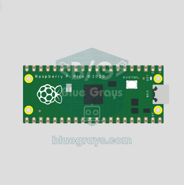
Raspberry Pi Pico Onboard LED Blink (Pico and Pico W)
The opening project of the Raspberry Pi Pico series! We blink the green onboard LED to verify the board works — a classic "Hello World" first experiment. NO external components, just Pico and USB cable. Code is written in MicroPython (the official language backed by Raspberry Pi Foundation). Learn machine.Pin class, Pin.OUT mode, led.on()/off() methods, and time.sleep() in Thonny IDE. Follow every toggle live in the Serial (REPL) output. Also perfect to verify
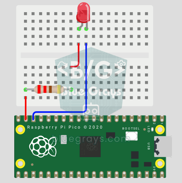
Raspberry Pi Pico: Controlling an External LED (Breadboard)
The next step after Pico’s built-in LED: connecting an external LED to the breadboard and controlling it via the GP14 pin. In this project, you’ll learn how to use any of the Pico’s general-purpose GPIO pins as an output, the LED’s polarity (long leg = anode/+, short leg = cathode/–), and why a current-limiting resistor (220Ω) is required. If you don’t include the resistor, excessive current will flow through the LED and it may burn out. The circuit is very simple: Pico GP14 → 220Ω resistor → LE
Raspberry Pi Pico Alternating Two LEDs (Blink-Flip Pattern)
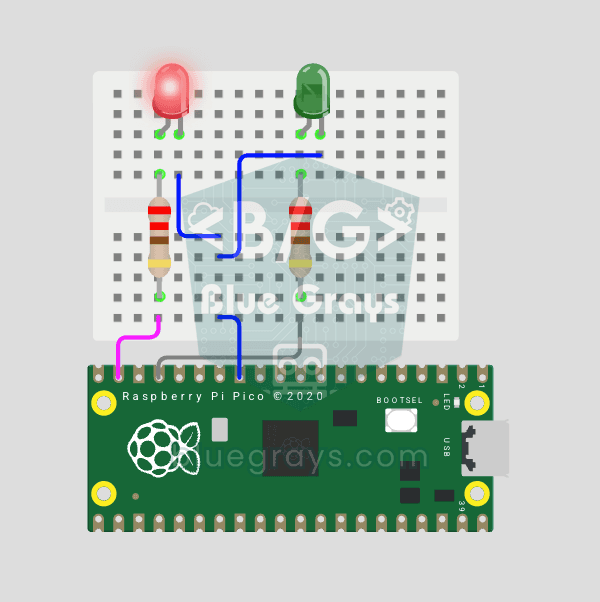
The next step after single LED on Pico: two LEDs blink alternately in a classic flip-flop pattern. When one turns off, the other lights up — the most basic example of multi-GPIO coordination. In this project two different color LEDs (red on GP14, green on GP13) swap states every 500ms. MicroPython's Pin.toggle() method makes the code short and clear. The same core logic is the foundation of traffic lights, police strobes, chasing LEDs and all multi-LED animations. Very simple circuit: 220Ω res
Raspberry Pi Pico Traffic Light Simulator (3 LEDs Sequential)
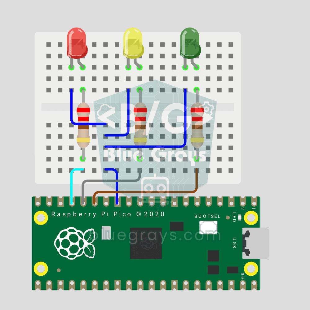
We simulate a real traffic light with red, yellow and green LEDs — the first 3-LED project of the Pico series! Green 4 sec "go", yellow 1.5 sec "ready", red 3 sec "stop" and red+yellow 1 sec "starting" (European traffic light pattern). Learn function definition (def all_off()), state machine logic (sequence) and multi-GPIO synchronization. Very simple circuit: 3 LEDs on GP11 (Green), GP12 (Yellow), GP13 (Red), each with a 220Ω current-limiting resistor. GP11-GP12-GP13 are ad
Raspberry Pi Pico Button Controlled LED (Push)
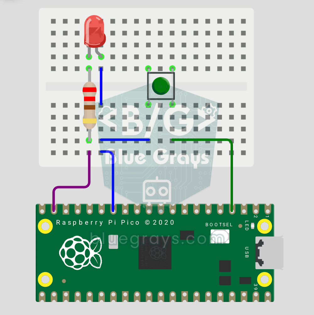
First input project with Pico — button read! LED lights while button is pressed, off when released. This is the big step after LED animations: signal input from the world to Pico. Learn Pin.IN (input mode), Pin.PULL_UP (internal pull-up resistor — standard for buttons), button.value() reading. GP14 LED, GP2 button (internal PULL_UP). Pressed = LOW (0), released = HIGH (1) — reverse logic seems confusing at first but is industry standard.
Raspberry Pi Pico Button Debounce: IRQ vs Software Polling
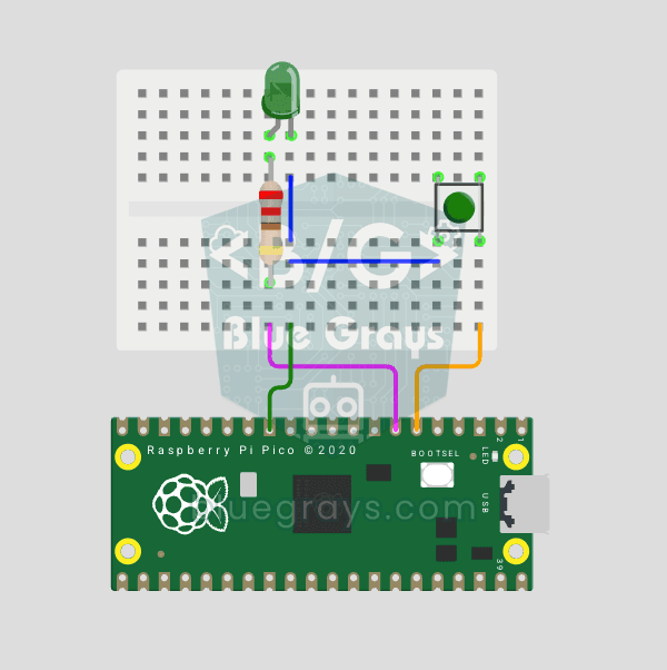
Press a button once, code counts 3-4? That is contact bounce — metal contacts oscillate for microseconds! Compare 2 counting methods side-by-side in Serial: RAW polling (catches bounce, over-counts) vs IRQ + software debounce (accurate). Learn contact bounce physics, software debounce (ticks_diff() > 50ms), Pin.irq() interrupt registration, IRQ_FALLING trigger, ISR handlers, global + ISR safety. LED toggles via IRQ (visual feedback). Serial shows both counters per press
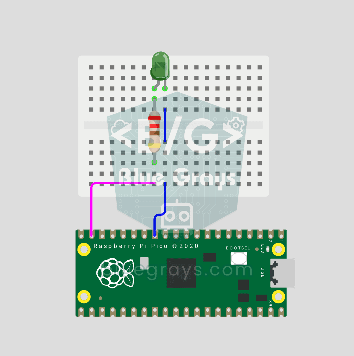
Raspberry Pi Pico PWM LED Fade (Breathing Effect)
The LED no longer just blinks — it breathes! Using the Raspberry Pi Pico's PWM (Pulse Width Modulation), the LED brightness slowly rises and then slowly falls, like a sleeping MacBook's light. Learn the machine.PWM class, duty_u16() (16-bit brightness 0–65535), PWM frequency (freq(1000) — 1000 on/off cycles per second, no visible flicker), range() step loops (up and down) and analog-like output from a digital pin. PWM is a core embedded tool — RGB color mixing, motor
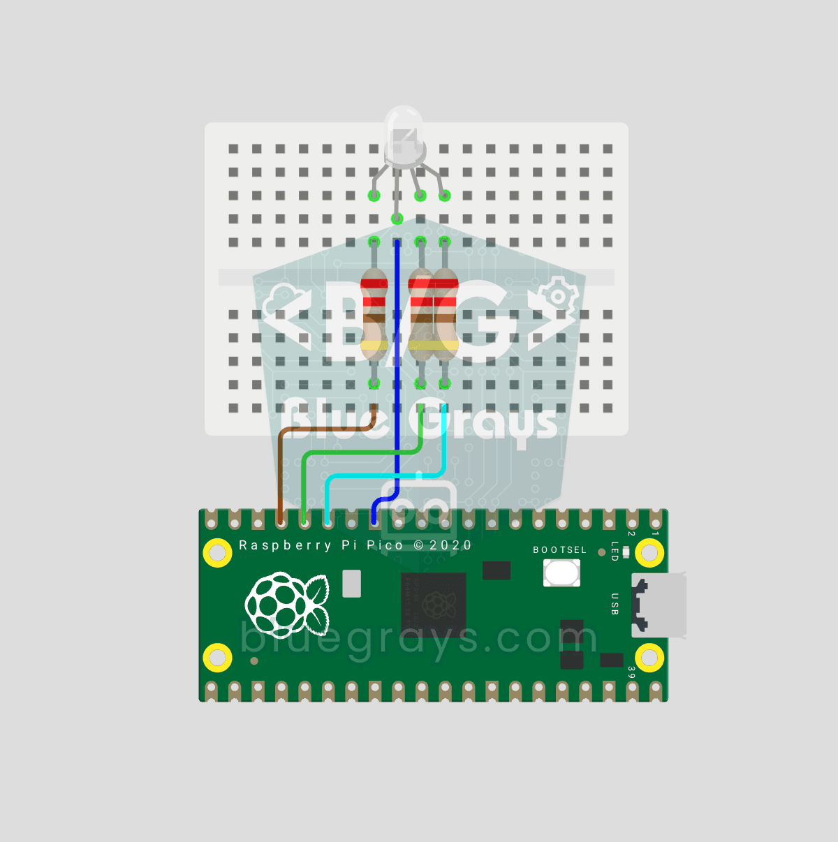
Raspberry Pi Pico RGB LED Color Cycle (3-Channel PWM)
One LED, millions of colors! An RGB LED actually contains 3 LEDs: red, green and blue. Driving each with its own Pico PWM channel mixes the colors: red + green = yellow, green + blue = cyan, all three = white. Here the LED cycles through 8 colors. Learn multiple PWM channels, defining functions (def set_color(...)), RGB color mixing (how screens and smart bulbs work), 8-bit → 16-bit conversion (x257 maps 0–255 to 0–65535), common cathode vs common anode LEDs