
What Is an Inductor? Inductance, Henry, Coil Codes and Uses
What is an inductor? Inductance and henry, energy storage, colour and SMD codes, buck-boost and LC filters, relay back EMF and flyback diode, Arduino meter.
The short answer to what is an inductor is this: an inductor (coil) is a component made by winding a conductive wire into loops, and it resists changes in the current flowing through it. When current flows, a magnetic field forms around it and the inductor stores energy in that field; when the current tries to drop, it gives the energy back and tries to keep the current going. Thanks to this simple property you'll find inductors in step-down and step-up modules, noise filters, radio circuits, relays, motors and transformers.
In this article you'll learn how an inductor works, what inductance and its unit, the henry, mean, how it differs from a capacitor, how much energy it stores and what its time constant is. Step by step we'll cover reading values from colour and SMD codes, the role of inductors in buck and boost converters and LC filters, back EMF in relay and motor coils and the diode that tames it, estimating inductance from the number of turns, and building a simple inductance meter with an Arduino.
What is an inductor and how does it work?
When current flows through a wire, a magnetic field forms around it. If the wire is wound into loops instead of running straight, the fields of all the turns add up and a strong, concentrated field forms inside the coil. The interesting part is what happens when this field changes. According to Faraday's law, a changing magnetic field induces a voltage in the wire; according to Lenz's law, that voltage always opposes the change. Try to increase the current and the inductor produces an opposing voltage that slows the rise; try to cut the current and it produces a voltage in the same direction to keep the current flowing.
You can compare it to a flywheel: a heavy flywheel is hard to get spinning and, once spinning, hard to stop. An inductor does the same for current. A capacitor does exactly the opposite for voltage: it doesn't let the voltage change suddenly. That's why the two are often used together in electronics and are thought of almost as twins. If you haven't read about capacitors yet, the what is a capacitor guide makes this comparison easier to follow.
| Property | Inductor (coil) | Capacitor |
|---|---|---|
| Where does it store energy? | In a magnetic field | In an electric field |
| What sudden change does it resist? | Current | Voltage |
| Basic formula | V = L × di/dt | I = C × dV/dt |
| With direct current (DC) | Like a short circuit (only wire resistance) | Like an open circuit (no current) |
| As frequency rises | Its resistance (reactance) rises | Its resistance (reactance) falls |
| Unit | Henry (H) | Farad (F) |
| Symbol | L | C |
Inductance and its unit, the henry
How strongly an inductor resists changes in current is set by its inductance; the symbol is L and the unit is the henry (H). The definition: an inductor has an inductance of 1 henry if a current change of 1 ampere per second produces 1 volt across its terminals. As a formula it's written V = L × di/dt. One henry is a very large value in electronics; in hobby circuits you'll mostly meet inductors in the microhenry (µH) and millihenry (mH) range.
| Unit | In henries | Where you'll see it |
|---|---|---|
| Nanohenry (nH) | 0.000000001 H | Wi-Fi, Bluetooth and radio circuits, SMD chip inductors |
| Microhenry (µH) | 0.000001 H | Buck and boost modules, filters, LoRa and RF modules |
| Millihenry (mH) | 0.001 H | Audio filters, relay coils, common-mode chokes |
| Henry (H) | 1 H | Old power supply chokes, windings of large transformers |
Inductance depends on four things: the number of turns (N), the coil's cross-sectional area, its length and the material of the core inside it. The most important is the number of turns, because inductance grows with the square of the turns: double the turns and the inductance quadruples. Putting a ferrite or iron powder core inside the coil raises the inductance tens or even hundreds of times for the same number of turns, which is why a small ferrite inductor can have a higher value than a large air-core one.
Storing energy in a magnetic field and the time constant
An inductor carrying current holds E = ½ × L × I² of energy in its magnetic field. For example, a 33 µH power inductor carrying 3 A stores 0.5 × 0.000033 × 9 = about 150 microjoules. That looks tiny, but a buck converter fills and empties this energy 150,000 times a second and so moves watts of power from one side to the other. Because the energy grows with the square of the current, doubling the current quadruples the stored energy.
When you put an inductor in series with a resistor and apply a voltage, the current doesn't jump up instantly; it rises gradually. The speed of this rise is set by the time constant: τ = L / R. A 10 mH inductor in series with a 100 Ω resistor has τ = 0.01 / 100 = 100 µs. This is the inductor counterpart of the RC time constant of a capacitor and follows the same percentages:
| Elapsed time | Current as a share of its final value |
|---|---|
| 1 τ | 63% |
| 2 τ | 86% |
| 3 τ | 95% |
| 4 τ | 98% |
| 5 τ | 99% (complete in practice) |
Inductive reactance: how does an inductor behave with AC?
With direct current an inductor only shows the resistance of its wire; this value is called DCR (DC resistance) and on a good power inductor it's a few tens of milliohms. With alternating current, however, the current keeps changing, the inductor resists it, and a frequency-dependent resistance called inductive reactance appears: XL = 2 × π × f × L. A 10 mH inductor shows only 2 × 3.14 × 50 × 0.01 = 3.14 Ω at 50 Hz but 6283 Ω at 100 kHz. In short, an inductor passes low frequencies and DC easily and holds back high frequencies. A capacitor does the opposite; the secret of filters is using the two together.
Types of inductors
| Type | Appearance | Typical use |
|---|---|---|
| Air core | Hollow, thick wire winding | Radio transmitters, high-frequency circuits |
| Ferrite rod | Wire wound on a rod | AM radio antennas, filters |
| Toroid (ring) | Wound on a ring-shaped core | Power supplies, chokes, little magnetic leakage |
| Axial (colour coded) | Looks like a resistor, with colour bands | Filters, older circuits, kits |
| SMD chip inductor | Tiny rectangle, with a code or no marking at all | Phones, Wi-Fi and Bluetooth modules |
| Power inductor (shielded or unshielded) | Square or cylindrical, marked with codes like 330 or 101 | Buck and boost modules, DC-DC converters |
| Common-mode choke | A ring with two windings | Noise suppression on USB and power inputs |
| Relay and solenoid coil | An electromagnet that pulls a mechanism | Relays, locks, valves, buzzers |
Reading inductor values from colour codes
Axial inductors look very much like resistors and are read with the same colour chart; the only difference is that the result is in microhenries (µH) rather than ohms. The first two bands give the digits, the third the multiplier and the fourth the tolerance. For example, brown-black-black means 10 × 1 = 10 µH, brown-black-brown 10 × 10 = 100 µH, yellow-violet-black 47 µH and red-red-gold 22 × 0.1 = 2.2 µH. In the tolerance band, gold means ±5%, silver ±10% and black ±20%. You don't have to memorise the colours: find the digits with the resistor colour code tool and read the result as µH. On some military-standard inductors the first band is wide and silver; it marks the standard rather than the value and is skipped when reading.
SMD inductor codes: what do 101, 4R7 and 47N mean?
SMD power inductors and chip inductors usually carry a three-character code, and again the value is in µH. In a three-digit code the first two digits give the number and the third gives how many zeros to add. The letter R marks the decimal point in µH and the letter N marks the decimal point in nanohenries. Instead of decoding by hand you can use the inductor code tool.
| Code | Calculation | Value |
|---|---|---|
| 100 | 10 × 10⁰ | 10 µH |
| 101 | 10 × 10¹ | 100 µH |
| 102 | 10 × 10² | 1000 µH = 1 mH |
| 220 | 22 × 10⁰ | 22 µH |
| 330 | 33 × 10⁰ | 33 µH |
| 4R7 | 4.7 | 4.7 µH |
| R47 | 0.47 | 0.47 µH = 470 nH |
| 47N | 47 nH | 0.047 µH |
| 2N2 | 2.2 nH | 0.0022 µH |
The inductor's role in buck and boost converters
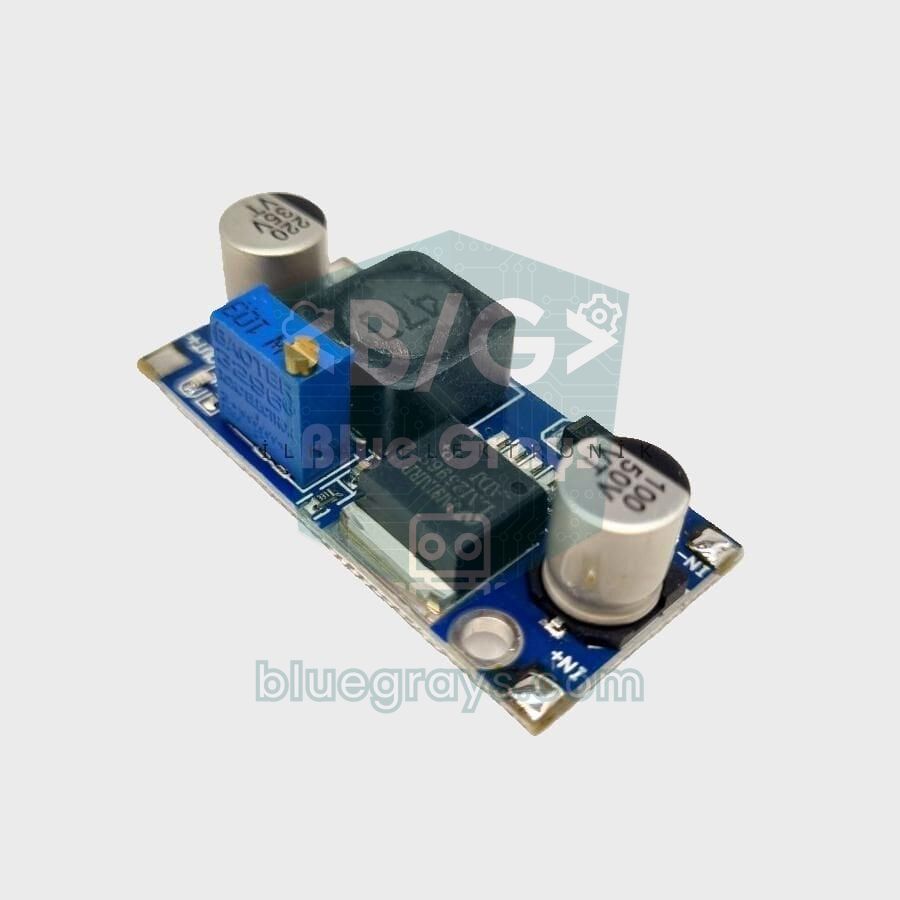
Switching step-down (buck) and step-up (boost) converters use the inductor's ability to store energy to convert voltage without burning it off as heat. In a buck converter a transistor switches on and off tens of thousands of times a second. While the transistor is on, current flows through the inductor to the load and the inductor stores energy; when the transistor turns off, the inductor delivers its stored energy to the load through a diode to keep the current flowing. The output capacitor smooths the ripple. Ideally the output voltage is set by the fraction of time the transistor is on (D, the duty cycle): Vout = D × Vin for a buck and Vout = Vin / (1 − D) for a boost. That's why a module like the LM2596 turns 12 V into 5 V at 80–90% efficiency, whereas a linear regulator like the 7805 turns the 7 V difference into heat.
When choosing an inductor, the two most important values are the inductance and the saturation current (Isat). The current through the inductor rises and falls a little with every switching cycle; this ripple is found with ΔI = (Vin − Vout) × D / (f × L). Suppose an LM2596 running at 150 kHz drops 12 V to 5 V with a 33 µH inductor: D = 5 / 12 = 0.42, ΔI = 7 × 0.42 / (150,000 × 0.000033) ≈ 0.59 A. With a 2 A load the peak current through the inductor is 2 + 0.3 = 2.3 A, and the inductor's saturation current must be above that. A saturated inductor suddenly loses its inductance, the current rises uncontrolled, and the module heats up and whines. To use the module correctly, see the LM2596 step-down converter guide.
LC filter: filtering noise with an inductor and a capacitor
Put an inductor in series and a capacitor in parallel and you get an LC low-pass filter. The inductor holds back high-frequency noise and the capacitor shorts the noise that does get through to ground. The cut-off frequency is found with f = 1 / (2 × π × √(L × C)). With a 10 µH inductor and a 100 µF capacitor the cut-off is about 5 kHz. The 150 kHz switching noise at the output of a buck module is 30 times this frequency, and this second-order filter cuts the noise to roughly a thousandth. When powering sensitive analogue measurements, audio circuits and RF modules, this simple filter makes a big difference.
The same formula is the basis of LC resonance circuits: when an inductor and a capacitor are connected in parallel and given a burst of energy, the energy swings back and forth between them and the circuit oscillates at exactly this frequency. The knob you turn to pick a station on an old radio actually changes a capacitor's value to tune the resonant frequency. We'll use this oscillation below to measure inductors with an Arduino.
Back EMF in relay and motor coils and the flyback diode
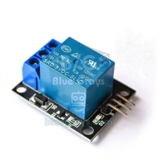
Relays, motors, solenoid locks and valves are all coils. When you drive them with a transistor or MOSFET, the moment you cut the current the coil reverses its voltage to keep the current flowing and produces a high spike, as in the example above. This is called back EMF (back electromotive force) or inductive kickback. The fix is very simple: connect a diode across the coil in reverse. The diode's cathode (the striped end) goes to the coil's + terminal and the anode to the end connected to the transistor. While the coil operates normally the diode is reverse-biased and does nothing; when the current is cut, the coil's current circulates through the diode and the energy dies away harmlessly.
| Load | Recommended protection | Note |
|---|---|---|
| 5 V or 12 V relay | 1N4007 or 1N4148 diode | Already on the board of ready-made relay modules |
| Small DC motor | 1N5819 Schottky diode and a 100 nF capacitor | The capacitor also reduces brush noise |
| Solenoid lock or valve | 1N4007 or the stronger 1N5408 | For large currents the diode must handle a large current too |
| Motor with an L298N | The module's built-in diodes | A bare L298 chip needs external diodes |
| Motor with an L293D | Protection diodes inside the chip | The L293 (without the D) has no diodes |
The diode has a small side effect: because the coil's energy dies away slowly, the relay contact releases a little later. In most projects you won't notice; where very fast release is needed, a zener is added in series with the diode. For diode types and the correct direction see what is a diode; for driving a relay with a transistor see what is a transistor and what is a relay module. Connecting a coil directly to an Arduino pin both exceeds the pin's current limit and can destroy the microcontroller with back EMF; always put a transistor or a MOSFET in between.
Estimating inductance from the number of turns
If you want to wind your own coil, you can estimate its inductance by calculation. For a single-layer air-core coil, the centimetre version of Wheeler's formula is handy: L (µH) = r² × N² / (22.9 × r + 25.4 × l). Here r is the coil's radius, l the length of the winding (both in cm) and N the number of turns. For example, if you wind 50 turns over 3 cm on a tube 2 cm in diameter (1 cm radius): L = 1 × 2500 / (22.9 + 76.2) ≈ 25 µH.
With ring (toroid) cores the calculation is even easier, because the manufacturer gives the core's AL value: L = AL × N². AL is usually given in nH/turn². Wind 20 turns on a ring with AL = 50 nH/turn² and L = 50 × 400 = 20,000 nH = 20 µH. If you need a specific value, invert the formula: N = √(L / AL). The calculation is always approximate; how tightly the turns sit and the wire thickness change the value by a few percent, so measuring the finished coil is best.
| Change | Effect on inductance |
|---|---|
| Doubling the number of turns | Quadruples it (N²) |
| Increasing the radius | Increases it |
| Spreading the same turns over a longer length | Decreases it |
| Adding a ferrite or iron powder core | Increases it tens or hundreds of times |
| Removing the core or leaving a gap | Decreases it, but raises the saturation current |
Measuring an inductor with an Arduino: the LC resonance method
Most multimeters can't measure inductance, but with an Arduino Uno, an LM339 comparator and a few parts you can build a handy inductance meter. The idea: connect the coil in parallel with a known capacitor, feed it current briefly so it stores energy, and then cut the current. The circuit oscillates at its resonant frequency; the LM339 turns the oscillation into a square wave, and the Arduino measures the half period with pulseIn() and works back to the inductance from f = 1 / (2π√(LC)).
- Connect the Arduino's D13 pin to the top of the LC circuit through a 220 Ω resistor and a 1N4148 diode.
- Connect the coil under test and a 2 µF film capacitor (two 1 µF in parallel) side by side between that top node and GND.
- Connect the top of the LC circuit to the LM339's + input through a 1 kΩ resistor, and its − input to GND.
- Power the LM339 from 5V and GND, connect its output to D11 and add a 1 kΩ pull-up resistor from the output to 5V.
- Upload the code, open the Serial Monitor at 115200 baud and watch the reading.
1// LC rezonansıyla bobin ölçer / LC resonance inductance meter
2// D13 -> 220 Ω -> 1N4148 -> LC (bobin ve kondansatör paralel) -> LM339 (+) giriş
3// D13 -> 220 Ω -> 1N4148 -> LC tank (coil and capacitor in parallel) -> LM339 (+) input
4// LM339 (-) GND'ye, çıkış D11'e ve 1 kΩ ile 5V'a / LM339 (-) to GND, output to D11 with 1 kΩ to 5V
5
6const int DRIVE_PIN = 13;              // LC devresini şarj eden pin / pin that charges the tank
7const int SENSE_PIN = 11;              // karşılaştırıcı çıkışı / comparator output
8const double C_FARAD = 2.0e-6;         // kondansatörün gerçek değeri (2 µF) / real capacitor value (2 µF)
9
10void setup() {
11  Serial.begin(115200);
12  pinMode(DRIVE_PIN, OUTPUT);
13  pinMode(SENSE_PIN, INPUT);
14}
15
16void loop() {
17  digitalWrite(DRIVE_PIN, HIGH);
18  delay(5);                            // bobinden akım geçsin, enerji depolansın / let current build up in the coil
19  digitalWrite(DRIVE_PIN, LOW);        // akımı kes: LC salınmaya başlar / cut the current: the tank starts ringing
20  delayMicroseconds(100);
21
22  unsigned long halfPeriod = pulseIn(SENSE_PIN, HIGH, 5000);   // yarım periyot (µs), 0 = zaman aşımı / half period (µs), 0 = timeout
23  if (halfPeriod > 0) {
24    double f = 1.0e6 / (2.0 * halfPeriod);                      // frekans (Hz) / frequency (Hz)
25    double L = 1.0 / (4.0 * PI * PI * f * f * C_FARAD);         // f = 1 / (2π√(LC)) formülünden / from f = 1 / (2π√(LC))
26    Serial.print("f = ");
27    Serial.print(f, 0);
28    Serial.print(" Hz   L = ");
29    Serial.print(L * 1.0e6, 1);                                 // µH cinsinden / in µH
30    Serial.println(" uH");
31  } else {
32    Serial.println("Salinim yok / no oscillation");
33  }
34  delay(500);
35}
The accuracy depends largely on the capacitor: C appears directly in the formula, so measure the capacitor's real value with a multimeter and write it into the C_FARAD line of the code. Ceramic capacitors change value with voltage and temperature, so a film capacitor is better. With 2 µF a 100 µH coil rings at about 11 kHz and the half period is 44 µs. This setup gives good results from about 50 µH to a few tens of mH; with very small coils the frequency rises and precision drops. On the Pico you can build the same circuit by pulling the LM339 output up to 3V3. In MicroPython you use time_pulse_us() instead of pulseIn():
1from machine import Pin, time_pulse_us
2import math
3import time
4
5drive = Pin(15, Pin.OUT)               # 330 Ω ve diyot üzerinden LC'ye / to the tank through 330 Ω and a diode
6sense = Pin(14, Pin.IN)                # LM339 çıkışı, 3V3'e 1 kΩ / LM339 output, 1 kΩ pull-up to 3V3
7C_FARAD = 2.0e-6                       # kondansatör değeri / capacitor value
8
9while True:
10    drive.value(1)
11    time.sleep_ms(5)                   # bobin akımı otursun / let the coil current settle
12    drive.value(0)                     # salınımı başlat / start the ringing
13    half = time_pulse_us(sense, 0, 5000)   # ilk LOW yarım periyot (µs), eksi = zaman aşımı / first LOW half period (µs), negative = timeout
14    if half > 0:
15        f = 1e6 / (2 * half)
16        L = 1 / (4 * math.pi ** 2 * f ** 2 * C_FARAD)
17        print("f = %d Hz  L = %.1f uH" % (int(f), L * 1e6))
18    else:
19        print("Salinim yok / no oscillation")
20    time.sleep_ms(500)
Values to check when choosing an inductor
| Value | Meaning | Why it matters |
|---|---|---|
| Inductance (L) | Value in µH or mH | Must match what the circuit needs |
| Tolerance | How far the value may deviate (±10%, ±20%) | Important in filters and resonant circuits |
| Saturation current (Isat) | Current at which inductance drops noticeably | The peak current must stay below it |
| Rated current (Irms) | Current it can carry without overheating | The average current must stay below it |
| DC resistance (DCR) | Resistance of the wire | Lower means less heat and loss |
| Self-resonant frequency (SRF) | Frequency at which the inductor starts acting like a capacitor | The operating frequency must be far below it |
| Shielded or unshielded | Whether the magnetic field leaks outside | A shielded inductor disturbs nearby circuits less |
Common mistakes and fixes
- Driving a relay without a diode: The transistor dies after a few switching cycles or the Arduino resets at random. Connect a reverse diode across the coil.
- Replacing an inductor by inductance alone: A smaller part with the same µH value saturates and overheats in a buck module; check the saturation current too.
- Misreading SMD codes: Thinking 330 means 330 µH; it's actually 33 µH. Use the inductor code tool to be sure.
- Reading colour codes as ohms: On an axial inductor the result is in µH; brown-black-brown is 100 µH, not 100 Ω.
- Placing inductors side by side: Two unshielded inductors affect each other's fields; mount them at right angles or use shielded types.
- Ignoring a whining module: A faint whine from a buck module usually means the inductor is overloaded or saturating; reduce the load or use a stronger module.
At first glance an inductor looks like an ordinary coil of wire, but it's a versatile component that smooths current, carries energy and filters noise. If you remember that inductance resists changes in current, and that this can be both useful and dangerous, you'll build your relay, motor and power supply projects much more safely. In the BlueGrays app you'll find projects for switching a 220 V lamp with a relay, buzzers, stepper motors and motor control with the L298N, with step-by-step circuit diagrams and code, and you can read values quickly with the inductor code and colour code tools in the Tools tab.
Frequently asked questions
What does an inductor do?
An inductor resists sudden changes in current and stores energy in a magnetic field. This lets it carry energy in step-down and step-up modules, filter high-frequency noise, select frequencies together with a capacitor in radios, and produce motion as an electromagnet in relays and motors.
What is the difference between an inductor and a capacitor?
An inductor stores energy in a magnetic field and resists changes in current; a capacitor stores energy in an electric field and resists changes in voltage. With DC an inductor acts like a short circuit and a capacitor like an open circuit. As frequency rises, an inductor's resistance increases while a capacitor's decreases.
What is the unit of inductance?
An inductor's value is its inductance, measured in henries (H). Electronics mostly uses millihenries (mH), microhenries (µH) and nanohenries (nH). 1 mH equals 1000 µH and 1 µH equals 1000 nH.
What does 101 mean on an SMD inductor?
The code 101 means the first two digits, 10, followed by one zero, and the value is in microhenries: 101 = 100 µH. Likewise 100 = 10 µH, 220 = 22 µH, 4R7 = 4.7 µH and 47N = 47 nH.
Why is a diode connected across a relay coil?
When the current in a relay coil is cut, the coil produces a high reverse voltage (back EMF), and this spike can destroy the transistor or Arduino driving the relay. A diode connected across the coil in reverse gives this current a safe path and dissipates the energy harmlessly. Ready-made relay modules already have this diode on the board.
How do you test an inductor with a multimeter?
On the resistance range, a healthy inductor reads a few ohms or less; if you see OL, the wire is broken. To measure inductance you need an LCR meter or a multimeter with an inductance range. If you don't have one, you can find an approximate value with an Arduino, an LM339 and a known capacitor using the LC resonance method.
Projects to build after reading this
See all projects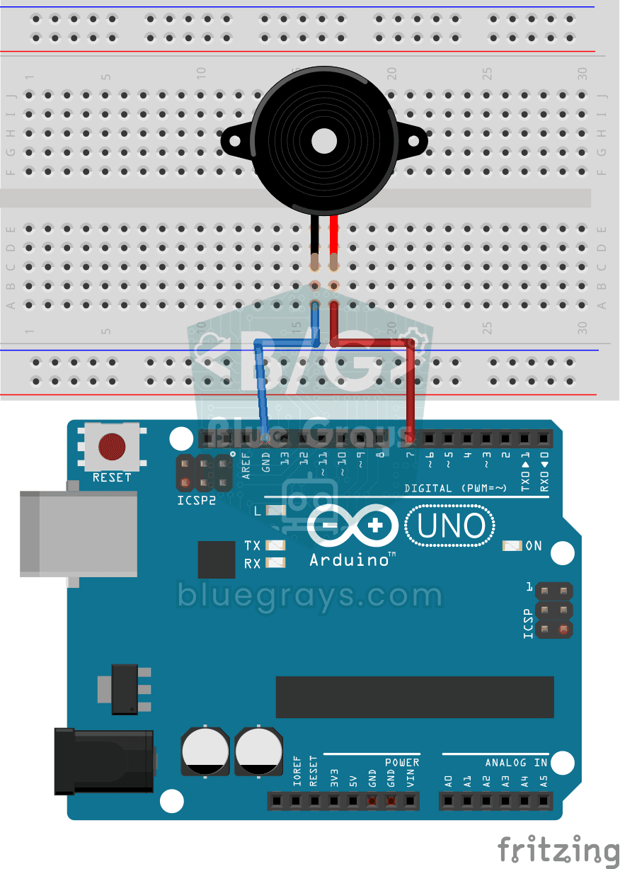
Using a Buzzer
Ever wondered how a doorbell or an alarm makes its sound? The Arduino makes a small buzzer beep at short intervals: beep, pause, beep, pause.

LED Blink
The very first hello of electronics: switching a single LED on and off. The Arduino turns the LED on and off at short intervals, so the light blinks quickly.
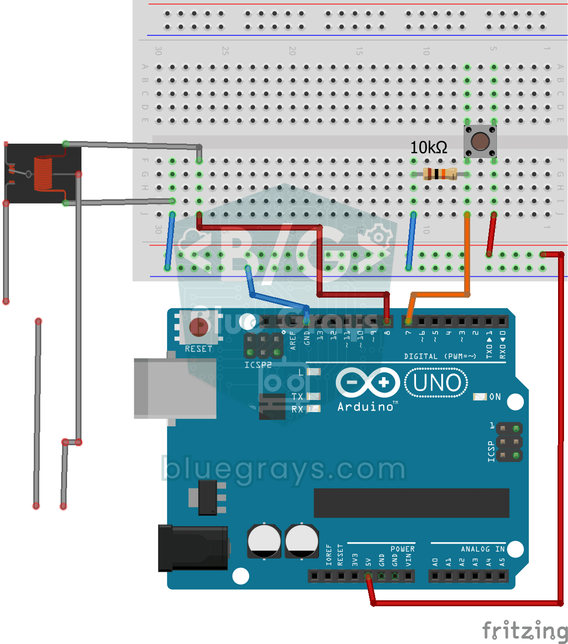
Lighting 220V Bulb with Push Button
As long as you hold the button, a real 220-volt bulb stays lit, and it goes out the moment you let go.
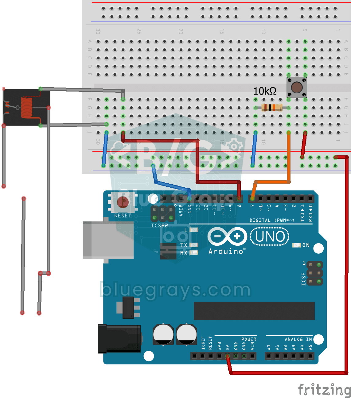
Lighting 220V Bulb with Button (On-Off)
Want to switch a real household bulb on and off with a tiny button? Each time you press the button, the Arduino flips a relay and the bulb lights up; press again and it goes off.
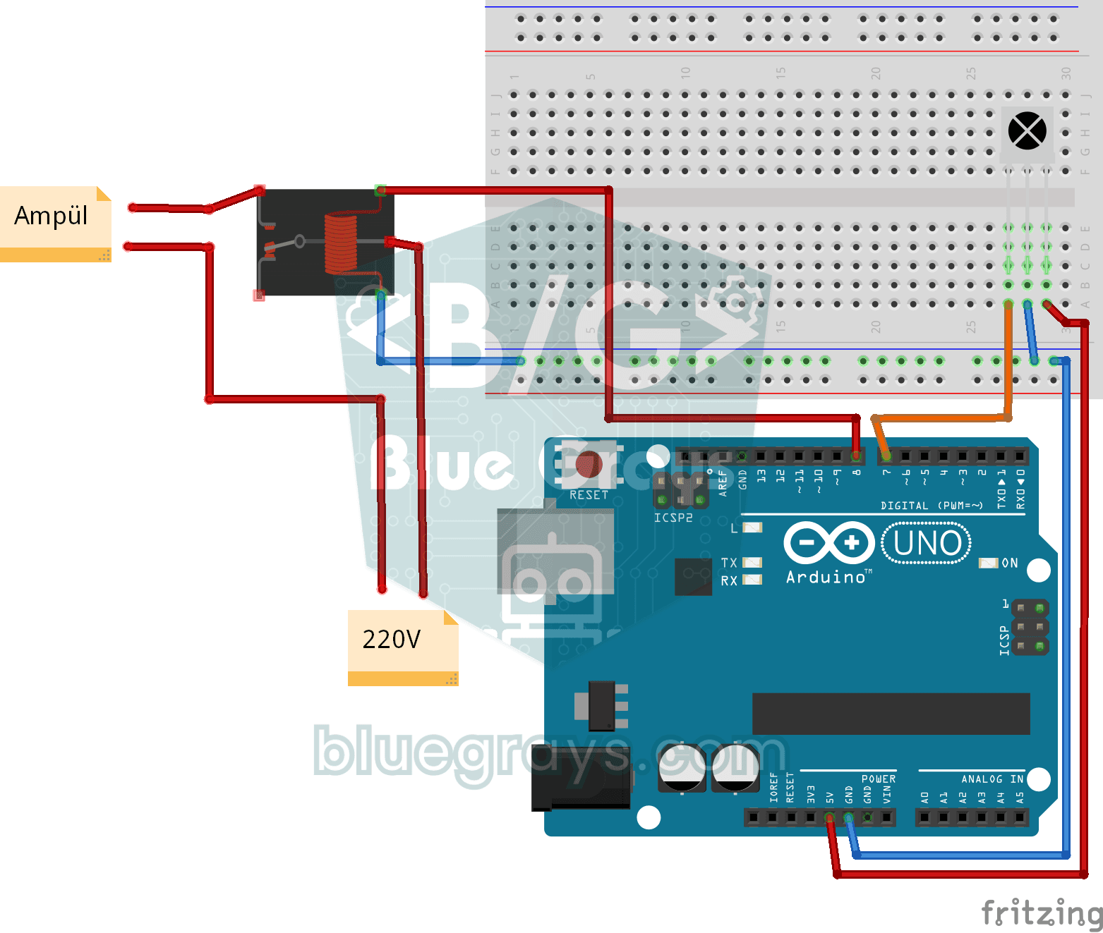
Lighting 220V Bulb with Remote Control
Switch a real light bulb in your home on and off with a TV remote, without getting up from the sofa.
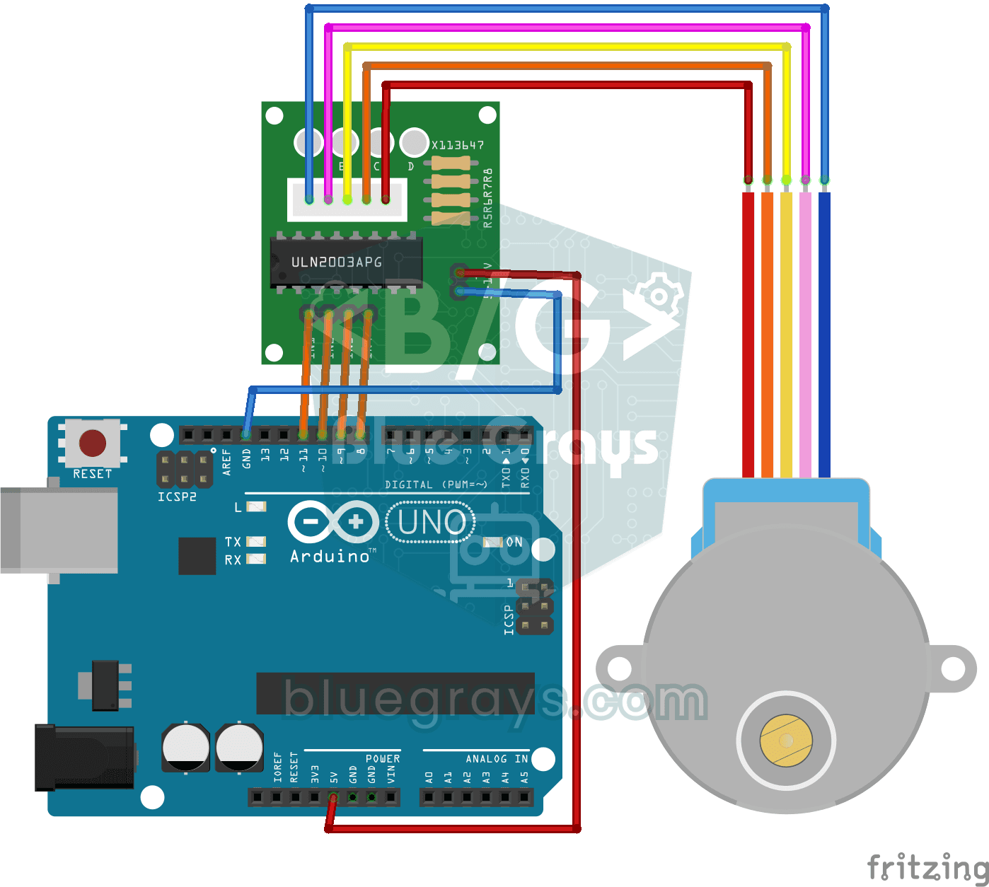
Using a Stepper Motor
A motor that turns step by step, exactly as far as you want, like the hand of a clock.

Bluetooth Controlled Car with L298N
Turn your phone into a remote and drive your own robot car. The Arduino receives commands from a remote-control app on your phone through a Bluetooth module and spins the wheels with a motor driver…

Obstacle Avoidance Robot
How about building a smart vehicle that finds its own way? The Obstacle Avoidance Robot constantly scans its surroundings thanks to the ultrasonic sensor in front of it.