
How to Adjust an LM2596 Buck Converter to 5 V or 3.3 V
How to adjust an LM2596 buck converter: set 5 V or 3.3 V with the trimpot and a multimeter, power Arduino and servos from 12 V, plus heat, current and the 7805.
Adjusting an LM2596 means feeding power into the module and turning the brass screw of the blue trimpot while you measure the output with a multimeter, until it reads the voltage you want, for example 5 V or 3.3 V. The LM2596 step-down (buck) module is a cheap and very common voltage regulator that efficiently turns a 12 V adapter, a car battery or a 2S Li-ion pack into a lower voltage for Arduino, ESP32, servos and LED strips. It takes 4.5–40 V in, brings it down to anything between about 1.25 V and 35 V, and can deliver up to 3 A. The golden rule fits in one sentence: always set and measure the output before you connect a load.
In this guide you will learn how a buck converter works, the module's pins and parts, how to set 5 V and 3.3 V step by step with the trimpot and a multimeter, and the Vout = 1.23 × (1 + R2 / R1) formula that sets the output. Then we will look at powering Arduino and servos from 12 V, current limit and heat, efficiency and the difference from a 7805, and common mistakes (reverse polarity, voltage drop under load), before moving on to code that measures the output with Arduino, ESP32 and Raspberry Pi Pico.
What is the LM2596 and how does it work?
The LM2596 is a switching step-down regulator IC, originally developed by National Semiconductor and made today by Texas Instruments. Linear regulators such as the 7805 get rid of excess voltage by turning it into heat; the LM2596 instead switches its internal power transistor on and off about 150,000 times a second (150 kHz). While the transistor is on, current flows through the inductor to the load and the inductor stores energy in its magnetic field; when the transistor turns off, the inductor keeps supplying that energy to the load through a Schottky diode. The output capacitor smooths out these pulses. The fraction of time the transistor stays on is called the duty cycle, roughly D ≈ Vout / Vin: to get 5 V from 12 V, the switch is on about 42% of the time.
Because no energy is burned off, efficiency is around 80–90% and the current drawn from the input is lower than the current delivered at the output: a module supplying 2 A at 5 V from 12 V draws only about 1 A from the input. The FB (feedback) pin keeps the output voltage steady. The chip compares the voltage on FB with its internal 1.23 V reference and adjusts the duty cycle accordingly. On the ready-made module, one leg of the voltage divider feeding the FB pin is a multi-turn trimpot; turning the screw changes the divider ratio and therefore the output voltage. There are also fixed 3.3 V, 5 V and 12 V versions of the LM2596, but in the Arduino world the most common one is the blue module built with the adjustable (ADJ) version.
| Feature | LM2596 chip (datasheet) | Ready-made module (typical) |
|---|---|---|
| Input voltage | 4.5–40 V (absolute maximum 45 V) | 4.5–40 V; at least 1.5–2 V above the output |
| Output voltage | ADJ: 1.23–37 V; fixed: 3.3 / 5 / 12 V | About 1.25–35 V with the trimpot |
| Output current | 3 A | About 2 A continuous without a heatsink, 3 A with one |
| Switching frequency | 150 kHz (127–173 kHz) | 150 kHz |
| Feedback reference | 1.23 V | 1.23 V |
| Efficiency | 73–90% (depending on voltage and current) | Typically 80–88% for 12 V → 5 V |
| Quiescent current | Typ. 5 mA, max. 10 mA; 80 µA when switched off via ON/OFF | 5–10 mA + power LED (if fitted) |
| Current limit | Typ. 4.5 A peak (3.6–6.9 A) | Not adjustable (only CC/CV versions have a setting) |
| Protection | Current limiting and thermal shutdown | No reverse polarity protection |
Module pins and on-board parts
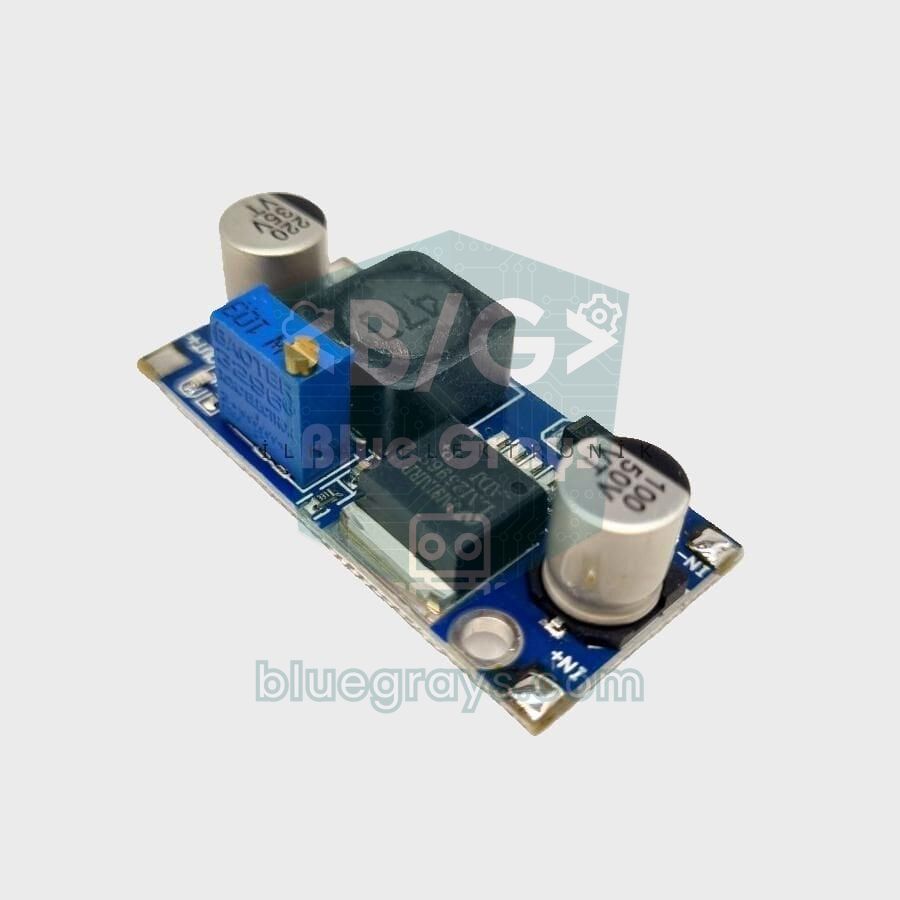
The blue LM2596 module has four connection points: IN+ and IN− are the input, OUT+ and OUT− the output. IN− and OUT− are connected together on the board; a buck converter does not isolate input from output, so the source, the module and the board you power share a common GND. On the board you'll find the five-pin LM2596S chip (TO-263 package: VIN, output, GND, FB and ON/OFF), a large 33–47 µH inductor usually marked 330 or 470, a 3 A Schottky diode such as the SS34, an electrolytic capacitor on the input and one on the output (usually 100–220 µF), and a multi-turn trimpot marked 103 (10 kΩ). You can decode the marking on the inductor with the inductor code calculator. On most modules the chip's ON/OFF pin is tied to GND, so the module starts working as soon as power is applied.
| Module pin | Function | Connects to |
|---|---|---|
| IN+ | Input positive (4.5–40 V) | Positive of the adapter, battery or battery pack |
| IN− | Input negative (GND) | Negative of the source |
| OUT+ | Regulated output positive | Arduino 5V or Vin, ESP32 5V, Pico VSYS, the servo's red wire |
| OUT− | Output negative (same GND as IN−) | The board's GND, the servo's brown or black wire |
How to adjust the LM2596 step by step: 5 V or 3.3 V with a multimeter
- Don't connect anything to the output. The module is adjusted with no load; you only connect the Arduino or ESP32 after you've seen the correct voltage.
- Connect the real source you'll use in the project (for example a 12 V 2 A adapter) to the input: positive to IN+, negative to IN−. If the board has an LED, it lights up.
- Set the multimeter to DC voltage (20 V range or auto); touch the red probe to OUT+ and the black probe to OUT−. The first reading may be close to the input voltage, because the factory setting is unknown.
- With a small flat screwdriver, turn the trimpot's brass screw 2–3 turns in one direction and watch the display. If the voltage goes down you're turning the right way; if it goes up, turn the other way. The direction can differ from module to module, depending on how the trimpot is wired.
- On a multi-turn trimpot of about 25 turns, sweeping the full range can take 20 turns or more. There is no end stop on the screw; at the end it slips with a faint click and the voltage stops changing. If that happens, turn back the other way.
- As you get close to the target, continue in quarter turns and then even smaller steps. For 5 V, leave it between 5.00–5.10 V; for 3.3 V, between 3.30–3.35 V. On 3.3 V boards such as the ESP32 and Pico, never exceed 3.6 V.
- Connect the load, or test with a 10 Ω / 5 W resistor that draws about 500 mA at 5 V, and repeat the measurement under load. If the voltage drops by more than 0.1–0.2 V, check the source and the wiring.
- When you're done, put a drop of nail polish or hot glue on the trimpot screw; on vibrating robots the setting can drift over time.
The output formula: Vout = 1.23 × (1 + R2 / R1)
The LM2596 adjusts its output so that the voltage on the FB pin is 1.23 V. If we call the resistor between the output and FB R2, and the one between FB and GND R1, the output is Vout = 1.23 × (1 + R2 / R1). On the module the 10 kΩ trimpot takes the place of R2, while R1 is a small fixed resistor on the board. Two important consequences follow from the formula: even with R2 close to zero, the output can't go below 1.23 V; and however large R2 gets, the output can't exceed the input. If you turn the trimpot too far up, the chip keeps the switch permanently on and the output gets stuck about 1–2 V below the input. This is the most common cause of the "my module doesn't step down" complaint.
If you want fixed resistors instead of the trimpot in a vibrating or long-lived project, follow the datasheet and choose R1 between 240 Ω and 1.5 kΩ. With R1 = 1 kΩ, for 5 V you get R2 = 1 kΩ × (5 / 1.23 − 1) ≈ 3.07 kΩ; with a 1% 3.09 kΩ resistor the output is 5.03 V. For 3.3 V, R2 ≈ 1.68 kΩ, and a 1% 1.69 kΩ gives 3.31 V. This is really just a voltage divider; you can check the ratios with the voltage divider calculator.
| Target output | Recommended minimum input | Typical use |
|---|---|---|
| 3.3 V | 5 V | The 3V3 pin of an ESP32 or Pico, 3.3 V sensors |
| 4.0–4.1 V | 6 V | SIM800L GSM module |
| 5.0 V | 7 V | Arduino 5V pin, ESP32 5V pin, SG90 servos, WS2812B LEDs |
| 6.0 V | 8 V | MG996R servos (upper limit for SG90 and MG90S) |
| 7.5–9 V | 10–11 V | Arduino DC jack or Vin pin |
| 12 V | 14–15 V | 12 V fans, relays and LED strips from a 24 V system |
The minimum input values in the table are for a 2–3 A load: the LM2596's switch drops a typical 1.16 V at 3 A, and the inductor and wiring add a few hundred millivolts. At light load (around 1 A) the difference falls to about 1.5 V. A 7.4 V 2S Li-ion pack drops to around 6.4 V as it discharges; that's still enough for a 1 A 5 V rail, but not for a 6 V servo rail. For setting up a GSM module that needs 4 V, see the SIM800L article.
Powering an Arduino from a 12 V adapter or battery
There are two correct ways to power an Arduino with an LM2596. The first is to set the module to 5.0 V and connect the output straight to the 5V pin. Because this bypasses the board's own regulator, it produces almost no heat and is the most efficient option; but nothing is left to protect the board. If the trimpot drifts or the module fails and passes the input to the output, 12 V goes straight into the microcontroller. If you also plug in the USB cable with this connection, the computer's USB supply and the module's output are tied together; disconnecting the module while uploading code is the safest approach.
The second way is to set the module to 7.5–9 V and connect it to the DC jack or the Vin pin. The board's regulator then does the final regulation, and the diode on the jack input protects against reverse polarity. Feeding 12 V straight into the jack also works, but with a 200 mA load the board's small regulator produces (12 − 5) × 0.2 = 1.4 W of heat; set the LM2596 to 7.5 V and that loss falls to (7.5 − 5) × 0.2 = 0.5 W. You'll find every power option in the Arduino power supply article and the pin locations in Arduino Uno pinout.
| Connection | LM2596 setting | Advantage | Watch out |
|---|---|---|---|
| Arduino 5V pin | 5.0–5.1 V | Coolest and most efficient option | No protection; don't plug in USB at the same time |
| Arduino DC jack | 7.5–9 V | Reverse polarity diode and the board's regulator protect it | The diode drops about 0.7 V |
| Arduino Vin pin | 7.5–9 V | No jack needed, the board's regulator protects it | No reverse polarity protection |
| ESP32 5V (VIN) pin | 5.0 V | The on-board LDO produces 3.3 V | Never feed 5 V into the 3V3 pin |
| ESP32 3V3 pin | 3.30 V | Bypasses the board's regulator | Above 3.6 V the ESP32 can be damaged |
| Pico VSYS pin | 5.0 V | VSYS accepts 1.8–5.5 V | Add a Schottky diode if USB is also connected |
Powering servos and motors: working out the current
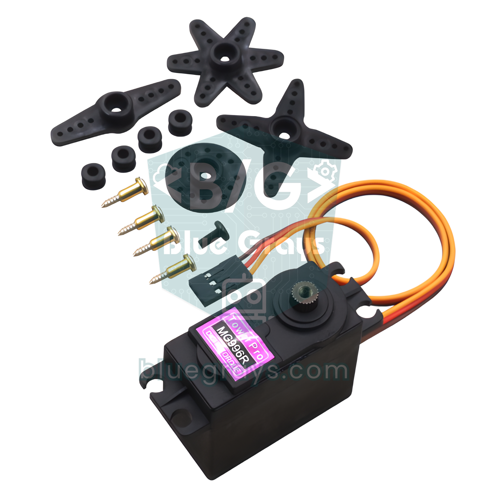
The most common use of the LM2596 is a servo supply. An SG90 draws 100–250 mA while moving and jumps to 600–700 mA at start-up and under load. An MG996R reaches around 2.5 A when stalled at 6 V. When choosing a module, don't count the average: add up the current of all the servos that could be loaded at the same time. Expecting 2 A continuous from an LM2596 without a heatsink is realistic: 3 SG90s run comfortably, but powering a robot arm with 4–6 MG996Rs from a single module is asking for resets and jitter. In that case use a separate module for every one or two servos, or a 5 A module such as the XL4015.
You should also work out the input current, because if the adapter can't keep up, the output drops however good the module is. The formula is Iin = (Vout × Iout) / (Vin × η). For 2 A at 5 V from 12 V at 85% efficiency, Iin = 10 W / (12 V × 0.85) ≈ 0.98 A, so a 12 V 2 A adapter is enough. The same load draws about 1.6 A from a 7.4 V 2S battery pack. Placing a 470–1000 µF electrolytic capacitor next to the servo rail lets the capacitor, rather than the module, supply the start-up currents. For every fix for servo-related resets see Arduino keeps resetting, and for wiring servos see what is a servo motor and MG996R servo.
Current limit, heat and heatsinks
A buck converter is efficient, but not lossless. The power lost is roughly Ploss = Pout × (1/η − 1) and is shared between the chip, the Schottky diode and the inductor. At a 5 V 2 A (10 W) output with 85% efficiency, about 1.8 W of heat is produced. The LM2596S on the module is a TO-263 package soldered to a small copper area; according to the datasheet, its thermal resistance to air is 30–50 °C/W depending on the copper area. That's why at 2 A the chip gets too hot to keep your finger on, and at 3 A a small stick-on aluminium heatsink and airflow are a must. Inside a closed box these limits drop even further.
| Load (12 V → 5 V) | Output power | Estimated loss | Condition |
|---|---|---|---|
| 0.5 A | 2.5 W | ~0.4 W | Warm, no heatsink needed |
| 1 A | 5 W | ~0.8 W | Hot but comfortable |
| 2 A | 10 W | ~1.8 W | Very hot, needs airflow |
| 3 A | 15 W | ~3.5 W | Heatsink and fan required |
The LM2596's current limit can't be adjusted by the user. When the peak switch current reaches about 4.5 A (3.6–6.9 A depending on production spread), the chip cuts the pulses short, lowers the frequency under overload and shuts itself down if it overheats. These protections usually save the module during a short circuit, but they're no substitute for a fuse. For jobs where you need to set the current, such as driving a power LED or building a current-limited test supply, there are CC/CV (constant current / constant voltage) LM2596 modules with a second trimpot for the current. If you want a rail that's robust against short circuits, add a suitably rated fuse on the input as well.
Efficiency and comparison with the 7805
Compared with the 7805 voltage regulator, which does the same job, the size of the difference becomes clear. Delivering 1 A at 5 V from 12 V, the 7805 also draws 1 A from the input and turns (12 − 5) × 1 = 7 W into heat; its efficiency is only 42% and it needs a large heatsink. The LM2596 draws about 0.49 A from the input for the same load and loses less than 1 W. In battery-powered projects this difference translates directly into runtime: when efficiency doubles, the battery lasts roughly twice as long.
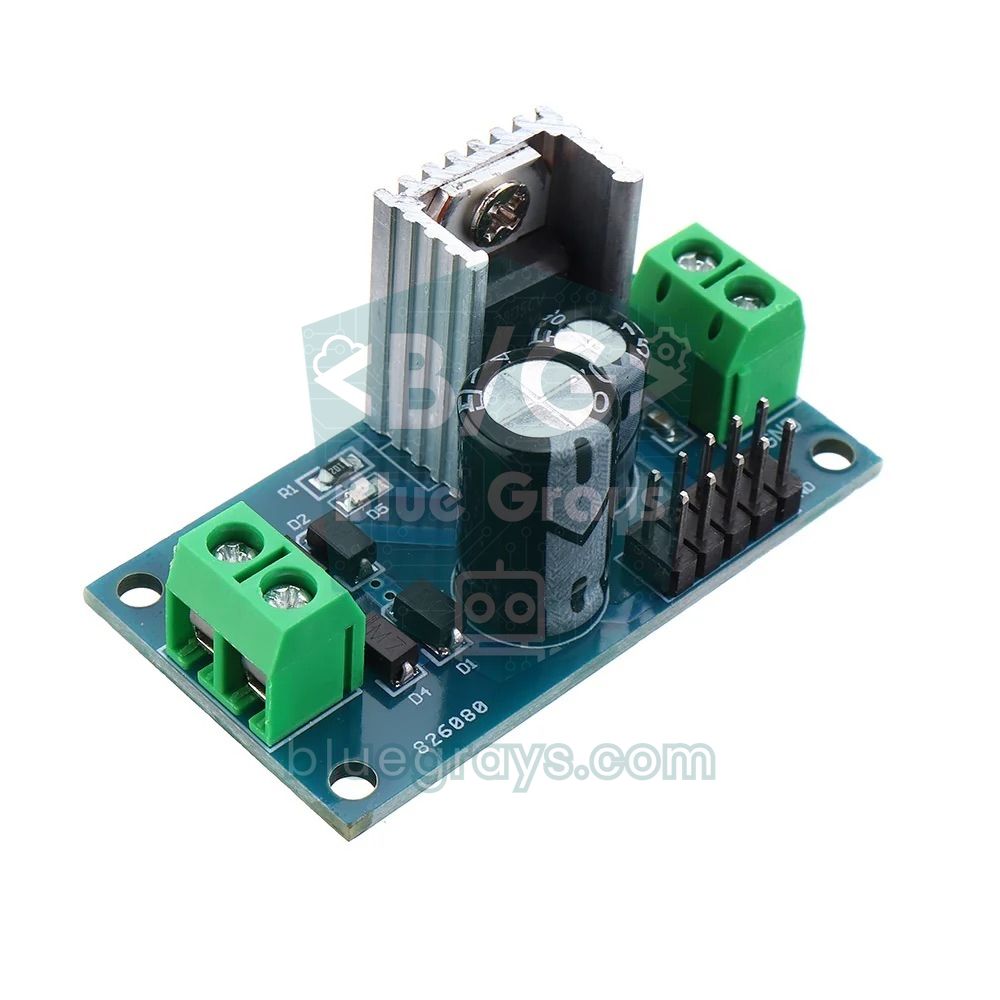
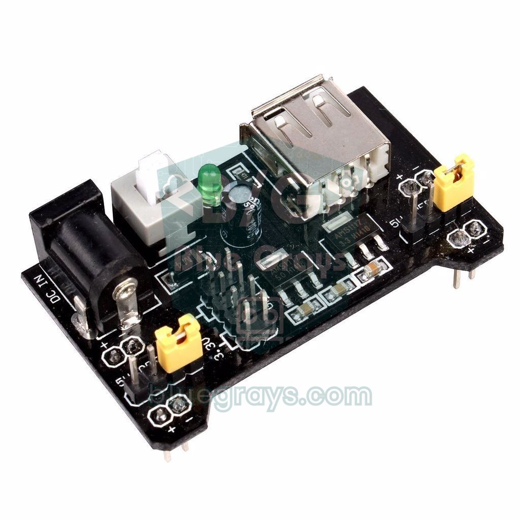
The price of a buck converter is noise. According to the datasheet, the sawtooth ripple on the output is typically 0.5–3% of the output voltage, i.e. 25–150 mV at 5 V, plus 150 kHz switching noise on top. That's no problem for Arduino, servos, relays and LEDs, but it shows up when you power precise analog measurements, a microphone or an audio amplifier. In those cases combine the two: first step down to 7–8 V with the LM2596, then get a clean 5 V with a 7805 or an LDO, so you gain both efficiency and quiet. For small low-current experiments on a breadboard, a ready-made MB102 breadboard power module is a handy option.
| Feature | LM2596 (buck) | 7805 (linear) | AMS1117-3.3 (LDO) |
|---|---|---|---|
| How it works | 150 kHz switching, energy stored in an inductor | Turns excess voltage into heat | Turns excess voltage into heat |
| Efficiency from 12 V | 80–90% | ~42% at 5 V out | ~27% at 3.3 V out (input max. 15 V) |
| Maximum current | 3 A (2 A continuous in practice) | 1–1.5 A | 0.8–1 A |
| Minimum input-output difference | ~1.5–2 V | ~2 V | ~1.1–1.3 V |
| Output noise | Tens of mV of ripple | Very low | Very low |
| Output setting | 1.25–35 V with the trimpot | Fixed 5 V | Fixed 3.3 V |
| Quiescent current | 5–10 mA | 3–8 mA | ~5 mA |
| Best at | Large voltage difference, high current, batteries | Small difference, low current, quiet supply | 3.3 V from 5 V, a few hundred mA |
Measuring the LM2596 output under load with Arduino
The best way to see how much the voltage drops under load is to measure the drop while the load is running. The code below sweeps a servo continuously between 0 and 180 degrees and prints the lowest and highest voltage seen at the LM2596 output to the Serial Monitor. Here's the wiring: the servo's red wire goes to OUT+, the brown wire to OUT− and the signal wire to D9; between OUT+ and GND you build a 47 kΩ and 10 kΩ voltage divider and connect its midpoint to A0. The Arduino is powered over USB, and OUT− must be joined to the Arduino's GND.
1// LM2596 yük testi: servo dönerken çıkış gerilimini izle / LM2596 load test: watch the output while a servo moves
2// Kart: Arduino Uno / Nano (ATmega328P) / Board: Arduino Uno / Nano (ATmega328P)
3#include <Servo.h>
4
5const int SENSE_PIN = A0;          // OUT+ -> 47k -> A0 -> 10k -> GND
6const int SERVO_PIN = 9;           // servo sinyal kablosu / servo signal wire
7const float R_TOP = 47000.0;       // bölücü üst direnç / divider top resistor
8const float R_BOTTOM = 10000.0;    // bölücü alt direnç / divider bottom resistor
9const float AREF_V = 1.1;          // dahili referans, multimetreyle düzelt / internal reference, calibrate with a multimeter
10const float LOW_LIMIT = 4.6;       // 5 V hat için uyarı sınırı / warning limit for a 5 V rail
11
12Servo servo;
13float vMin, vMax;
14
15float readOutput() {
16  long sum = 0;
17  for (int i = 0; i < 8; i++) {
18    sum += analogRead(SENSE_PIN);  // 8 örneğin toplamı / sum of 8 samples
19  }
20  float vPin = (sum / 8.0) * AREF_V / 1023.0;
21  return vPin * (R_TOP + R_BOTTOM) / R_BOTTOM;  // bölücüyü geri hesapla / undo the divider
22}
23
24void track() {
25  float v = readOutput();
26  if (v < vMin) vMin = v;          // en düşük değer / lowest value
27  if (v > vMax) vMax = v;          // en yüksek değer / highest value
28}
29
30void setup() {
31  Serial.begin(9600);
32  analogReference(INTERNAL);       // 1,1 V referans, beslemeden bağımsız / 1.1 V reference, independent of the supply
33  for (int i = 0; i < 10; i++) {   // referans otursun, ilk okumaları at / let the reference settle, drop first readings
34    analogRead(SENSE_PIN);
35    delay(5);
36  }
37  servo.attach(SERVO_PIN);
38}
39
40void loop() {
41  vMin = 99.0;
42  vMax = 0.0;
43  for (int a = 0; a <= 180; a += 2) {     // 0 -> 180 derece / 0 -> 180 degrees
44    servo.write(a);
45    for (int k = 0; k < 5; k++) { track(); delay(2); }
46  }
47  for (int a = 180; a >= 0; a -= 2) {     // 180 -> 0 derece / 180 -> 0 degrees
48    servo.write(a);
49    for (int k = 0; k < 5; k++) { track(); delay(2); }
50  }
51  Serial.print(F("Min: "));
52  Serial.print(vMin, 2);
53  Serial.print(F(" V  Max: "));
54  Serial.print(vMax, 2);
55  Serial.print(F(" V  Dusus / Drop: "));
56  Serial.print(vMax - vMin, 2);
57  Serial.println(F(" V"));
58  if (vMin < LOW_LIMIT) {
59    Serial.println(F("UYARI: gerilim cok dusuyor / WARNING: voltage sags too much"));
60  }
61  delay(1000);
62}
Instead of the Arduino's own supply voltage, the code uses the ATmega328P's internal 1.1 V reference (analogReference(INTERNAL)), so the reading isn't affected by USB being 4.7 V or 5.1 V. The highest voltage you can measure with the 47k/10k divider is about 6.2 V; on a 6 V servo rail, allow for the reference tolerance by making the top resistor 56 kΩ and changing the R_TOP constant. Because the internal reference can vary by about ±10% from chip to chip, measure the output once with a multimeter and adjust AREF_V (e.g. 1.08) until the two results match. If the drop exceeds 0.3 V while the servo moves, shorten the wires, use thicker wire and add 470 µF to the servo rail; below 0.1 V your supply is healthy.
ESP32: running from a 12 V battery and monitoring it
Powering an ESP32 from a 12 V battery is a common scenario for a garden sensor station or an in-car tracker. Set the LM2596 to 5.0 V and connect it to the ESP32 board's 5V (VIN) pin; the board's own LDO produces 3.3 V. The LM2596 easily covers the short current bursts the ESP32 draws when transmitting over Wi-Fi; you'll find the symptoms of a weak supply in detail in the ESP32 brownout error article. The code below reads the battery voltage on GPIO34 through a 100 kΩ / 22 kΩ divider and puts the ESP32 into deep sleep for 10 minutes once the voltage reaches the safe lower limit of a lead-acid battery.
1// ESP32: LM2596 ile 12 V aküden beslen, aküyü izle / ESP32: run from a 12 V battery via an LM2596, monitor the battery
2#include <Arduino.h>
3#include "esp_sleep.h"
4
5const int BAT_PIN = 34;                           // GPIO34: yalnız giriş, ADC1 / input-only, ADC1
6const float RATIO = (100.0 + 22.0) / 22.0;        // 100k / 22k bölücü (~5,55) / divider (~5.55)
7const float LOW_V = 11.8;                         // kurşun asit akü alt sınırı / lead-acid low limit
8const uint64_t SLEEP_US = 10ULL * 60 * 1000000;   // 10 dakika (mikrosaniye) / 10 minutes (microseconds)
9
10float batteryVolts() {
11  uint32_t mv = 0;
12  for (int i = 0; i < 16; i++) {
13    mv += analogReadMilliVolts(BAT_PIN);          // kalibre edilmiş mV / calibrated mV
14  }
15  return mv / 16.0 / 1000.0 * RATIO;              // bölücüyü geri hesapla / undo the divider
16}
17
18void setup() {
19  Serial.begin(115200);
20  delay(200);
21}
22
23void loop() {
24  float v = batteryVolts();
25  Serial.printf("Aku / Battery: %.2f V\n", v);
26  if (v < LOW_V) {
27    Serial.println("Aku zayif, 10 dk uyku / Battery low, sleeping 10 min");
28    Serial.flush();
29    esp_sleep_enable_timer_wakeup(SLEEP_US);      // zamanlayıcıyla uyan / wake up by timer
30    esp_deep_sleep_start();                       // derin uyku / deep sleep
31  }
32  delay(5000);
33}
The divider brings even a 14.4 V charging voltage down to about 2.6 V, so you stay within the ESP32's ADC measuring range. A lead-acid battery at rest is full at around 12.6–12.8 V; going below 11.8 V brings it close to deep discharge and shortens its life. There is one catch: the LM2596 itself draws 5–10 mA even with no load. While the ESP32 uses only microamps in deep sleep, the module consumes 120–240 mAh a day, and a 7 Ah battery goes flat in 1–2 months for that reason alone. You can do the maths with your own values using the battery life calculator. For projects that will sleep for months, you need a module with a broken-out EN (ON/OFF) pin to cut the supply completely, or a step-down converter with a very low quiescent current; sleep techniques are covered in detail in the ESP32 deep sleep article.
Adjustment helper with Raspberry Pi Pico (MicroPython)
If you want to watch the adjustment on a computer screen, you can use the Pico as a simple voltmeter. Since the Pico's ADC reads at most 3.3 V, connect the LM2596 output to GP26 through a 100 kΩ and 10 kΩ divider; with this ratio you can safely measure up to 36 V, so even if the not-yet-adjusted module outputs something close to its input, the Pico won't be harmed. The Pico is powered over USB and the GNDs are joined. Depending on the target, the code prints "high" or "low" and lights the on-board LED once the output is within ±1%. If you're new to the Pico, start with What is the Raspberry Pi Pico?.
1# Pico: LM2596 ayar yardımcısı / Pico: LM2596 adjustment helper
2from machine import ADC, Pin
3import time
4
5adc = ADC(26)                  # GP26 (ADC0): OUT+ -> 100k -> GP26 -> 10k -> GND
6led = Pin("LED", Pin.OUT)      # dahili LED (Pico ve Pico W) / onboard LED (Pico and Pico W)
7RATIO = (100 + 10) / 10        # bölücü oranı 11, en fazla ~36 V / divider ratio 11, up to ~36 V
8VREF = 3.3                     # ADC referansı (V) / ADC reference (V)
9CAL = 1.000                    # multimetreyle düzeltme katsayısı / multimeter correction factor
10TARGET = 5.00                  # hedef: 5.00 ya da 3.30 / target: 5.00 or 3.30
11
12def read_volts(n=64):
13    total = 0
14    for _ in range(n):
15        total += adc.read_u16()                    # 0-65535 ham değer / raw value
16    return total / n / 65535 * VREF * RATIO * CAL
17
18while True:
19    v = read_volts()
20    err = (v - TARGET) / TARGET * 100              # hedeften sapma (%) / deviation from target (%)
21    led.value(abs(err) <= 1.0)                     # ±%1 içinde LED yanar / LED on within ±1%
22    if err > 1.0:
23        hint = "yuksek, dusur / high, lower it"
24    elif err < -1.0:
25        hint = "dusuk, artir / low, raise it"
26    else:
27        hint = "tamam / OK"
28    print("{:.2f} V  {:+.1f} %  {}".format(v, err, hint))
29    time.sleep(0.3)
Since the Pico's ADC can be off by about 1–2%, correct the CAL factor once by comparing against a multimeter; it's still best to confirm the final setting with the multimeter. If you later want to power the Pico from the LM2596 too, connect the 5.0 V output to the VSYS pin through a 1N5819 Schottky diode; the diode stops the two supplies from fighting each other when USB is plugged in. Never connect the module's output to the Pico's 3V3 pin.
LM2596 project ideas
- Robot car: a 2S 18650 pack (7.4 V) powers the motors directly through the L298N, and an LM2596 set to 5 V powers the Arduino and sensors. The steps are in the Arduino robot car build article.
- Robot arm: with an LM2596 set to 6 V, build a strong rail for the MG996R servos that's independent of the Arduino; details in the Arduino robot arm guide.
- 12 V smart greenhouse: a single 12 V adapter powers the fan and the pump, and the LM2596 produces 5 V from the same rail for the Arduino, relays and LCD; see the smart greenhouse project.
- Adjustable bench power supply: build a small lab supply from an LM2596, an old laptop adapter and a digital voltmeter made with an Arduino that shows the output on a display.
- WS2812B LED strip: 60 LEDs at full white can draw up to 3.6 A; limit the brightness and stay below 2 A with a 5 V LM2596. The current calculation is in the WS2812B NeoPixel article.
- In-car ESP32 device: step the 12–14.4 V battery voltage down to 5 V; add a fuse on the input and a TVS diode against voltage spikes in the vehicle.
Common mistakes and how to fix them
| Symptom | Likely cause | Fix |
|---|---|---|
| Output almost equal to the input (e.g. 11 V from 12 V) | Trimpot at its top setting, or target higher than the input | With no load, measure while turning 10–20 turns in the lowering direction |
| The value doesn't change as you turn the trimpot | The multi-turn trimpot is slipping at its end | Turn 5–10 turns the other way; if nothing changes, the module may be faulty |
| 5 V drops to 4.3 V when the load is connected | Adapter can't supply the current, input-output difference too small or wires too thin | Measure the input under load, keep at least 2 V of headroom, use short, thick wires |
| Arduino resets when the servo moves | Servo and Arduino share the same weak supply | Separate module for the servos, a 470–1000 µF capacitor and a common GND |
| The module cuts out and restarts after a few minutes | Thermal shutdown is kicking in | Reduce the load, add a heatsink and airflow, or move to a 5 A module |
| After reverse polarity the output is 0 V or equal to the input | Chip and diode are burnt out | Replace the module and add a series Schottky diode on the input |
| Noise in analog readings or audio | 150 kHz switching ripple | Add an LC filter on the output or use buck + LDO, keep the GND path short |
| The setting drifts over time | Vibration has turned the trimpot | Lock the trimpot with nail polish or silicone, or use fixed resistors |
When it's adjusted correctly, given enough input-output headroom and kept within its 2 A limit, the LM2596 is one of the most practical parts for running a project from a single adapter or battery. Remember the order: adjust with no load first, then measure under load, and connect the board last. In the BlueGrays app you'll find projects that need a separate supply, such as the L298N Bluetooth car, the obstacle-avoiding robot, servo projects, the 32-servo choreography, WS2812B strip control, the digital voltmeter with LCD and the smart irrigation station, with step-by-step circuit diagrams and code.
Frequently asked questions
How do you adjust an LM2596?
Connect the source to the input and, with nothing connected to the output, touch the multimeter probes to OUT+ and OUT−. Turn the blue trimpot's screw with a small screwdriver and stop when you see the value you want (e.g. 5.00 V). Finally, connect the load and repeat the measurement under load.
How many amps can an LM2596 deliver?
The LM2596 chip is designed for 3 A, and its internal current limit kicks in at a peak current of about 4.5 A. Ready-made modules run comfortably at about 2 A continuous without a heatsink; 3 A needs a heatsink and airflow. Because fake chips on cheap modules can deliver less, it's safest to design for 2 A.
Which way do you turn the LM2596 trimpot to increase the voltage?
The direction can vary from module to module depending on how the trimpot is wired to the board, so don't rely on memory. Turn the screw 2–3 turns one way and check the multimeter; if the voltage drops, that direction lowers it. The trimpot has about 25 turns and no end stop, so at the end it simply slips with a click.
Why won't my LM2596 output voltage go down?
The most common reason is that the trimpot is at its top setting; on a multi-turn trimpot you may need 10–20 turns before the voltage starts to change. If the set value is higher than the input, the output stays stuck 1–2 V below the input. If no amount of turning makes a difference and the output equals the input, the chip has shorted internally; replace the module.
How do you power an Arduino with an LM2596?
You can set the module to 5.0 V and connect the output to the Arduino's 5V pin; this is the coolest method, but it leaves nothing to protect the board. The safer option is to set the module to 7.5–9 V and connect it to the DC jack or the Vin pin. In both cases the module's OUT− must be connected to the Arduino's GND.
LM2596 or 7805: which is better?
When the difference between input and output is large and the current is high, the LM2596 is far better: going from 12 V to 5 V at 1 A, the 7805 produces 7 W of heat while the LM2596 loses less than 1 W. If the difference is small, the current is low and you need a quiet supply, the 7805 is simpler. In sensitive analog circuits the two can be used one after the other.
Projects to build after reading this
See all projects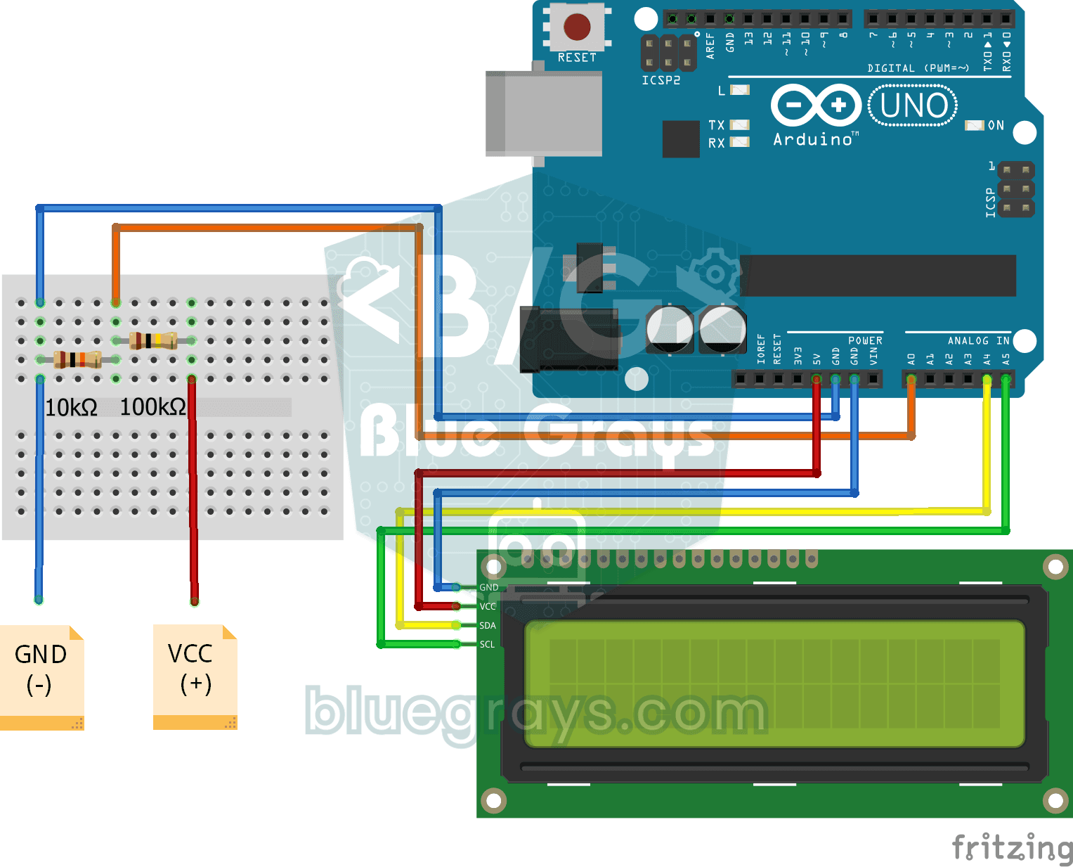
Digital Voltmeter with LCD Display
Find out how much voltage a battery or power adapter gives with a meter you built yourself. A divider made of two resistors brings high voltage down to a level the board can read, and the Arduino calc
Using a Servo Motor
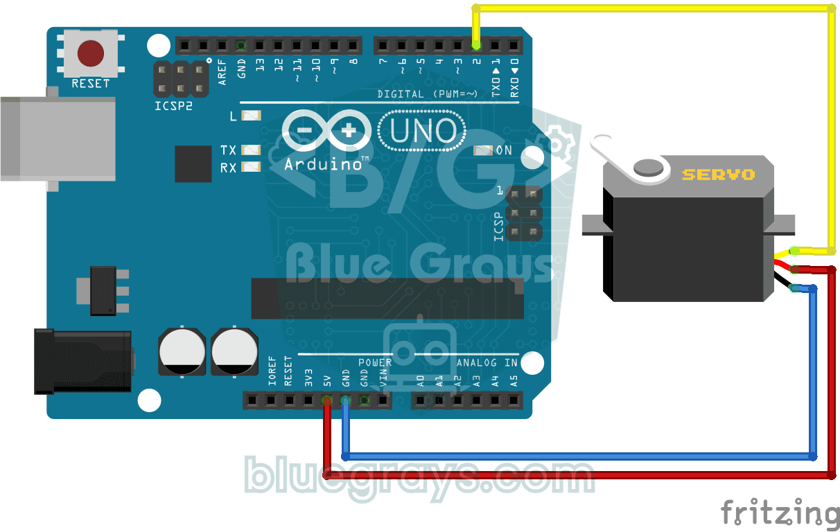
The arm of a small servo motor turns to three positions in turn: all the way to the start, right to the middle and all the way to the end, waiting two seconds at each stop. The Arduino tells the motor

Bluetooth Controlled Car with L298N
Turn your phone into a remote and drive your own robot car. The Arduino receives commands from a remote-control app on your phone through a Bluetooth module and spins the wheels with a motor driver; t

Obstacle Avoidance Robot
How about building a smart vehicle that finds its own way? The Obstacle Avoidance Robot constantly scans its surroundings thanks to the ultrasonic sensor in front of it. When it encounters an obstacle

Servo Circle Choreography - Animated Patterns with 32 Servos
A visual animation project using 32 servo motors arranged in a circle on an Arduino Mega. The servos are managed in a single array, connected to Mega's pins 22-53, and exhibit four different motion sequences: a chaotic vibration where all servos move at random angles, a synchronous sweep where they all move at the same time, a smoothly rotating wave around a circle, and finally a compass needle swinging left and right. The swirling wave effect is created by the rotation of each servo relative to

ESP32 WS2812B NeoPixel Strip Control
WS2812B (NeoPixel) addressable LEDs are smart RGB LEDs that can be controlled in a daisy-chain configuration via a single data pin. In this project, we will control an 8-LED WS2812B strip using the Adafruit_NeoPixel library to create a smooth rainbow animation. While the ESP32’s 3.3V logic level works seamlessly with most WS2812B components, we’ll demonstrate a solution using a 470Ω series resistor and a 1000µF capacitor in case of instability. The animation is achieved by shifting the hue value

Smart Irrigation Station
A gardener that waters your plants on its own, so they don't dry out while you're on vacation. A soil moisture sensor measures how wet the soil is; when it gets dry, the Arduino runs the water pump fo