
Arduino MOSFET Guide: Switch 12V LED Strips, Motors and Pumps
How to use a MOSFET with Arduino: logic-level IRLZ44N vs IRF520, gate and pull-down resistors, flyback diode, PWM code for 12V LED strips, motors and pumps.
An Arduino MOSFET circuit is the most efficient way to switch loads that draw several amps, such as a 12 V LED strip, a DC motor, a water pump or a solenoid lock, using Arduino pins that can only supply around 20 mA. A MOSFET is a voltage-controlled electronic switch: apply 5 V to its gate and the path between drain and source becomes almost a zero-resistance wire; at 0 V it's completely cut off. A well-chosen logic-level MOSFET only gets slightly warm while carrying a 3 A load without a heatsink.
In this guide you'll learn how a MOSFET works, why not every MOSFET suits an Arduino (the difference between the IRLZ44N and the IRF520), what the gate resistor, the pull-down resistor and the flyback diode do, and how to set speed and brightness with PWM. Further down you'll find ready-to-use code for a 12 V LED strip, a DC motor, a pump and a solenoid, ESP32 and Raspberry Pi Pico examples, heat and heatsink calculations, and a MOSFET vs transistor vs relay comparison table.
What is a MOSFET and how does it work?
A MOSFET (Metal Oxide Semiconductor Field Effect Transistor) is a field-effect transistor with three legs: the gate, the drain and the source. The gate is insulated from the rest of the device by a thin oxide layer, so no steady current flows into it and it behaves like a small capacitor. When the voltage between gate and source (VGS) rises above a certain threshold, a conductive channel forms between drain and source and the load current flows through it. A classic BJT transistor is driven by base current, whereas a MOSFET is driven by voltage; the Arduino pin only supplies current during the few microseconds it takes to charge and discharge the gate.
Arduino projects almost always use an N-channel MOSFET placed on the negative (GND) side of the load; this is called low-side switching. The load's positive lead goes straight to the positive terminal of the external supply, its negative lead goes to the MOSFET's drain, and the source connects to GND. That way the gate-to-source voltage is simply the voltage of the Arduino pin. These are the datasheet values you need to check:
| Parameter | Meaning | IRLZ44N value |
|---|---|---|
| VDS | Highest voltage the drain–source path can withstand; should be at least 1.5–2 times the supply voltage | 55 V |
| ID | Continuous drain current; only valid with the case held at 25 °C, in practice you use far less | 47 A (VGS = 10 V) |
| VGS(th) | Gate voltage at which the channel just starts to conduct (only 250 µA flows); not the fully-on voltage | 1.0–2.0 V |
| RDS(on) | Drain–source resistance when fully on; it sets the heating, and the VGS it was measured at matters a lot | 22 mΩ (10 V), 25 mΩ (5 V), 35 mΩ (4 V) |
| VGS (max) | Highest voltage you may apply to the gate; exceed it and the oxide layer breaks down | ±16 V |
| Qg | Charge needed to switch the gate fully on; the larger it is, the slower the switching | 48 nC |
| Body diode | Diode built into the structure from source to drain; it does not protect inductive loads | Yes (in every power MOSFET) |
Logic-level MOSFETs: IRLZ44N, IRF520 and others
The most common mistake is to look at VGS(th) and think "the threshold is 4 V, the Arduino gives 5 V, so it'll work". The threshold is the point where the channel lets through just 250 µA; for the MOSFET to carry several amps with low resistance, the gate voltage has to be well above the threshold. The right question is: at which VGS does the datasheet guarantee RDS(on)? If it's given for 4.5 V or 5 V, the MOSFET turns fully on from a 5 V Arduino, and it's called a logic-level MOSFET. If it's only given for 10 V, it's a standard MOSFET and an Arduino pin will only turn it half on. In International Rectifier's (now Infineon) naming, parts starting with IRL (IRLZ44N, IRLB8721, IRL540N) are logic level, whereas the IRFZ44N, IRF520 and IRF540N are standard.
| Model (package) | VDS | Continuous ID | RDS(on) (test condition) | VGS(th) | Arduino Uno (5 V) | ESP32 / Pico (3.3 V) |
|---|---|---|---|---|---|---|
| IRLZ44N (TO-220) | 55 V | 47 A | 25 mΩ (VGS = 5 V) | 1.0–2.0 V | Excellent; up to 3 A without a heatsink | Typically up to 2–3 A, not guaranteed |
| IRLB8721 (TO-220) | 30 V | 62 A | 16 mΩ (VGS = 4.5 V) | 1.35–2.35 V | Excellent | Typically up to 2–3 A, not guaranteed |
| AO3400A (SOT-23, SMD) | 30 V | 5.7 A | 48 mΩ (VGS = 2.5 V) | 0.65–1.45 V | Good; small loads (≈2 A) | Excellent; guaranteed even at 2.5 V |
| IRFZ44N (TO-220) | 55 V | 49 A | 17.5 mΩ (VGS = 10 V only) | 2.0–4.0 V | Unsuitable, only half on | Don't use |
| IRF520 and its module (TO-220) | 100 V | 9.2 A | 0.27 Ω (VGS = 10 V only) | 2.0–4.0 V | Only up to ≈1 A | Don't use |
| IRF540N (TO-220) | 100 V | 33 A | 44 mΩ (VGS = 10 V only) | 2.0–4.0 V | Unsuitable, only half on | Don't use |
The rule from the table is simple: for 5 V boards such as the Uno, Nano and Mega, choose a MOSFET whose RDS(on) is specified at 4.5 V or 5 V. On 3.3 V boards like the ESP32 and Pico it's a bit harder, because the datasheets of popular TO-220 MOSFETs such as the IRLZ44N and IRLB8721 don't guarantee any value at 3.3 V; we'll come back to this in the ESP32 section. Don't choose by the package either: the IRLZ44N and IRFZ44N come in the same package with almost the same marking, but that single letter (L) changes everything for an Arduino. You can check the pin order with the Transistor Pinout List tool; on TO-220 MOSFETs, with the printed side facing you, the order from left to right is gate, drain, source, and the metal tab is connected to the drain.
Arduino MOSFET wiring: gate resistor, pull-down and common ground
The basic circuit has five parts: the MOSFET, a gate resistor, a pull-down resistor, a flyback diode for inductive loads, and an external power supply. The table below shows the wiring for three boards; the example load is a 12 V LED strip or motor. All the code in this article uses these pins.
| Connection | Arduino Uno | ESP32 | Raspberry Pi Pico |
|---|---|---|---|
| Control pin → gate resistor → gate | D9 (PWM), 220 Ω | GPIO 25, 100 Ω | GP15, 100 Ω |
| Pull-down between gate and GND | 10 kΩ | 10 kΩ | 10 kΩ |
| Source | GND | GND | GND |
| Drain | Load negative (−) lead | Load negative (−) lead | Load negative (−) lead |
| Load positive (+) lead | 12 V adapter positive | 12 V adapter positive | 12 V adapter positive |
| 12 V adapter negative (−) | Arduino GND (common ground) | ESP32 GND (common ground) | Pico GND (common ground) |
| Recommended MOSFET | IRLZ44N | IRLZ44N (up to 2–3 A) or AO3400A | IRLZ44N (up to 2–3 A) or AO3400A |
The gate resistor (100–220 Ω) limits the momentary current drawn from the pin while the gate capacitance charges. The IRLZ44N's input capacitance is about 1700 pF; without a resistor the pin briefly sees something close to a short circuit on every transition, and the gate line starts ringing. With 220 Ω the peak current is at most 5 / 220 ≈ 23 mA, and the gate still charges within a few microseconds. The pull-down resistor (10 kΩ) keeps the gate from floating while the pin is an input, which happens while the Arduino starts up, resets or receives a new sketch. A floating gate can pick up noise and charge halfway; the MOSFET then sits half on, spins the motor by itself and quickly overheats. Put the pull-down on the MOSFET side of the gate resistor, directly between gate and source, so the MOSFET stays off even if the control wire comes loose. The two resistors form a small voltage divider, but the effect is negligible: 5 × 10000 / 10220 ≈ 4.89 V reaches the gate.
Flyback diode: why motors, pumps and solenoids need one
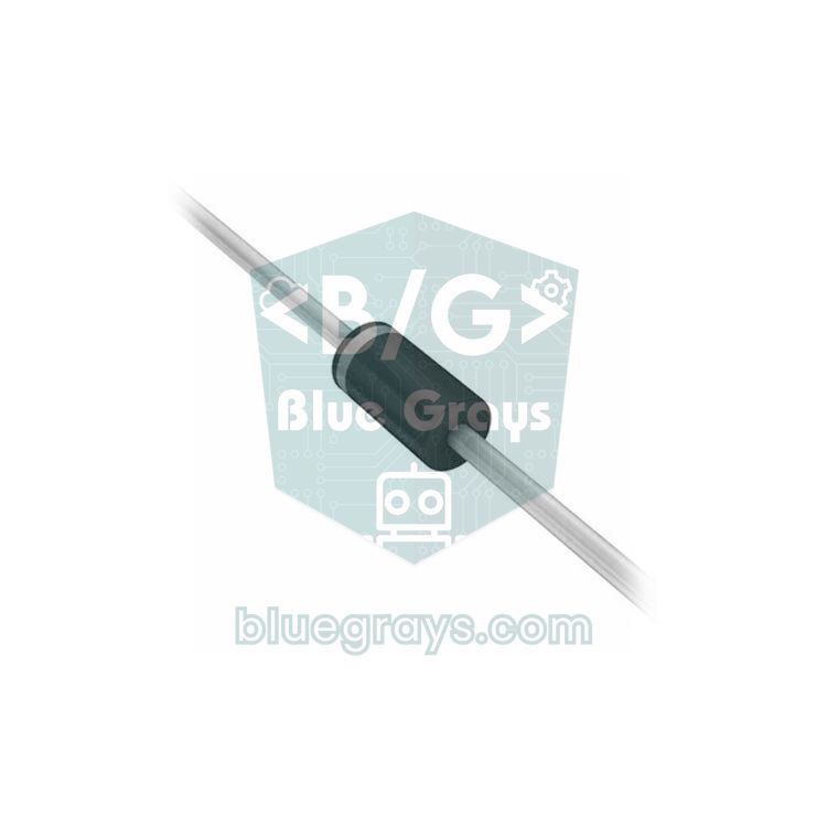
Inductive loads such as motors, pumps, solenoids, relay coils and fans resist a sudden stop in current. The moment the MOSFET switches off, the magnetic energy stored in the coil is released as a voltage spike on the drain that rises far above the supply voltage (V = L × di/dt). That spike can exceed the MOSFET's VDS rating and destroy it, or create interference that resets the Arduino. The fix is a diode connected in reverse across the load: the cathode (banded end) goes to the positive supply, the anode to the drain. In normal operation the diode is reverse-biased and carries no current; when the MOSFET turns off, the coil current circulates through the diode and dies away gently. The MOSFET's body diode can't do this job, because it sits between source and drain, not across the load. For more detail, see What Is a Diode?.
| Load and drive mode | Recommended diode | Why? |
|---|---|---|
| Solenoid, relay coil (on/off only) | 1N4007 (1 A, 1000 V) | A slow diode, but enough for occasional switching |
| Small pump or motor with PWM (up to 1 A) | 1N5819 Schottky (1 A, 40 V) | Fast; it conducts in every PWM period |
| Larger motor with PWM (1–3 A) | 1N5822 or SS34 Schottky (3 A, 40 V) | While the PWM is off, the diode carries the full motor current |
| 12 V LED strip, resistive heater | Not needed | No coil, so no voltage spike |
Step by step: dimming a 12 V LED strip with Arduino
- Gather the parts: Arduino Uno, IRLZ44N, 220 Ω and 10 kΩ resistors, a 10 kΩ potentiometer, a 12 V LED strip and a 12 V adapter that can supply the strip's current.
- Work out the strip's current: a 5050 strip with 60 LEDs/m draws about 14.4 W per metre, which is 1.2 A at 12 V. Two metres need 2.4 A; choose the adapter with a 20% margin (at least 3 A).
- Place the MOSFET: connect the IRLZ44N's source to the GND rail, its gate to D9 through 220 Ω, and put 10 kΩ between gate and GND.
- Connect the load: the strip's +12V wire goes to the adapter's positive, its negative wire to the MOSFET's drain. Breadboard contacts handle about 1 A; for more current, use screw terminals or solder the load wires.
- Connect the potentiometer: outer legs to 5V and GND, middle leg to A0.
- Join the grounds and test: connect the adapter's negative to the Arduino's GND, upload the code, then plug in the adapter.
1// IRLZ44N ile 12 V LED şerit parlaklık kontrolü / 12 V LED strip dimming with an IRLZ44N
2const int STRIP_PIN = 9;    // PWM pini, 220 Ω ile gate'e / PWM pin, to the gate via 220 Ω
3const int POT_PIN = A0;     // potansiyometre orta ucu / potentiometer wiper
4
5void setup() {
6  pinMode(STRIP_PIN, OUTPUT);
7  digitalWrite(STRIP_PIN, LOW);             // açılışta kapalı / off at startup
8  Serial.begin(9600);
9}
10
11void loop() {
12  int pot = analogRead(POT_PIN);            // 0–1023
13  float x = pot / 1023.0;                   // 0.0–1.0
14  int duty = (int)(x * x * 255.0 + 0.5);    // basit gama düzeltmesi / simple gamma correction
15  analogWrite(STRIP_PIN, duty);             // D9'da 490 Hz PWM / 490 Hz PWM on D9
16  Serial.print("Parlaklik / Brightness: %");
17  Serial.println(duty * 100 / 255);
18  delay(50);
19}
analogWrite() produces a PWM signal on pin 9 that switches on and off about 490 times per second; 0 means fully off and 255 fully on. The Uno's PWM pins are 3, 5, 6, 9, 10 and 11; pins 5 and 6 run at about 980 Hz. Because the eye doesn't perceive brightness linearly, squaring the potentiometer value (a simple gamma correction) gives much smoother control at low brightness. You'll find the details of PWM in What Is PWM?. Let's also check the heat: at 2.4 A the IRLZ44N dissipates P = I² × RDS(on) = 2.4² × 0.025 ≈ 0.14 W, so it only feels lukewarm to the touch. Meanwhile the LED strip itself uses 28.8 W; the loss in the MOSFET is less than one percent of the total.
DC motor and pump speed control with PWM
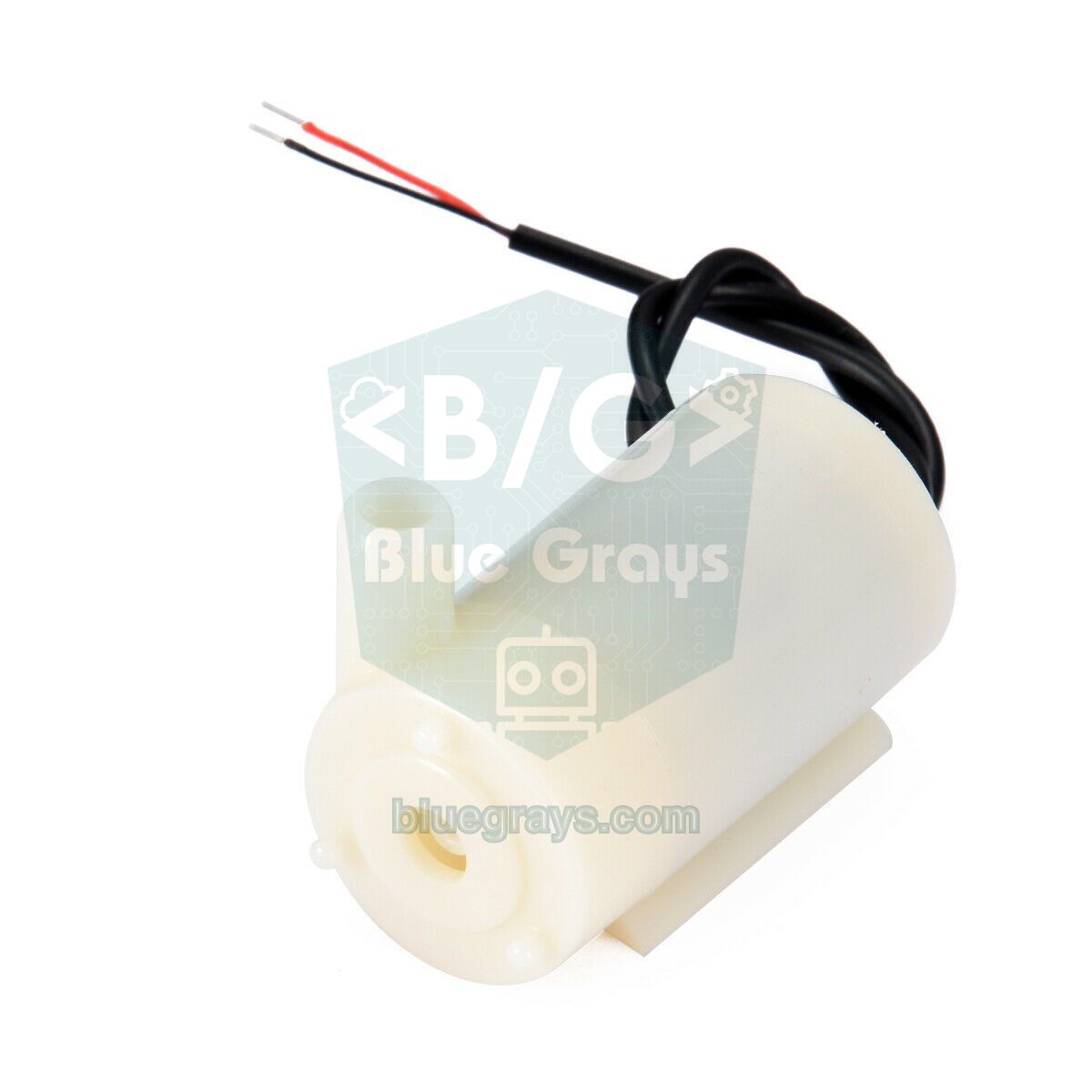
Driving a motor or pump uses the same circuit as the LED strip; the only difference is that you add a flyback diode across the load. Motors also have an inrush current: a stationary motor can draw 3–8 times its running current at the first instant. So size the MOSFET and power supply for the motor's stall current, and use a soft start instead of jumping straight from 0 to 255. Mini submersible pumps draw about 0.1–0.3 A at 3–6 V, while 12 V diaphragm pumps usually draw 0.5–1 A; the IRLZ44N handles both with plenty of margin. Just power a mini pump from a supply at its own voltage (5–6 V), not from the 12 V adapter; the MOSFET circuit stays the same. For pump selection and watering details, see Mini Water Pump.
1// IRLZ44N ile motor/pompa hız kontrolü ve yumuşak kalkış / Motor or pump speed control with soft start (IRLZ44N)
2const int MOTOR_PIN = 9;     // 220 Ω ile gate'e / to the gate via 220 Ω
3const int POT_PIN = A0;      // hız ayarı / speed setting
4const int MIN_DUTY = 60;     // bunun altında motor yalnızca vızıldar / below this the motor only hums
5
6int current = 0;             // şu anki PWM değeri / current PWM value
7
8void setup() {
9  pinMode(MOTOR_PIN, OUTPUT);
10  digitalWrite(MOTOR_PIN, LOW);
11  // TCCR1B = (TCCR1B & 0b11111000) | 0x02;   // isteğe bağlı: D9/D10 PWM ≈3,9 kHz / optional: D9/D10 PWM ≈3.9 kHz
12}
13
14void loop() {
15  int target = map(analogRead(POT_PIN), 0, 1023, 0, 255);
16  if (target < MIN_DUTY) target = 0;         // çok düşük hızda tamamen durdur / stop completely at very low speed
17
18  if (current < target) current++;           // yavaşça hızlan / speed up gently
19  else if (current > target) current--;      // yavaşça yavaşla / slow down gently
20
21  analogWrite(MOTOR_PIN, current);
22  delay(8);                                  // 0→255 yaklaşık 2 s / 0→255 takes about 2 s
23}
The code moves one step towards the target speed read from the potentiometer every 8 ms, so the motor goes from 0 to full speed in about 2 seconds and the inrush current doesn't drag down the power supply. MIN_DUTY is the lowest PWM value at which the motor starts to turn; find it by experimenting with your own motor. The 490 Hz PWM makes an audible whine in the motor. The commented-out TCCR1B line raises the frequency of D9 and D10 to about 3.9 kHz; the Servo library also uses Timer1, so don't use the two together. Pushing the frequency even higher is tempting, but because an Arduino pin needs a few microseconds to charge a large MOSFET's gate on every transition, switching losses grow with frequency: at around 20 kHz even a 2 A motor can cause more than 1 W of loss in the MOSFET. At those frequencies a gate driver such as the TC4427 is used.
Solenoid locks and short-duty loads
12 V solenoid door locks draw 0.5–1 A, and most aren't designed to be energised continuously; left on for long, the coil heats up. So the code should keep the lock open for just a few seconds. Since the solenoid is switched on and off rather than driven with PWM, a 1N4007 is enough as the flyback diode. In the example below, pressing the button on D2 opens the lock for 3 seconds, after which it closes even if the button is still held. To trigger the lock with an RFID card reader or a keypad, you only need to change the if condition; for lock types and behaviour during a power cut, see Solenoid Lock.
1// Butonla 3 saniyelik solenoid kilit açma / Open a solenoid lock for 3 seconds with a button
2const int LOCK_PIN = 9;                 // 220 Ω ile IRLZ44N gate'ine / to the IRLZ44N gate via 220 Ω
3const int BUTTON_PIN = 2;               // buton D2 ile GND arasında / button between D2 and GND
4const unsigned long OPEN_MS = 3000;     // kilidin açık kalma süresi / how long the lock stays open
5
6void setup() {
7  pinMode(LOCK_PIN, OUTPUT);
8  digitalWrite(LOCK_PIN, LOW);          // kilit kapalı / locked
9  pinMode(BUTTON_PIN, INPUT_PULLUP);    // basılınca LOW / LOW when pressed
10}
11
12void loop() {
13  if (digitalRead(BUTTON_PIN) == LOW) {
14    digitalWrite(LOCK_PIN, HIGH);       // solenoid çeker, kilit açılır / solenoid pulls in, lock opens
15    delay(OPEN_MS);
16    digitalWrite(LOCK_PIN, LOW);        // bobini soğumaya bırak / let the coil cool down
17    while (digitalRead(BUTTON_PIN) == LOW) {}   // buton bırakılana kadar bekle / wait until released
18    delay(50);                          // buton zıplamasını süz / debounce
19  }
20}
Why the IRF520 module falls short at 5 V
The IRF520 MOSFET module, very common in starter kits, is a small board with screw terminals sold with ratings like "24 V, 5 A". Next to the MOSFET it carries a few resistors and a signal LED; most versions have no flyback diode. The problem is the MOSFET itself: the IRF520 is a standard MOSFET with a threshold of 2–4 V, and its 0.27 Ω RDS(on) is only guaranteed at VGS = 10 V. According to the typical curves in the datasheet, at a 5 V gate voltage the IRF520 starts limiting the current at around 2 A; with a high-threshold part, that limit drops below 1 A. At that point the MOSFET behaves not like a switch but like a variable resistor.
Here's an example: imagine driving a 12 V motor that draws 2 A with the IRF520 module. If 1.5 V drops across the MOSFET, it dissipates P = 1.5 × 2 = 3 W. With a TO-220 package's thermal resistance of 62 °C/W without a heatsink, that's about 186 °C above ambient; the MOSFET quickly overheats and fails, or at best the motor turns slowly. The 5 A on the module's label only applies with 10 V on the gate. These are the module's terminals and how to connect them:
| Module terminal | Connect to | Note |
|---|---|---|
| SIG | Arduino PWM pin (e.g. D9) | Gate signal; barely turns on at all with 3.3 V boards |
| VCC | Arduino 5V | Not connected to anything on most versions; no load current flows here |
| GND (pin header) | Arduino GND | Required for the common ground |
| VIN and GND (screw terminal) | External supply + and − | Power for the load; the module is sold for up to 24 V |
| V+ and V− (screw terminal) | Load + and − | For motors and pumps, add a diode between V+ and V− (cathode to V+) |
- Swap the MOSFET: desolder the IRF520 from the module and solder in an IRLZ44N with the same pin order (G-D-S); the board works exactly the same, but now turns fully on at 5 V.
- Use a logic-level module: ready-made modules with the AOD4184A (D4184) MOSFET offer an RDS(on) of at most 9.5 mΩ at 4.5 V and work comfortably with a 5 V Arduino.
- Drive the gate with a higher voltage: a gate driver such as the TC4427, powered from 12 V, turns the Arduino's 5 V or 3.3 V signal into 12 V at the gate, so the IRF520 reaches its real capability. Keep the gate voltage within limits: ±20 V for the IRF520, ±16 V for the IRLZ44N.
- Use it as is for small loads: below 1 A (a short LED strip, a mini pump) the IRF520 module works at 5 V with acceptable heating; if the MOSFET gets too hot to touch, reduce the load.
Using a MOSFET with ESP32 and Raspberry Pi Pico (3.3 V)
Because the ESP32 and Pico pins output 3.3 V, choosing the right MOSFET matters even more. The IRLZ44N datasheet specifies RDS(on) down to 4 V; according to the typical curves it still passes several amps comfortably at around 3 V, but that isn't guaranteed for a part with a high threshold. A practical rule: on 3.3 V boards, use the IRLZ44N or IRLB8721 for up to 2–3 A, measure the drain-to-source voltage with a multimeter while the load is running, and work out the dissipated power with P = VDS × I; stay below 1 W for a TO-220 without a heatsink. For larger currents use a driver that raises the gate to 5–12 V, and for small loads an AO3400A, whose RDS(on) is guaranteed at 2.5 V. On the ESP32, pick pins such as GPIO 25, 26, 27, 32 or 33 for the MOSFET: GPIO 0, 2, 5, 12 and 15 are strapping pins, and GPIO 1, 3, 5, 14 and 15 may go HIGH briefly or output PWM at boot. On those pins the load can switch on unexpectedly at startup, or the pull-down resistor can interfere with booting.
The ESP32 code below starts a pump through the MOSFET with a soft start when the soil moisture sensor reports dry soil, waters for 5 seconds and then stops it gently. For PWM it uses the ledcAttach() and ledcWrite() functions from ESP32 Arduino core 3.x; the older 2.x versions used ledcSetup() and ledcAttachPin() instead, and their ledcWrite() took a channel number rather than a pin. The #if lines in the code pick the right calls for the installed core, so it compiles on both versions. Because the gate is driven at 3.3 V through 100 Ω, the frequency is kept at 1 kHz so switching losses stay negligible. Measure the sensor's dry and wet readings in your own soil, as in Soil Moisture Sensor, and set the DRY_LEVEL threshold accordingly.
1// ESP32 + MOSFET ile otomatik sulama pompası / Automatic watering pump with ESP32 + MOSFET
2const int PUMP_PIN = 25;                 // 100 Ω ile gate'e, gate–GND 10 kΩ / to the gate via 100 Ω, 10 kΩ gate–GND
3const int SOIL_PIN = 34;                 // toprak nem sensörü, ADC1 / soil moisture sensor, ADC1
4const int DRY_LEVEL = 2800;              // üstü kuru sayılır, kalibre et / above this counts as dry, calibrate
5const unsigned long WATER_MS = 5000;     // sulama süresi / watering time
6
7void pumpWrite(int duty) {               // 0–255 PWM, iki çekirdek sürümünde / on both core versions
8#if ESP_ARDUINO_VERSION_MAJOR >= 3
9  ledcWrite(PUMP_PIN, duty);             // 3.x: pin numarasıyla / 3.x: by pin number
10#else
11  ledcWrite(0, duty);                    // 2.x: kanal 0 ile / 2.x: by channel 0
12#endif
13}
14
15void pumpRamp(int from, int to) {        // yumuşak hız değişimi / smooth speed change
16  int step = (to > from) ? 5 : -5;
17  for (int d = from; d != to; d += step) {
18    pumpWrite(d);
19    delay(20);
20  }
21  pumpWrite(to);
22}
23
24void setup() {
25  Serial.begin(115200);
26#if ESP_ARDUINO_VERSION_MAJOR >= 3
27  ledcAttach(PUMP_PIN, 1000, 8);         // 1 kHz, 8 bit (0–255); çekirdek 3.x / core 3.x
28#else
29  ledcSetup(0, 1000, 8);                 // çekirdek 2.x: kanal 0 / core 2.x: channel 0
30  ledcAttachPin(PUMP_PIN, 0);
31#endif
32  pumpWrite(0);                          // pompa kapalı / pump off
33}
34
35void loop() {
36  int soil = analogRead(SOIL_PIN);       // 0–4095
37  Serial.printf("Toprak / Soil: %d\n", soil);
38  if (soil > DRY_LEVEL) {
39    pumpRamp(0, 255);                    // yaklaşık 1 s'de tam hıza / full speed in about 1 s
40    delay(WATER_MS);
41    pumpRamp(255, 0);                    // yumuşakça dur / stop gently
42    delay(60000);                        // suyun toprağa yayılmasını bekle / let the water soak in
43  }
44  delay(1000);
45}
On the Raspberry Pi Pico, the machine.PWM class is all you need to generate PWM in MicroPython; duty_u16() takes a value from 0 to 65535. The code below gives a 12 V LED strip on the MOSFET at GP15 a smooth "breathing" effect. As in the Arduino example, the value is squared for a simple gamma correction, so the transition from dark to bright looks natural. The Pico's pins also output 3.3 V, so the MOSFET rules we gave for the ESP32 apply here too.
1# Pico + MOSFET ile 12 V LED şerit nefes efekti / 12 V LED strip breathing effect with Pico + MOSFET
2from machine import Pin, PWM
3import time
4
5strip = PWM(Pin(15))          # 100 Ω ile gate'e, gate–GND 10 kΩ / to the gate via 100 Ω, 10 kΩ gate–GND
6strip.freq(1000)              # 1 kHz: titreme görünmez / 1 kHz: no visible flicker
7
8def set_level(x):             # x: 0.0–1.0
9    strip.duty_u16(int(x * x * 65535))   # basit gama düzeltmesi / simple gamma correction
10
11while True:
12    for i in range(101):                 # yavaşça aydınlan / fade in
13        set_level(i / 100)
14        time.sleep_ms(20)
15    for i in range(100, -1, -1):         # yavaşça sön / fade out
16        set_level(i / 100)
17        time.sleep_ms(20)
18    time.sleep_ms(500)
Heat, power calculation and choosing a heatsink
The heat in a fully-on MOSFET comes from a single formula: P = I² × RDS(on). Keep two things in mind. First, RDS(on) rises with temperature; for the IRLZ44N at 100 °C it's about 1.5 times the 25 °C value, so using 38 mΩ instead of 25 mΩ in the calculation is more realistic. Second, the package can only shed so much heat into the air: the thermal resistance of a TO-220 without a heatsink (RθJA) is 62 °C/W, meaning every watt raises the die temperature 62 °C above ambient. The table below shows how the IRLZ44N heats up with a 5 V gate and no heatsink:
| Load current | Power dissipated (at 38 mΩ) | Temperature rise (no heatsink) | Recommendation |
|---|---|---|---|
| 1 A | 0.04 W | ≈ 2 °C | No heatsink needed |
| 3 A | 0.34 W | ≈ 21 °C | No heatsink needed, warm |
| 5 A | 0.95 W | ≈ 59 °C | Borderline; fit a small heatsink |
| 8 A | 2.4 W | ≈ 150 °C | Heatsink required |
| 10 A | 3.8 W | ≈ 236 °C | Finned heatsink and thermal paste required |
Heatsink sizing follows the same logic: Tj = Tambient + P × (RθJC + RθCS + RθSA). If 3.8 W is dissipated at 10 A and you want to keep the die at 100 °C in a 30 °C room, the total thermal resistance must not exceed (100 − 30) / 3.8 ≈ 18 °C/W. The IRLZ44N's junction-to-case resistance is 1.4 °C/W and a contact with thermal paste is about 0.5 °C/W, so the heatsink itself must be 16 °C/W or less, which matches a small but finned TO-220 heatsink. The MOSFET's metal tab is connected to the drain; if you mount several MOSFETs on the same heatsink, use a mica or silicone insulating pad and a plastic screw bushing. The second source of heat with PWM is switching loss; it's negligible at 490 Hz but grows as the frequency rises.
MOSFET vs transistor vs relay
| Feature | Logic-level MOSFET (IRLZ44N) | BJT transistor (2N2222A / TIP120) | Relay (5 V module) |
|---|---|---|---|
| How is it controlled? | By voltage; no steady gate current | By current; base current flows constantly (2–10 mA) | By coil current (≈70 mA); the module's transistor drives it |
| Loss when on | I² × RDS(on): ≈ 0.2–0.3 W at 3 A | VCE(sat) × I: TIP120 up to 2 V at 3 A, ≈ 6 W | Almost zero across the contacts |
| Current capacity | Tens of amps (with a heatsink) | 2N2222A 0.6 A, TIP120 5 A | Usually 10 A (contact rating) |
| PWM speed and brightness | Yes, in the kHz range | Yes | No, on/off only |
| AC / mains voltage | No, DC only | No, DC only | Yes, with galvanic isolation |
| Noise and lifetime | Silent, no wear | Silent, no wear | Clicks; contact life about 100,000 operations |
| Best for | LED strips, motors, pumps, solenoids (1–10 A DC) | Small loads (up to 1 A), relay coils, buzzers | Lamps, sockets, AC appliances |
In short: if you want to control a DC load quickly, silently and with PWM, use a MOSFET; if you're switching a mains-powered lamp or socket, use a relay module. For small loads of a few hundred milliamps, a cheap BJT also does the job; you'll find the base resistor calculation in What Is a Transistor?. If the same motor has to turn in both directions, one MOSFET isn't enough: you need an H-bridge with four switches, so use an L298N motor driver or a MOSFET H-bridge module.
MOSFET project ideas
- Automatic cupboard or stair light: when a PIR sensor detects motion, fade a 12 V LED strip on with PWM and switch it off after a while.
- Sunset lamp: use an LDR to raise the strip's brightness step by step as the room gets darker.
- Smart fan: speed up a 12 V PC fan as the temperature measured by a DHT11 rises.
- Automatic plant watering: water your pots on their own with a soil moisture sensor and a pump driven by a MOSFET; use a separate MOSFET for each pump.
- Card-operated door lock: open a 12 V solenoid lock for 3 seconds when an RFID RC522 reads the right card.
- Smart greenhouse: build a smart greenhouse that controls the fan, pump and heater with separate MOSFETs.
Common mistakes and how to fix them
| Symptom | Likely cause | Fix |
|---|---|---|
| The load doesn't run at all | No common GND, or wrong G-D-S order | Connect the adapter's negative to the Arduino's GND and check the pin order |
| The load runs all the time and won't switch off | Drain and source swapped (body diode conducting), or the MOSFET has failed short | Correct the wiring; if drain–source measures as a short in both directions, replace the MOSFET |
| The MOSFET gets very hot and the load is weak | A standard MOSFET (IRF520, IRFZ44N) only half on at 5 V or 3.3 V | Use a logic-level MOSFET such as the IRLZ44N, or a gate driver |
| The motor spins by itself at power-up or during upload | Floating gate, no pull-down resistor | Put 10 kΩ between gate and GND |
| The Arduino resets when the motor stops | No flyback diode, or motor and Arduino share a weak supply | Add a Schottky diode in reverse across the motor and power the motor from a separate supply |
| The motor whines loudly with PWM | The 490 Hz PWM frequency is in the audible range | Raise it to 3.9 kHz; above 20 kHz, use a gate driver |
| The load is weak with the N-channel MOSFET on the positive side | The source rises with the load, so VGS shrinks | Keep the N-channel on the GND side; for high-side switching use a P-channel MOSFET with an NPN driver |
A MOSFET is the cleanest way to connect an Arduino to powerful real-world loads: with a well-chosen logic-level part, a gate resistor, a pull-down and a diode for inductive loads, you can control any DC load from an LED strip to a pump silently and efficiently. In the BlueGrays app you'll find projects such as PWM LED fading, potentiometer brightness control, a smart watering station and smart lighting, with step-by-step circuit diagrams and code, so you can turn the MOSFET circuit you learned here into a real project right away.
Frequently asked questions
Which MOSFET should I use with Arduino?
For a 5 V Arduino Uno, Nano or Mega, choose a logic-level N-channel MOSFET whose RDS(on) is guaranteed at 4.5 V or 5 V. The most common is the IRLZ44N: it handles 55 V and has only 25 mΩ of resistance with a 5 V gate. The IRLB8721 is also a good choice, whereas standard MOSFETs like the IRFZ44N, IRF520 and IRF540N need 10 V to turn fully on.
Does the IRF520 module work with Arduino?
It works, but with limits. The IRF520 is a standard MOSFET and with a 5 V gate it typically starts limiting the current at around 2 A, so it heats up quickly with loads above 1 A. It's fine for small loads; for more, replace the module's MOSFET with an IRLZ44N or use a logic-level module.
What value gate resistor should I use for a MOSFET?
With an Arduino, a gate resistor of 100–220 Ω works well; 220 Ω limits the momentary current from the pin to about 23 mA at 5 V. Also put a 10 kΩ pull-down resistor between gate and GND, which stops the MOSFET from switching on by itself at power-up and during uploads.
Can a MOSFET switch mains AC voltage?
In Arduino projects, use a MOSFET for DC loads only. Mains AC can't be switched safely with a single N-channel MOSFET, and such a circuit has no isolation, which makes it dangerous. For a mains lamp or socket, use a relay module, a solid-state relay (SSR) or an optocoupler-driven triac circuit.
How do I drive a MOSFET with an ESP32?
Because the ESP32's pins output 3.3 V, choose a MOSFET that turns on well at a low gate voltage. The IRLZ44N typically works well at 3.3 V up to 2–3 A; for small loads the AO3400A, guaranteed at 2.5 V, and for high currents a driver that raises the gate to 12 V are safer. Use ledcAttach() and ledcWrite() for PWM, and pick pins that stay quiet at boot, such as GPIO 25, 26, 27, 32 or 33.
Why does my MOSFET get hot?
The heat in a fully-on MOSFET is P = I² × RDS(on); an IRLZ44N dissipates only 0.2–0.3 W at 3 A. If the MOSFET runs very hot, the gate voltage is usually too low and it's only half on; using a standard MOSFET, driving it from a 3.3 V board and a very high PWM frequency are the most common causes. If a TO-220 without a heatsink has to dissipate more than 1 W, add a heatsink.
Projects to build after reading this
See all projects
Night Light with Ldr
A little night light that turns on by itself when it gets dark and goes off when morning comes. A light sensor measures how bright the room is, and the Arduino switches the LED on when it is dark enou

ESP32 LED Fade with PWM
Smoothly changing the brightness of the LED from 0 to max, from max to 0. We control PWM with analogWrite() as in Arduino - the same syntax as ESP32 Arduino Core 3.0+ works without problems. Pin definition + pinMode + analogWrite is enough.

ESP32 LED Brightness Control with a Potentiometer (Analog → PWM)
In this project, we control the brightness of an LED analogically using a potentiometer. The ESP32's ADC pin reads the 0-3.3V voltage from the potentiometer, and this value is then converted into a PWM (Pulse Width Modulation) signal and sent to the LED. As a result, as you turn the potentiometer, the LED gradually brightens and dims. With Arduino Core 3.0+, analogWrite() can be used directly; on the ESP32-S2/S3, the ADC resolution is fixed at 12-bit.
Raspberry Pi Pico PWM LED Fade (Breathing Effect)
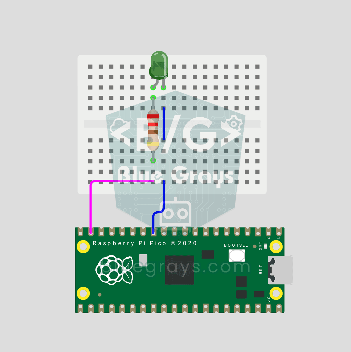
The LED no longer just blinks — it breathes! Using the Raspberry Pi Pico's PWM (Pulse Width Modulation), the LED brightness slowly rises and then slowly falls, like a sleeping MacBook's light. Learn the machine.PWM class, duty_u16() (16-bit brightness 0–65535), PWM frequency (freq(1000) — 1000 on/off cycles per second, no visible flicker), range() step loops (up and down) and analog-like output from a digital pin. PWM is a core embedded tool — RGB color mixing, motor

Smart Irrigation Station
A gardener that waters your plants on its own, so they don't dry out while you're on vacation. A soil moisture sensor measures how wet the soil is; when it gets dry, the Arduino runs the water pump fo

ESP32 Smart Lighting (PIR + LDR + Relay + OLED)
Turn your hallway, bathroom, or pantry into smart lighting with ESP32! Using a PIR motion sensor, LDR light sensor, and a relay module, we build the classic "light turns on when motion is detected in the dark" scenario — if the environment is already bright, motion does NOT trigger the light, saving energy during the day. The light stays on for 30 seconds; if motion continues, the timer resets and the light stays on longer. The SSD1306 OLED shows large-font status (ON / DAYTIME / WAITING), a cou

Smart Stair and Corridor Lighting
Step onto the stairs or into the hallway and the lights come on one step at a time in the direction you are walking. There is a distance sensor at each end; whichever one you pass, the eight LEDs ligh