
What Is an Optocoupler? PC817 and 4N35 Isolation with Arduino
What is an optocoupler and how does it work? PC817 and 4N35 pinout, CTR and resistor math, reading 12/24 V signals, mains sensing (H11AA1), relays and MOC3021.
An optocoupler (also called an optoisolator or photocoupler) is a small chip that carries a signal between two circuits using only light, with no electrical connection between them. Inside there's an infrared LED and a phototransistor facing it: when the circuit on one side lights the LED, the transistor on the other side turns on. Because there isn't a single wire between the two sides, voltage spikes and noise can't reach your microcontroller when you connect a 24 V industrial sensor, a car's 12 V line or a motor driver to your Arduino.
In this post you'll learn step by step what's inside an optocoupler, why galvanic isolation matters, the pins and ratings of the two most common models, the PC817 and the 4N35, the idea of CTR and how to calculate the resistors. Then you'll see how to isolate an Arduino output, read 12/24 V signals safely, use it with the ESP32 and Raspberry Pi Pico, the safety rules for mains sensing (H11AA1), the optocoupler in relay modules and driving a triac with the MOC3021.
What is an optocoupler and how does it work?
Inside the optocoupler's package there are two chips facing each other. On the input side is an infrared LED that runs on current just like a normal LED. On the output side is a phototransistor whose base is sensitive to light; instead of feeding current into the base, you shine light on it. Between the two chips sits a layer of plastic that is transparent but electrically insulating. This layer is designed to withstand thousands of volts.
- The circuit on the input side passes a few milliamps through the LED via a resistor.
- The LED emits infrared light; this light crosses the insulating layer and falls on the phototransistor.
- The light acts like the phototransistor's base current and lets current flow between collector and emitter; the transistor closes like a switch.
- When the LED goes off the light stops, the transistor goes back to blocking and the output circuit opens. The signal has crossed over without wires, using only light.
Depending on what sits on the output side, there are different types of optocouplers. Hobby projects mostly use phototransistor models, but sensing AC signals, firing a triac or isolating a fast data line need special types:
| Type | Example models | Output | Typical use |
|---|---|---|---|
| Phototransistor | PC817, EL817, 4N35, 4N25 | NPN phototransistor | Digital signal isolation, reading 12/24 V inputs, relay modules |
| Darlington output | 4N33, H11B1 | Darlington transistor | High output current from very low LED current (but slower) |
| AC input | H11AA1, PC814 | Two antiparallel LEDs + phototransistor | Mains sensing, zero-cross detection |
| Triac output | MOC3021, MOC3041, MOC3063 | Phototriac | Triac triggering, AC load control, SSRs |
| High-speed logic | 6N137, 6N138 | Photodiode + logic gate or transistor | MIDI, UART and fast digital line isolation |
Why is galvanic isolation needed?
Galvanic isolation means there is no direct conductive path between two circuits: no shared GND, no shared wire, and energy and information are carried some other way (light, a magnetic field). Arduino pins tolerate at most 5 V (3.3 V on the ESP32 and Pico). The 24 V of an industrial sensor, the short spikes of hundreds of volts a motor produces when switching, or noise induced in long cables can reach the microcontroller directly through a shared GND. An optocoupler physically cuts that path.
- Protection: even if something fails on the high-voltage side, the damage stays in the optocoupler; the Arduino, your computer's USB port and you stay safe.
- Noise and ground loops: motors, relays and long cables create noise on the GND line. When the grounds are separate, that noise doesn't get into the signal line; we cover common ground in detail in the GND and common ground post.
- Different voltage levels: because the output transistor is powered from outside, a 24 V signal easily becomes 3.3 V and a 5 V signal becomes 12 V. An optocoupler is also a slow but sturdy level shifter.
- Safety standards: in mains-connected devices the user side must be isolated from the mains; parts like the PC817 pass a 5000 V rms isolation test.
PC817 and 4N35 pinout and ratings
| Pin | PC817 (DIP-4) | 4N35 (DIP-6) |
|---|---|---|
| 1 | Anode (LED +) | Anode (LED +) |
| 2 | Cathode (LED −) | Cathode (LED −) |
| 3 | Emitter | Not connected |
| 4 | Collector | Emitter |
| 5 | None | Collector |
| 6 | None | Base (usually left open) |
| Parameter | PC817 | 4N35 |
|---|---|---|
| LED forward voltage (VF) | Typ. 1.2 V, max 1.4 V (at 20 mA) | About 1.2–1.3 V |
| LED maximum current | 50 mA | 60 mA |
| LED reverse voltage | Max 6 V | Max 6 V |
| CTR | 50–600% (at 5 mA, 5 V; depends on rank) | At least 100% (at 10 mA, 10 V) |
| Collector-emitter voltage (VCEO) | 35 V | 70 V |
| Collector current | Max 50 mA | Max 50 mA |
| Switching time | Typ. 3–4 µs (with a low load resistor) | About 10 µs |
| Isolation voltage | 5000 V rms | 5000 V rms |
On the PC817, pin 1 is marked with a dot; the letter A, B, C or D after "PC817" on the package shows the CTR rank. Parts such as the EL817, LTV817 and KP1010 are pin-compatible equivalents of the PC817. The 4N35 has six legs, so its base pin is brought out; you usually leave it open, and in very noisy environments a high-value resistor (e.g. 1 MΩ) between base and emitter can speed up turn-off.
What is CTR and how do you calculate the resistors?
CTR (Current Transfer Ratio) is the ratio of the collector current the output transistor can pass to the LED current: CTR = IC / IF × 100%. For example, with an optocoupler whose CTR is 100%, if you pass 5 mA through the LED you can draw at most about 5 mA from the output. CTR changes with temperature, drops over the years as the LED ages, and varies a lot even between parts of the same model. That's why you always design around the lowest value in the datasheet.
| PC817 rank | CTR range (IF = 5 mA) | Output current at 5 mA LED current |
|---|---|---|
| PC817A | 80–160% | 4–8 mA |
| PC817B | 130–260% | 6.5–13 mA |
| PC817C | 200–400% | 10–20 mA |
| PC817D | 300–600% | 15–30 mA |
| No letter | 50–600% | 2.5–30 mA (assume the worst) |
LED resistor: the input side is calculated exactly like an LED: R = (Vsupply − VF) / IF. To pass 10 mA from an Arduino Uno's 5 V pin you get (5 − 1.2) / 0.010 = 380 Ω; a standard 330 Ω gives about 11.5 mA and 390 Ω about 9.7 mA. On the ESP32, (3.3 − 1.2) / 0.010 = 210 Ω, so you use 220 Ω. The Raspberry Pi Pico's pins are set to 4 mA drive strength by default; here about 4.5 mA with 470 Ω is enough. If you don't want to do the math by hand, use the LED Resistor tool.
Output (pull-up) resistor: for the transistor to switch fully on (saturate), the current drawn by the pull-up must be smaller than what the CTR allows. A 10 kΩ pull-up to 5 V needs only 0.5 mA. With an unlettered PC817 the worst-case CTR is 50%, so 1 mA through the LED would be enough for 0.5 mA; giving it 5–10 mA leaves at least a fivefold margin. The Arduino's internal pull-up (about 20–50 kΩ) is ideal for this job too. A smaller pull-up makes the signal faster but needs more current; a larger one needs less current but makes the transistor turn off more slowly.
| Case | Supply voltage | Target LED current | Suggested resistor | Resistor power |
|---|---|---|---|---|
| Driving from an Arduino Uno pin | 5 V | ~10 mA | 330 Ω | 1/4 W is enough |
| Driving from an ESP32 pin | 3.3 V | ~10 mA | 220 Ω | 1/4 W is enough |
| Driving from a Raspberry Pi Pico pin | 3.3 V | ~4.5 mA | 470 Ω | 1/4 W is enough |
| Reading a 12 V signal | 12 V | ~5 mA | 2.2 kΩ | 1/4 W (dissipates 0.05 W) |
| Reading a 24 V signal | 24 V | ~5 mA | 4.7 kΩ | 1/4 W (dissipates 0.11 W) |
Wiring table: Arduino Uno, ESP32 and Raspberry Pi Pico
| PC817 pin | Role | Arduino Uno | ESP32 | Raspberry Pi Pico |
|---|---|---|---|---|
| 1 (Anode), output isolation | The board drives the LED | D9 → 330 Ω → pin 1 | GPIO 25 → 220 Ω → pin 1 | GP15 → 470 Ω → pin 1 |
| 2 (Cathode), output isolation | LED return | GND | GND | GND |
| 4 (Collector), input reading | The board reads the signal | D2 (INPUT_PULLUP) | GPIO 27 (INPUT_PULLUP) | GP14 (PULL_UP) |
| 3 (Emitter), input reading | Reading side GND | GND | GND | GND |
| 1 and 2, input reading | External signal (12/24 V) | Goes to the external supply, not the board | Goes to the external supply, not the board | Goes to the external supply, not the board |
Isolating an Arduino output
In this setup the Arduino lights the optocoupler's LED, and the output transistor shorts another circuit's input like a switch. For example, you can safely drive the "trigger" input of a 12 V device, a camera's remote shutter input, a PLC input or another microcontroller running at a different voltage this way. Because the output transistor is limited to 35 V and 50 mA, it can't drive a relay coil, a motor or an LED strip directly; for loads like these you use a transistor or a MOSFET on the other side.
1// PC817 ile yalıtılmış çıkış / Isolated output with a PC817
2// D9 -> 330 ohm -> PC817 pin 1 (anot / anode), pin 2 (katot / cathode) -> Arduino GND
3// Pin 4 ve 3 diğer devrenin girişini kısa devre eder (kuru kontak gibi)
4// Pins 4 and 3 short the other circuit's input (like a dry contact)
5const int OPTO_LED_PIN = 9;
6const unsigned long ON_MS = 2000;
7const unsigned long OFF_MS = 3000;
8
9bool isOn = false;
10unsigned long lastSwitch = 0;
11
12void setup() {
13  pinMode(OPTO_LED_PIN, OUTPUT);
14  digitalWrite(OPTO_LED_PIN, LOW);
15}
16
17void loop() {
18  unsigned long waitTime = isOn ? ON_MS : OFF_MS;
19  if (millis() - lastSwitch >= waitTime) {
20    lastSwitch = millis();
21    isOn = !isOn;
22    digitalWrite(OPTO_LED_PIN, isOn ? HIGH : LOW);   // HIGH: optokuplör iletir / HIGH: optocoupler conducts
23  }
24}
On the output side you connect the collector (pin 4) to the positive side or input of the other circuit and the emitter (pin 3) to that circuit's GND; if the polarity is reversed, the transistor won't conduct. Because a PC817 takes from a few to a few tens of microseconds to switch on and off, a PWM signal passed through it starts to distort above a few kHz. For fast signals (UART, MIDI, high-frequency PWM), high-speed optocouplers like the 6N137 or digital isolator chips are preferred.
Reading 12/24 V signals safely
You can't connect signals from industrial inductive sensors, PLC outputs, door contacts, a car's ignition switch or a 12 V doorbell button directly to an Arduino pin. The solution is to pass the signal through the optocoupler's LED: you put a 4.7 kΩ resistor in series with the LED for 24 V and 2.2 kΩ for 12 V, and the output transistor works with the Arduino's internal pull-up. When the voltage is present the LED lights, the transistor conducts and the Arduino pin reads LOW. So the logic is inverted, and you account for that in the code.
- Connect the positive of the 24 V supply through a 4.7 kΩ resistor to pin 1 (anode) of the PC817.
- Connect the negative of the signal source (24 V GND) to pin 2 (cathode). Do not connect this GND to the Arduino.
- Optionally add a 1N4148 diode across pins 1 and 2 in reverse (cathode to pin 1); it protects against reverse connection.
- Connect pin 4 (collector) of the PC817 to the Arduino's D2 pin and pin 3 (emitter) to the Arduino GND.
- Upload the code below and open the Serial Monitor at 9600 baud. When you apply 24 V you should see "24V VAR / present".
1// PC817 ile 12/24 V sinyal okuma / Reading a 12/24 V signal with a PC817
2// PC817 pin 4 (kolektör / collector) -> D2, pin 3 (emetör / emitter) -> Arduino GND
3const int OPTO_PIN = 2;
4const unsigned long DEBOUNCE_MS = 20;    // kontak sıçramasına karşı / against contact bounce
5
6int lastReading = HIGH;
7int stableState = HIGH;
8unsigned long lastChange = 0;
9unsigned long pulseCount = 0;
10
11void setup() {
12  Serial.begin(9600);
13  pinMode(OPTO_PIN, INPUT_PULLUP);       // dahili pull-up yeterli / internal pull-up is enough
14}
15
16void loop() {
17  int reading = digitalRead(OPTO_PIN);
18  if (reading != lastReading) {          // değişim var, zamanı başlat / change seen, start the timer
19    lastChange = millis();
20    lastReading = reading;
21  }
22  if (millis() - lastChange > DEBOUNCE_MS && reading != stableState) {
23    stableState = reading;
24    // Mantık ters: 24 V varsa LED yanar, transistör iletir, pin LOW olur
25    // Inverted logic: with 24 V present the LED is on, the transistor conducts, the pin reads LOW
26    if (stableState == LOW) {
27      pulseCount++;
28      Serial.print("24V VAR / present, sayac / count: ");
29      Serial.println(pulseCount);
30    } else {
31      Serial.println("24V YOK / absent");
32    }
33  }
34}
The code includes a simple debounce that only accepts readings that stay unchanged for 20 ms; this is a must for signals from mechanical contacts or relays. Because we read with millis() instead of delay(), the Arduino can do other things in the meantime. In a car's electrical system the 12 V line rises to 14.4 V with the engine running and short high spikes appear; raising the resistor to 3.3 kΩ and adding a TVS diode at the input is a good precaution here.
Optocouplers with the ESP32 and Raspberry Pi Pico
Since the ESP32 and Pico run at 3.3 V, they shouldn't be connected directly even to 5 V signals. Here's the beauty of an optocoupler: the output transistor is open collector, so the output voltage is set only by the voltage the pull-up is connected to. With the internal pull-up, the output automatically stays at 3.3 V; even with 24 V on the input side, at most 3.3 V reaches the ESP32. The ESP32 code below counts pulses from a 24 V inductive sensor or flow meter using an interrupt:
1// ESP32: 24 V endüstriyel sensörden darbe sayma / counting pulses from a 24 V industrial sensor
2// PC817 pin 4 -> GPIO 27, pin 3 -> ESP32 GND
3const int OPTO_PIN = 27;
4
5volatile unsigned long pulseCount = 0;
6volatile unsigned long lastPulseUs = 0;
7
8void IRAM_ATTR onPulse() {
9  unsigned long now = micros();
10  if (now - lastPulseUs > 2000) {        // 2 ms'den kısa parazitleri yok say / ignore glitches shorter than 2 ms
11    pulseCount++;
12    lastPulseUs = now;
13  }
14}
15
16void setup() {
17  Serial.begin(115200);
18  pinMode(OPTO_PIN, INPUT_PULLUP);
19  attachInterrupt(digitalPinToInterrupt(OPTO_PIN), onPulse, FALLING);   // 24 V gelince pin düşer / pin falls when 24 V arrives
20}
21
22void loop() {
23  static unsigned long lastPrint = 0;
24  if (millis() - lastPrint >= 1000) {
25    lastPrint = millis();
26    noInterrupts();
27    unsigned long count = pulseCount;
28    pulseCount = 0;
29    interrupts();
30    Serial.printf("Saniyedeki darbe / Pulses per second: %lu\n", count);
31  }
32}
The IRAM_ATTR in front of the interrupt function places the code in fast memory; it's recommended for interrupt functions on the ESP32. The 2 ms filter removes false pulses caused by the optocoupler's slow turn-off or cable noise. For more on interrupts, take a look at the Arduino interrupt post. On the Raspberry Pi Pico you do the same with MicroPython like this; while reading the input, this example also sends an isolated signal to the other side through a second PC817:
1# Raspberry Pi Pico: PC817 ile yalıtılmış giriş / isolated input with a PC817
2# PC817 pin 4 -> GP14, pin 3 -> Pico GND, LED sürme / LED drive: GP15 -> 470 ohm -> pin 1
3from machine import Pin
4import time
5
6opto_in = Pin(14, Pin.IN, Pin.PULL_UP)     # dahili pull-up / internal pull-up
7opto_out = Pin(15, Pin.OUT)                # ikinci PC817'nin LED'i / LED of a second PC817
8
9last_state = opto_in.value()
10while True:
11    state = opto_in.value()
12    if state != last_state:
13        time.sleep_ms(20)                  # sıçramayı bekle / wait out the bounce
14        state = opto_in.value()
15        if state != last_state:
16            last_state = state
17            if state == 0:                 # ters mantık: 0 = gerilim var / inverted: 0 = voltage present
18                print("24V VAR / present")
19                opto_out.value(1)          # karşı tarafa yalıtılmış sinyal / isolated signal to the other side
20            else:
21                print("24V YOK / absent")
22                opto_out.value(0)
23    time.sleep_ms(5)
Mains sensing: the H11AA1 and safety
To detect whether a socket or lamp circuit is live, or to find the mains zero-crossing moments, AC-input optocouplers such as the H11AA1 are used. Inside there are two LEDs connected in antiparallel, so it produces light on both half-cycles of the alternating current and has no reverse-voltage problem. For 230 V rms, two 47 kΩ resistors are placed in series with the input: about 2.4 mA rms (3.5 mA at the peak) flows through the total of 94 kΩ and each resistor dissipates about 0.28 W. That's why you choose at least 0.5 W, preferably 1 W resistors; using two resistors also halves the voltage across each one. On the output side, with a 10 kΩ pull-up to 5 V, the transistor conducts most of the time while voltage is present; only near the zero crossings, when the LEDs go dark, does a short HIGH pulse appear. On 50 Hz mains you'll see about 100 pulses per second.
1// H11AA1 ile şebeke gerilimi var mı? / Is mains voltage present? (H11AA1)
2// H11AA1 pin 5 (kolektör / collector) -> D2, pin 4 (emetör / emitter) -> GND, 10k pull-up -> 5V
3const int AC_PIN = 2;
4const unsigned long TIMEOUT_MS = 40;     // 50 Hz'de 2 tam periyot / 2 full cycles at 50 Hz
5
6volatile unsigned long pulses = 0;
7unsigned long lastLowSeen = 0;
8unsigned long lastReport = 0;
9
10void onZeroCross() {
11  pulses++;                              // her sıfır geçişinde bir darbe / one pulse per zero crossing
12}
13
14void setup() {
15  Serial.begin(9600);
16  pinMode(AC_PIN, INPUT);                // harici 10k pull-up kullanılıyor / external 10k pull-up in use
17  attachInterrupt(digitalPinToInterrupt(AC_PIN), onZeroCross, RISING);
18}
19
20void loop() {
21  if (digitalRead(AC_PIN) == LOW) {
22    lastLowSeen = millis();              // gerilim varken çıkış çoğunlukla LOW / output is mostly LOW while voltage is present
23  }
24  bool mainsOn = (millis() - lastLowSeen) < TIMEOUT_MS;
25
26  if (millis() - lastReport >= 1000) {   // saniyede bir rapor / report once per second
27    lastReport = millis();
28    noInterrupts();
29    unsigned long count = pulses;
30    pulses = 0;
31    interrupts();
32    Serial.print(mainsOn ? "Sebeke VAR / Mains ON" : "Sebeke YOK / Mains OFF");
33    Serial.print("  sifir gecisi / zero crossings: ");
34    Serial.print(count);                 // 50 Hz'de yaklaşık 100 / about 100 at 50 Hz
35    Serial.print("  frekans / frequency: ");
36    Serial.print(count / 2);
37    Serial.println(" Hz");
38  }
39}
The code gives you two pieces of information: if the output went LOW at least once in the last 40 ms, the mains is on; and half the pulses counted by the interrupt gives the mains frequency. Points to watch on ready-made modules and on your own board: leave at least 6–8 mm of clearance (creepage distance) between the mains traces and the low-voltage side, put a fuse on the mains input, never route a trace between the two sides of the optocoupler, and use the circuit inside a closed box.
The optocoupler in relay modules and the JD-VCC jumper
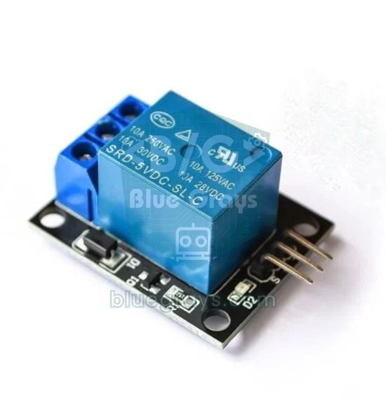
Most 1, 2, 4 and 8-channel relay modules on the market have a PC817 on each channel's input. Current from the VCC pin passes through a resistor and an indicator LED to the optocoupler's LED; when the IN pin is pulled LOW the circuit is completed and the relay clicks on. That's why these modules usually work active LOW. However, as shipped from the factory the JD-VCC jumper is fitted and the relay coil is fed from the same VCC and GND: the optocoupler is there, but there's no isolation. You can find the basics of relay modules in the What Is a Relay Module? post.
| Setting | Wiring | Isolation |
|---|---|---|
| JD-VCC jumper fitted | Arduino 5V → VCC, GND → GND, pin → IN | None; noise from the relay coil gets into the Arduino's supply |
| Jumper removed | Arduino 5V → VCC, pin → IN; Arduino GND not connected. Separate 5 V supply → JD-VCC and GND | Full; the only thing the two sides share is the light inside the optocoupler |
A note on driving a triac with the MOC3021
If you want a silent, spark-free AC switch instead of a relay, you use a triac (e.g. BT136) and a triac-output optocoupler to drive it. The MOC3021 is random-phase: it fires the triac the moment the LED lights, so together with a zero-cross detector it suits building a dimmer. The MOC3041 and MOC3063 are models with a zero-crossing circuit; they only fire as the voltage passes through zero, produce less interference in on/off applications, but can't be used for dimming. The MOC3021's LED may need up to 15 mA to trigger; at 5 V, 220 Ω (about 17 mA) is a suitable value, while 330 Ω may not be enough for some parts. As in the datasheets, a resistor of about 360 Ω goes between the triac gate and the MOC3021, and for inductive loads like motors an RC snubber is added across the triac. Ready-made SSR (solid-state relay) modules contain exactly this structure.
Optocoupler project ideas
- Industrial sensor reader: count products on a conveyor with a 24 V inductive proximity sensor and show the count on an LCD.
- Car ignition detector: wake the ESP32 when the ignition is switched on and start the car camera or a logger.
- Power outage alarm: with a ready-made AC sensing module, sound a buzzer or send a notification to your phone when the mains goes off.
- Doorbell catcher: read the existing 12 V doorbell line with isolation and send a notification when it rings.
- Isolated relay board: control a 230 V lamp with a relay module whose JD-VCC jumper you've removed and which you power from a separate supply.
- MIDI input: read MIDI notes from an electronic instrument on the Arduino with a 6N138.
Common mistakes and how to fix them
| Symptom | Likely cause | Fix |
|---|---|---|
| The output never changes | LED connected backwards, or connected without a resistor and burnt out | Check that pin 1 is the one marked with a dot; test the LED on the multimeter's diode range |
| The logic works inverted | The pin goes LOW when voltage is present; this is normal | Treat LOW as "present" in the code |
| The output doesn't go fully LOW (stays at 1–2 V) | LED current too low, CTR insufficient or pull-up too small | Reduce the LED resistor or increase the pull-up (e.g. 10 kΩ) |
| The PWM signal gets distorted | The PC817 is too slow above a few kHz | Reduce the pull-up or use a fast optocoupler such as the 6N137 |
| The Arduino resets despite isolation | The GNDs of the two sides have been joined | Separate the input side's GND from the Arduino; remove the JD-VCC jumper on the relay module |
| Random false triggers | Long cable, noise, contact bounce | Debounce in software, shorten the cable, add a 100 nF capacitor across the LED |
An optocoupler is the cheapest way to take an Arduino project off your desk and let it talk safely to the real world's 12 V, 24 V and 230 V signals: a part that costs pennies separates your board and your computer from high voltage. In the BlueGrays app you'll find the projects for controlling a 230 V bulb with a relay, smart lighting and irrigation, step by step with circuit diagrams and code.
Frequently asked questions
What is an optocoupler used for?
An optocoupler carries a signal between two circuits with light, without any electrical connection. This isolates a high-voltage or noisy circuit from a sensitive microcontroller like the Arduino. It's used for reading industrial sensors, in relay modules and in mains sensing circuits.
What is the PC817 pinout?
The PC817 has four legs: pin 1 at the dotted corner is the LED anode and pin 2 is the cathode. On the opposite side, pin 3 is the phototransistor's emitter and pin 4 is its collector.
What resistor should I use with an optocoupler?
The resistor is found with R = (supply voltage − 1.2 V) / LED current. Good starting values are 330 Ω for an Arduino 5 V pin, 220 Ω for an ESP32, 2.2 kΩ for a 12 V signal and 4.7 kΩ for a 24 V signal.
What is CTR in an optocoupler?
CTR (current transfer ratio) is the ratio of the current the output transistor can pass to the LED current. In an optocoupler with 100% CTR, 5 mA through the LED lets you draw at most about 5 mA from the output. Always design around the lowest CTR in the datasheet.
What is the difference between the PC817 and the 4N35?
Both are phototransistor-output optocouplers. The PC817 has four legs and is cheap, with a CTR of 50–600% depending on its rank. The 4N35 has six legs, brings out the base pin and withstands collector voltages up to 70 V.
Can an optocoupler detect 230 V mains?
Yes, AC-input optocouplers such as the H11AA1 with suitably rated series resistors can detect mains voltage and zero crossings. But mains voltage can kill; if you're not experienced, use ready-made, enclosed AC sensing modules.
Projects to build after reading this
See all projects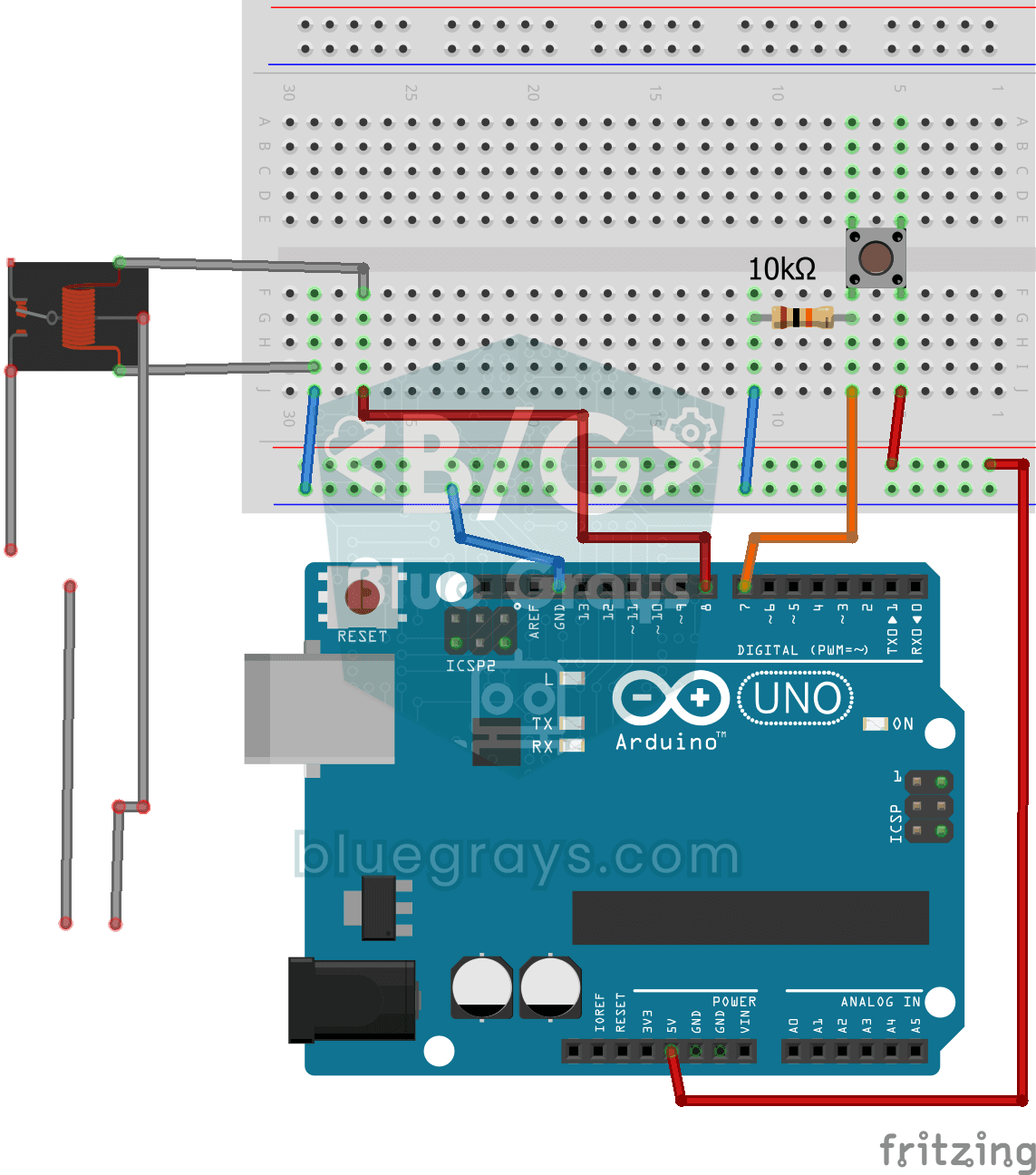
Lighting 220V Bulb with Push Button
As long as you hold the button, a real 220-volt bulb stays lit, and it goes out the moment you let go. The Arduino's tiny signal cannot light the bulb directly, so a relay, an electrically controlled
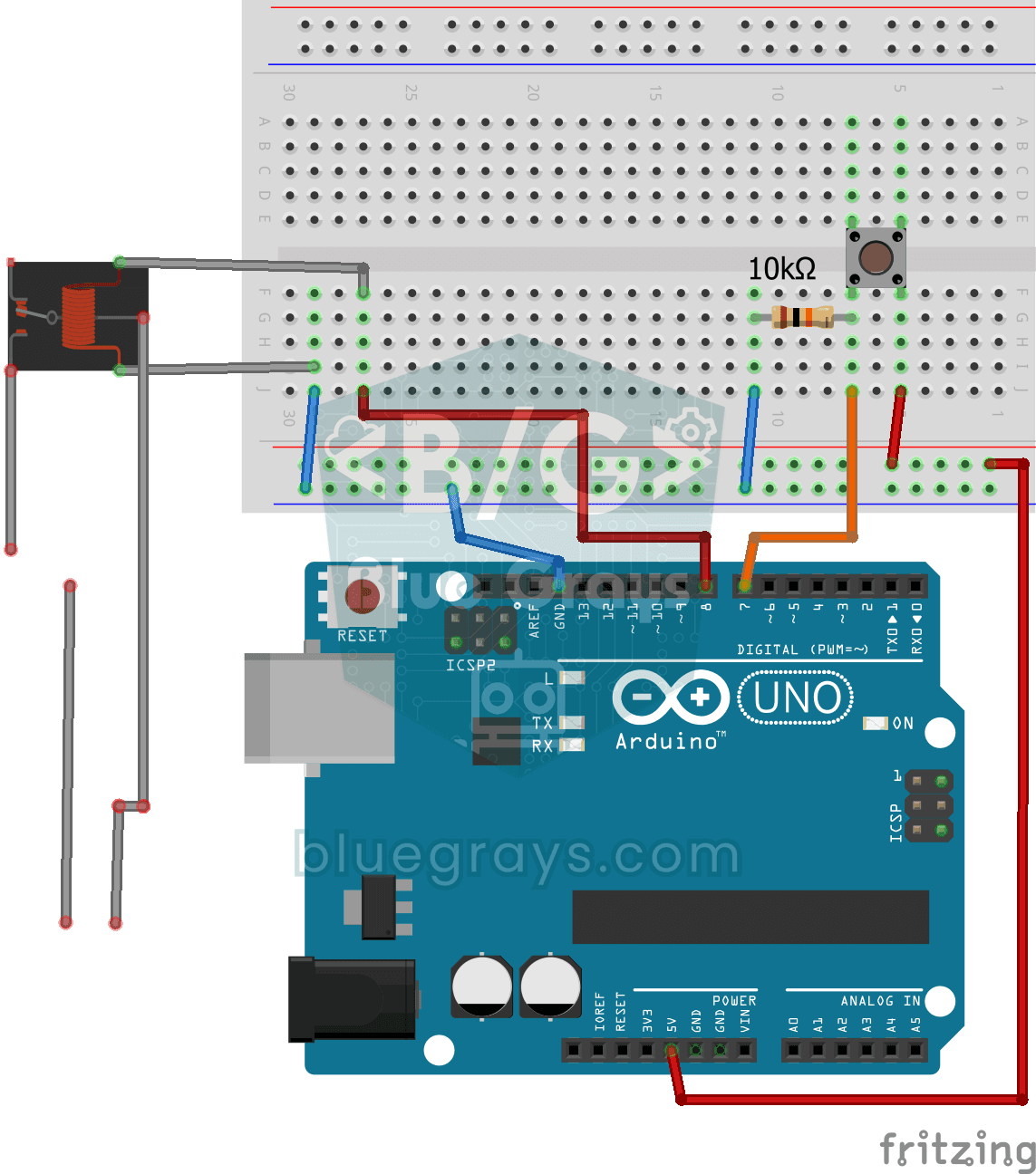
Lighting 220V Bulb with Button (On-Off)
Want to switch a real household bulb on and off with a tiny button? Each time you press the button, the Arduino flips a relay and the bulb lights up; press again and it goes off. The relay is a go-bet
Lighting 220V Bulb with Remote Control
Switch a real light bulb in your home on and off with a TV remote, without getting up from the sofa. The Arduino reads the invisible light signal from the remote; the power button clicks the relay and

Smart Stair and Corridor Lighting
Step onto the stairs or into the hallway and the lights come on one step at a time in the direction you are walking. There is a distance sensor at each end; whichever one you pass, the eight LEDs ligh

ESP32 Smart Lighting (PIR + LDR + Relay + OLED)
Turn your hallway, bathroom, or pantry into smart lighting with ESP32! Using a PIR motion sensor, LDR light sensor, and a relay module, we build the classic "light turns on when motion is detected in the dark" scenario — if the environment is already bright, motion does NOT trigger the light, saving energy during the day. The light stays on for 30 seconds; if motion continues, the timer resets and the light stays on longer. The SSD1306 OLED shows large-font status (ON / DAYTIME / WAITING), a cou

Smart Irrigation Station
A gardener that waters your plants on its own, so they don't dry out while you're on vacation. A soil moisture sensor measures how wet the soil is; when it gets dry, the Arduino runs the water pump fo

Automatic Lighting with the ESP32 PIR Motion Sensor
In this project, we will use the HC-SR501 PIR motion sensor to detect when someone enters the room and automatically turn on the LED. We will track how long the LED stays on using millis(); each HIGH reading from the sensor will update the last motion time, and the LED will turn off at least 10 seconds after the last HIGH reading. The current code also waits 50 ms in each loop with delay(50), so the application loop is not fully non-blocking. In real-life applications, it can be used for sta