
Arduino Block Coding: Blink an LED with Blocks and C++ Side by Side
Arduino block coding for beginners: wire an LED with a 220 Ω resistor, see the C++ line behind every block, change the 100 ms wait, then build a traffic light.
With Arduino block coding, the first program is almost always the same: blink an LED. In this post we do it from start to finish. We wire an LED to pin 9 through a 220 Ω resistor, read the blocks of the LED Blink project in BlueGrays one by one, and see side by side which line of the C++ code uploaded to the board each block turns into. You'll also try changing a single number, the 100 in the "wait 100 ms" block, to control how fast the LED blinks.
We won't stop at one LED. We'll grow the same logic step by step into programs that blink two LEDs in turn, behave like a traffic light and flash like police lights. Then you'll see the same idea on the ESP32 and on the Raspberry Pi Pico with MicroPython. At the end there's a table of the mistakes almost every beginner makes once. Every project in this post is free in BlueGrays, blocks and code included, and you can browse all projects with blocks by platform on the block coding page.
What do you need?
| Part | Qty | Note |
|---|---|---|
| Arduino Uno (or Nano) | 1 | Connects to your computer over USB |
| 5 mm LED (red is easiest) | 1 | Long leg +, short leg - |
| 220 Ω resistor | 1 | Colour bands: red, red, brown |
| Breadboard | 1 | No soldering needed |
| Male-to-male jumper wires | 2 | For D9 and GND |
| Computer with the Arduino IDE | 1 | To upload the code to the board |
The circuit: connecting the LED to pin 9
An LED has two legs and its direction matters. The long leg is the anode (+) and the short leg is the cathode (-); on the cathode side the plastic body has a flat edge. Current only flows from anode to cathode, so if you put the LED in backwards nothing happens. Connect Arduino pin 9 to one end of the 220 Ω resistor and the other end of the resistor to the LED's long leg. Then take the short leg to GND. The resistor limits the current: take the roughly 2 V a red LED needs away from 5 V and 3 V is left across the resistor, and 3 V / 220 Ω is about 14 mA. That's comfortable for the LED and safe for the Arduino pin. You can check the value for your own LED colour with the LED resistor calculator. How an LED works is covered in what is an LED, and how breadboard rows are connected inside in what is a breadboard.
| Connection | Arduino Uno (LED Blink) | ESP32 (LED Blink with ESP32) | Raspberry Pi Pico (external LED) |
|---|---|---|---|
| LED long leg (anode, +) | D9 through 220 Ω | GPIO 5 through 220 Ω | GP14 through 220 Ω |
| LED short leg (cathode, -) | GND | GND | GND |
| Pin in the blocks and code | 9 | 5 | LED_PIN = 14 |
| Wait in the project | 100 ms | 500 ms | 0.5 seconds |
| Pin voltage | 5 V | 3.3 V | 3.3 V |
Your first program in blocks: LED Blink
Once the circuit is ready, let's look at the program. Open the LED Blink project in BlueGrays and switch on Show as blocks in the code section, and you'll see the blocks below. There are seven blocks in total, split into two big groups: setup (runs once) at the top and loop forever underneath. Blocks appear in the app's language, so in English they read "write HIGH to pin", while in Turkish the same block reads "numaralı pine YÜKSEK yaz".
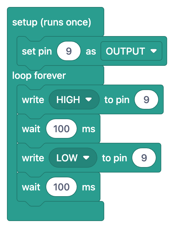
The blocks inside setup (runs once) run only once, when the board powers up or you press reset. There's a single block here: "set pin 9 as OUTPUT". Arduino's digital pins can be inputs or outputs. Since we're driving an LED, we're telling the board "I'll be sending power out of this pin". The loop forever group starts after setup finishes and runs from top to bottom again and again as long as the board is on. Its four blocks turn the LED on, wait 100 milliseconds, turn it off and wait another 100 milliseconds. After the last block the program jumps back to the top and the LED lights again. What we call blinking is simply these four steps repeating five times a second.
Block → C++ line: what does each block become?
| Block | C++ line | What it does |
|---|---|---|
| setup (runs once) | void setup() { ... } | Runs what's inside once at power-up |
| set pin 9 as OUTPUT | pinMode(9,OUTPUT); | Makes pin 9 an output |
| loop forever | void loop() { ... } | Repeats what's inside forever |
| write HIGH to pin 9 | digitalWrite(9,HIGH); | Puts 5 V on the pin, the LED lights |
| wait 100 ms | delay(100); | Pauses the program for 0.1 s |
| write LOW to pin 9 | digitalWrite(9,LOW); | Sets the pin to 0 V, the LED turns off |
| wait 100 ms | delay(100); | Stays off for 0.1 s |
1// Led Yakma (proje 1): D9'daki LED 100 ms yanar, 100 ms söner
2// LED Blink (project 1): the LED on D9 is on for 100 ms, off for 100 ms
3void setup() {
4  pinMode(9,OUTPUT);     // LED pini çıkış / LED pin as output
5}
6
7void loop() {
8  digitalWrite(9,HIGH);  // LED'i yak / turn the LED on
9  delay(100);            // 100 ms bekle (1000 ms = 1 s) / wait 100 ms (1000 ms = 1 s)
10  digitalWrite(9,LOW);   // LED'i söndür / turn the LED off
11  delay(100);            // 100 ms bekle / wait 100 ms
12}
13
Put the table next to the code and you can see what the blocks handle for you. The shape of the setup and loop forever groups matches the curly braces of the void setup() and void loop() functions: the group a block sits in decides which pair of braces its line is written inside. With blocks you don't have to think about the semicolon at the end of each statement, upper and lower case (pinMode, digitalWrite) or brackets. Once you start editing the code yourself in the Arduino IDE, though, they matter; a single missing semicolon is enough for a compile error. That's the real benefit of blocks: you get the logic of the program straight first, then learn how that same logic is written in code.
What happens if you change "wait 100 ms"?
The wait time is in milliseconds (ms), and 1000 ms equals one second. Both wait blocks in the project are 100 ms, so the LED stays on for 0.1 seconds and off for 0.1 seconds. One full cycle takes 200 ms, which means the LED blinks five times a second. Increase the number in both blocks and the LED slows down; decrease it and it speeds up. Below a certain point your eye can no longer tell the blinks apart and the LED looks like it's on all the time. The table shows what you'll see when you change the two waits:
| Wait blocks | One full cycle | Blinks per second | What you see |
|---|---|---|---|
| 10 ms + 10 ms | 20 ms | 50 | Looks steadily on, a little dimmer |
| 100 ms + 100 ms (project value) | 200 ms | 5 | Fast, clear blinking |
| 250 ms + 250 ms | 500 ms | 2 | Easy-to-follow blinking |
| 500 ms + 500 ms | 1 s | 1 | Once a second, a calm rhythm |
| 1000 ms + 1000 ms | 2 s | 0.5 | On for 1 second, off for 1 second |
| 100 ms + 900 ms | 1 s | 1 | Short flash, long darkness |
Growing the program: two LEDs, a traffic light, police lights
Once you can blink one LED, you don't need anything new to control several; you just repeat the same three blocks with different pins. In the Two LEDs Blinking Alternately project, two pins are made outputs in setup: 8 and 9. Inside loop forever come "write HIGH to pin 8" and "write LOW to pin 9", then "wait 200 ms". Then the opposite is written and the program waits 200 ms again. The trick is that the two write blocks run back to back with no wait in between, so the two LEDs seem to swap at the same moment. The wait block decides how long each state lasts.
The Traffic Light project takes the same idea to three LEDs: red on D2, yellow on D3, green on D4. The loop forever group has four phases and each follows the same pattern: one write HIGH or write LOW block for each of the three LEDs, then one wait block. The write blocks decide which LED stays on and the wait block decides for how long. More blocks don't make it harder, just longer. A version closer to a real junction, with a pedestrian button, is in the Arduino traffic light post.
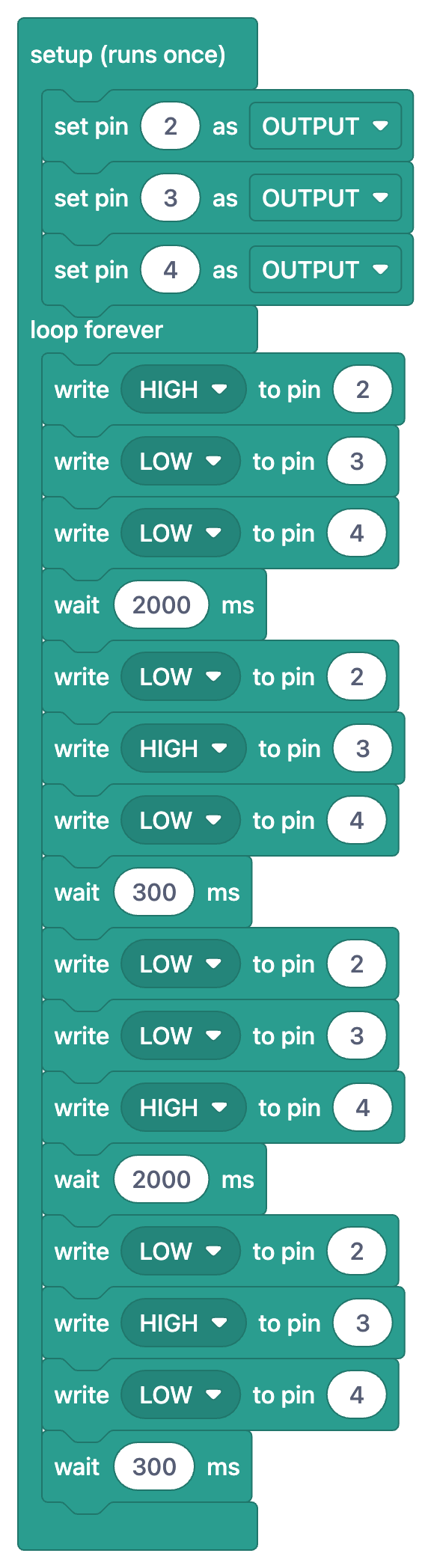
| Phase | Red (D2) | Yellow (D3) | Green (D4) | Wait |
|---|---|---|---|---|
| 1 | HIGH | LOW | LOW | 2000 ms (2 s) |
| 2 | LOW | HIGH | LOW | 300 ms |
| 3 | LOW | LOW | HIGH | 2000 ms (2 s) |
| 4 | LOW | HIGH | LOW | 300 ms |
1// Trafik Lambası (proje 3) / Traffic Light (project 3)
2void setup() {
3  pinMode(2,OUTPUT);    // Kırmızı / Red
4  pinMode(3,OUTPUT);    // Sarı / Yellow
5  pinMode(4,OUTPUT);    // Yeşil / Green
6}
7
8void loop() {
9  // Kırmızı yanar, 2 s bekle / Red on, wait 2 s
10  digitalWrite(2,HIGH);
11  digitalWrite(3,LOW);
12  digitalWrite(4,LOW);
13  delay(2000);
14  // Sarı yanar, 0,3 s bekle / Yellow on, wait 0.3 s
15  digitalWrite(2,LOW);
16  digitalWrite(3,HIGH);
17  digitalWrite(4,LOW);
18  delay(300);
19  // Yeşil yanar, 2 s bekle / Green on, wait 2 s
20  digitalWrite(2,LOW);
21  digitalWrite(3,LOW);
22  digitalWrite(4,HIGH);
23  delay(2000);
24  // Sarı yanar, sonra başa (kırmızıya) dön / Yellow on, then back to red
25  digitalWrite(2,LOW);
26  digitalWrite(3,HIGH);
27  digitalWrite(4,LOW);
28  delay(300);
29}
30
The LED Police Lights project introduces two new kinds of block. The first is the global variables (at the top) group with the block "declare integer (int) delayTime = 60" inside. That's the line int delayTime = 60; in the code, and it gives the flash time a name. Because the wait blocks use delayTime instead of a number, you change the speed by editing just the 60, not four separate blocks. The second is the green "repeat 3 times" block; it runs the four blocks inside it three times and becomes the loop for(int i=0;i<3;i++) in C++.
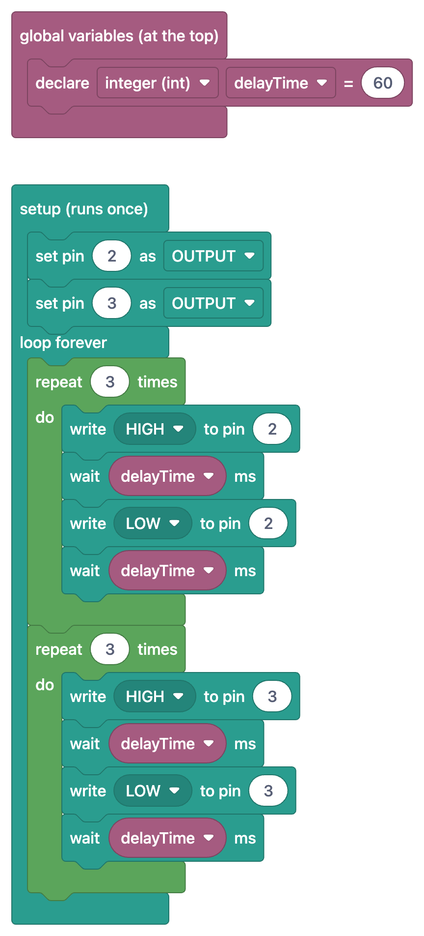
Let's do the maths: on each flash the red LED is on for 60 ms and off for 60 ms, so one flash takes 120 ms. Three flashes make 360 ms, and the same goes for the blue LED. A full cycle takes about 0.7 seconds. Set delayTime to 30 and the lights flash twice as fast; set it to 120 and they slow down. Variables and loops are the topic of part 4 of the series, where we cover them in detail in "loop forever", count and array blocks. The LED Chaser project, which runs the light along a row of LEDs, is the next step on the same path.
The same idea on the ESP32 and Raspberry Pi Pico
On the ESP32 the blocks are almost identical to the Arduino ones, because the ESP32 is also programmed in C++ with the Arduino IDE. In the LED Blink with ESP32 project the LED is on GPIO 5 and the wait blocks are 500 ms. The code lines are the same too: pinMode(5, OUTPUT); digitalWrite(5, HIGH); delay(500);. The only differences are the pin number, the fact that ESP32 pins output 3.3 V, and selecting an ESP32 board in the Arduino IDE. Everything you learn on the Uno carries straight over to the ESP32.
In Raspberry Pi Pico projects the blocks turn into MicroPython code and the block names change a little. In the Pico external LED project the LED is on GP14. The "pin led : GP LED_PIN, OUTPUT" block matches led = Pin(LED_PIN, Pin.OUT), "turn on (on) pin led" matches led.on(), "wait 0.5 seconds" matches time.sleep(0.5), and loop forever matches the while True: loop. Note that in MicroPython the wait is in seconds, not milliseconds; Arduino's delay(500) becomes time.sleep(0.5). If you want to try it without any wiring, the Pico onboard LED project lights the LED on GP25 on the board itself; on a Pico W the onboard LED is accessed by the name "LED" instead of GP25.
1# Pico harici LED (proje 8163), seri port satırları çıkarıldı
2# Pico external LED (project 8163), serial print lines removed
3from machine import Pin
4import time
5
6LED_PIN = 14                    # GP14, herhangi bir boş GPIO / any free GPIO
7led = Pin(LED_PIN, Pin.OUT)     # pini çıkış yap / set the pin as output
8
9while True:                     # sürekli tekrarla / loop forever
10    led.on()                    # LED'i yak / turn the LED on
11    time.sleep(0.5)             # 0,5 saniye bekle / wait 0.5 s
12    led.off()                   # LED'i söndür / turn the LED off
13    time.sleep(0.5)
14
Common mistakes and how to fix them
| Mistake | Symptom | Fix |
|---|---|---|
| LED inserted backwards | The LED never lights | Long leg to the pin via the resistor, short leg to GND; turn the LED around |
| No resistor | LED too bright, gets hot, may fail quickly | Put a 220 Ω resistor in series with the LED |
| Pin in the block differs from the circuit | Upload works, but the LED stays dark | The 9 in the block and the D9 you wired must match; change either the wire or the number |
| Second wait block forgotten | The LED looks permanently on | There must also be a wait block (delay) after the write LOW block |
| Wait too short (e.g. 5 ms) | LED looks steady and slightly dim | Try at least 50–100 ms |
| Both LED legs in the same breadboard row | The LED never lights | Put the legs in different rows; holes in the same row are connected inside |
| Wrong board or port selected | The Arduino IDE shows an upload error | Pick the right board and port from the Tools menu |
Step by step in the app: from blocks to the board
- In BlueGrays, open the LED Blink project, which has the blocks badge in the project list. You can also use the filter to show only projects with blocks.
- Following the circuit diagram, place the LED, the 220 Ω resistor and two wires on the breadboard.
- In the code section, switch on Show as blocks. The blocks replace the code; tap the image to open it full screen.
- Go to the Understand the blocks tab. The program is explained step by step, and each step shows only its own blocks and what they do.
- Switch the toggle off to get back to the real code, copy it and paste it into the Arduino IDE. Blocks aren't uploaded to the board directly; it's always this code that goes onto it.
- In the Arduino IDE, select Arduino Uno as the board, pick the right port and press Upload. If you haven't installed the IDE yet, the Arduino IDE setup post walks you through it.
- Once the LED is blinking, change both delay(100) lines to delay(1000), upload again and see the difference for yourself.
In this post the LED always blinked to the same rhythm; the program never listened to the outside world. The next step is letting the board make decisions: part 3 of the series, the button and the "if" block, covers a program that lights the LED when you press a button and how the "if" block turns into if/else in C++.
In the BlueGrays app you can look at LED Blink, Two LEDs Blinking Alternately, Traffic Light, LED Police Lights and the LED projects for ESP32 and Pico with their circuit diagrams and code, switch to the block version of the same program with Show as blocks, and read what each step does with Understand the blocks.
Frequently asked questions
What is Arduino block coding?
It's a way of showing an Arduino program as blocks that snap together like puzzle pieces instead of typed text. Each block, such as "write HIGH to pin 9" or "wait 100 ms", matches one line of the C++ code uploaded to the board. With no semicolons or brackets to worry about, beginners can focus on the program's logic first.
How do you blink an LED with block coding?
Put "set pin 9 as OUTPUT" in the setup group, and "write HIGH to pin 9", "wait 100 ms", "write LOW to pin 9" and "wait 100 ms" in the loop forever group. In the circuit the LED goes to D9 through a 220 Ω resistor. These blocks become the pinMode, digitalWrite and delay lines.
Why is my LED always on instead of blinking?
The most common reason is a missing wait block after the write LOW block. The LED is then off for only microseconds and your eye can't notice it. If the waits are very short (for example 5 ms) the LED also looks steadily on; try 100 ms or more.
What resistor should I use for an LED on Arduino?
On the 5 V pins of an Arduino Uno, 220 Ω is the most common choice and lets about 14 mA flow through a red LED. 330 Ω works too, with a slightly dimmer LED. The resistor limits the current whichever LED leg it's on; what matters is that it's in series.
Can I upload the blocks directly to the Arduino?
No. The blocks in BlueGrays make the program easier to read and understand; the board always gets the project's real code. You copy that code into the Arduino IDE (Thonny for the Pico) and upload it from there.
How many seconds is 1000 ms, and how do I change the blink speed?
1000 milliseconds is 1 second. A bigger number in the wait blocks slows the LED down, a smaller one speeds it up: with both blocks at 100 ms the LED blinks 5 times a second, at 500 ms once a second. In the Pico's MicroPython blocks the time is written in seconds, so 0.5 is half a second.
Projects to build after reading this
See all projects
LED Blink
The very first hello of electronics: switching a single LED on and off. The Arduino turns the LED on and off at short intervals, so the light blinks quickly. You see in the simplest way how the board

Two LEDs Blinking Alternately
Two LEDs blink quickly in turn: when one lights up the other goes off, as if they were tossing a ball back and forth. The Arduino keeps each light on for a fifth of a second and then hands over to the

Traffic Light
A tiny copy of the traffic light you see on the road every day. Red stays on for two seconds, yellow flashes for a moment, green stays on for two seconds, then it goes back to red through yellow again

LED Police Lights
Just like the lights on a police car: the red LED flashes three times in quick succession, then the blue LED flashes three times, and the pattern keeps repeating without a break. All you need is two L

LED Chaser
Lights that switch on one after another, as if they were running. The Arduino lights six LEDs one at a time; each glows for a brief moment and goes out, so the light walks from start to end and then s

LED Blink with ESP32
Teaches basic GPIO output usage with ESP32. We achieve a blinking effect by turning an LED on and off from a digital pin. ESP32 version of the classic blink project on Arduino UNO; the basic blink commands in the Arduino environment are the same, but the ESP32's pin layout and 3.3 V GPIO levels differ from those of the Arduino UNO.

ESP32 Traffic Light
Real traffic light simulation with 3 LEDs red-yellow-green. Timings close to real traffic logic: red long, yellow short, green long. Classic example of sequential GPIO control.
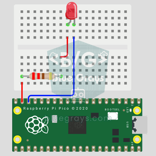
Raspberry Pi Pico: Controlling an External LED (Breadboard)
The next step after Pico’s built-in LED: connecting an external LED to the breadboard and controlling it via the GP14 pin. In this project, you’ll learn how to use any of the Pico’s general-purpose GPIO pins as an output, the LED’s polarity (long leg = anode/+, short leg = cathode/–), and why a current-limiting resistor (220Ω) is required. If you don’t include the resistor, excessive current will flow through the LED and it may burn out. The circuit is very simple: Pico GP14 → 220Ω resistor → LE