
Arduino Metal Detector: Search Coil, LC Oscillator and Code
Build an Arduino metal detector: wind the search coil, LC oscillator, frequency shift, buzzer tones, a coil turns table, ground effect and Uno and ESP32 code.

An Arduino metal detector is a project you can build in an afternoon from a search coil, a cheap chip and a handful of passive parts, and it teaches you a lot along the way. The coil is part of an LC oscillator; when metal comes near it, the coil's inductance changes, the oscillator's frequency shifts, and the Arduino measures that shift and turns it into sound through a buzzer. A detector like this picks up a coin at a few centimetres, a drinks can at 10–15 cm and a large metal lid at 20–30 cm. It won't compete with a commercial detector, but it's enough to find a nail in the wall, keys in the sand or a tool lost in the garden.
In this guide we'll first look at how metal detectors work and compare the three basic methods: frequency shift, VLF and pulse induction. Then we'll wind the search coil, see in a table how the number of turns affects sensitivity, build the LC oscillator and write the code for an Arduino Uno and an ESP32. The last sections cover calibration, ground effects, telling iron from other metals and the most common problems.
How does a metal detector work?
A coil carrying alternating current creates a magnetic field around it that keeps changing direction. When a metal object enters that field, one of two things happens. In metals with no iron in them, such as aluminium, copper, brass, gold and silver, the field drives eddy currents around inside the object; those currents create a field that opposes the coil's, the coil's effective inductance drops and the oscillator frequency rises. Magnetic metals like iron and steel, on the other hand, gather the field lines into themselves; at low frequencies this effect wins, the inductance goes up and the frequency falls. So the direction of the shift also tells you whether the metal is iron or not.
The effect fades very quickly with distance. For a small object some way from the coil, the frequency shift drops roughly with the sixth power of the distance: move the object twice as far away and the signal falls to about 1/64. That's why, in a home-made detector, depth is set not by the code but by the size of the coil and the stability of the oscillator. These are the three basic methods detectors use:
| Method | How it works | Depth | Tells iron apart | Ground effect | Difficulty |
|---|---|---|---|---|---|
| Frequency shift (BFO type) | Measures the frequency change of a single-coil oscillator | Shallow | Yes (from the direction of the shift) | Noticeable on mineralised ground | Easy, the method in this guide |
| VLF (induction balance) | Separate transmit and receive coils; measures the phase difference | Medium to good | Very well | Ground balance is possible | Medium to hard |
| Pulse induction (PI) | Pulses the coil and measures how long the decay lasts after switch-off | Best | Poorly | Good even on mineralised soil and beach sand | Hard |
In pulse induction detectors the coil produces a flyback voltage of hundreds of volts after every pulse; it has to be damped safely, sampled within microseconds and processed with a fast comparator or op-amp. For a first project that's both risky and hard to debug. So we use the frequency-shift method: one coil, one chip, low voltage and a job the Arduino already does well, counting pulses.
What you need
- An Arduino Uno (or an ESP32 development board).
- A 74HCU04 or CD4069UB hex inverter chip. The unbuffered versions (with the U) are more stable in an oscillator; a 74HC04 usually works too.
- Two 10 nF film capacitors (polyester or polypropylene). X7R ceramic capacitors change a lot with temperature and make the frequency drift.
- 1 MΩ, 470 Ω and 220 Ω resistors and a 100 nF decoupling capacitor.
- 0.4 mm enamelled copper wire (magnet wire), about 30 m for a 15 cm, 60-turn coil.
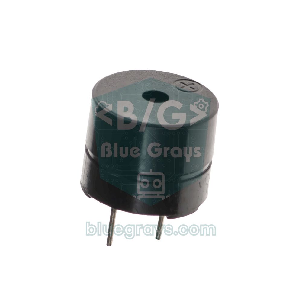
- A passive buzzer, an LED and a push button.
- A plastic or wooden frame for the coil, a two-core cable and, optionally, aluminium foil and insulating tape.
Winding the search coil
- Find a former about 15 cm across: a plastic bucket lid, a cardboard tube or nails hammered into a board in a circle all work.
- Wind 60 tight, even turns of enamelled wire around the former and leave 15–20 cm of wire at each end.
- Before taking the winding off the former, wrap it firmly with insulating tape every 3–4 cm; if the wires move against each other, the inductance changes and the detector beeps by itself.
- Strip the enamel from the wire ends with sandpaper or a lighter and measure the resistance with a multimeter: a 15 cm, 60-turn coil should read around 3–5 Ω.
- If you like, cover the winding with tape and wrap it in aluminium foil, but leave a 1 cm gap between the two ends of the foil; touch a bare wire to the foil and take it to the circuit's GND.
- Fix the coil to a handle with no metal parts, twist the two-core cable and tape it along the handle.
Coil turns and sensitivity table
The oscillator frequency is given by f = 1 / (2π√(L·C)). In our circuit the two 10 nF capacitors act as if they were in series, so C = 10 × 10 / (10 + 10) = 5 nF. The inductance of a round air-core coil grows roughly with the square of the number of turns and with the coil's diameter. The table gives calculated values for coils wound with 0.4 mm wire and the rough detection distances to expect on dry ground:
| Coil diameter | Turns | Inductance (approx.) | Frequency (C = 5 nF) | Coin | Drinks can | Note |
|---|---|---|---|---|---|---|
| 10 cm | 40 | 350 µH | 120 kHz | 3–5 cm | 8–12 cm | Sensitive to small objects; frequency high for the ESP32 |
| 10 cm | 60 | 750 µH | 82 kHz | 3–5 cm | 8–12 cm | Compact hand-held detector |
| 15 cm | 40 | 600 µH | 93 kHz | 4–7 cm | 12–18 cm | Less wire, a good start |
| 15 cm | 60 | 1.25 mH | 63 kHz | 4–7 cm | 12–18 cm | The coil in this guide; suits the Uno and ESP32 |
| 20 cm | 30 | 500 µH | 100 kHz | 4–7 cm | 15–22 cm | Deeper on large objects |
| 20 cm | 50 | 1.3 mH | 63 kHz | 4–7 cm | 15–22 cm | Heavy, but sweeps a wide area |
Two lessons come out of the table. First, the number of turns hardly changes depth; its main job is setting the frequency. Fewer turns mean a higher frequency, and a higher frequency is a little more sensitive to small non-ferrous objects. Second, a big coil sees big objects from further away, but gains little on small ones like a coin, because a small object disturbs only a tiny part of its field. 15 cm and 60 turns is a balanced choice for a first detector. We cover coils and inductance calculations in depth in our what is an inductor guide, and the inductor code tool helps you decode ready-made inductors.
The circuit: LC oscillator and connections
We use the chip's first inverter gate as the oscillator. The 1 MΩ feedback resistor keeps the gate in its linear region, and the coil with the two capacitors forms a π network. At the resonant frequency that network shifts the signal by 180 degrees; added to the inverter's own 180 degrees, the circuit oscillates at exactly that frequency. The second inverter gate turns the near-sine signal into a clean 0–5 V square wave and sends it to the Arduino.
| Connection | Goes to | Note |
|---|---|---|
| 74HCU04 pin 14 (VCC) | 5V | 100 nF capacitor to GND right at the pin |
| 74HCU04 pin 7 (GND) | GND | Common ground with the Arduino |
| Pin 1 (1st inverter input) | Coil end A, C1 (10 nF) to GND, 1 MΩ to pin 2 | Oscillator input |
| Pin 2 (1st inverter output) | Through 470 Ω to point B, and directly to pin 3 | Oscillator output |
| Point B | Coil end B, C2 (10 nF) to GND | Second leg of the π network |
| Pin 4 (2nd inverter output) | Uno: D5; ESP32: GPIO 34 through 10 kΩ, plus 20 kΩ from GPIO 34 to GND | 0–5 V square wave |
| Pins 5, 9, 11, 13 | GND | Unused inputs are never left floating |
| Passive buzzer | Uno: D8, ESP32: GPIO 25; other end to GND | Sound with tone() |
| LED | Uno: D13, ESP32: GPIO 2; through 220 Ω | Detection indicator |
| Zero button | Uno: between D2 and GND; ESP32: the board's BOOT button (GPIO 0) | Re-measures the baseline |
Arduino Uno code: counting the frequency and making sound
The Uno's 16-bit Timer1 can count the pulses arriving on pin D5 directly in hardware, so the processor doesn't have to deal with each one. The code counts pulses for 200 ms, multiplies the result by 5 to get hertz and compares it with the baseline frequency measured with no metal nearby. If the frequency dropped, it plays a low tone; if it rose, a high one, and the bigger the shift, the higher the pitch.
1// Arduino Uno metal dedektörü (frekans kayması yöntemi)
2// Arduino Uno metal detector (frequency-shift method)
3// Osilatör çıkışı D5'e: Timer1 bu pindeki darbeleri sayar / oscillator output to D5: Timer1 counts its pulses
4
5const byte BUZZER_PIN = 8;          // pasif buzzer / passive buzzer
6const byte LED_PIN = 13;            // algılama LED'i / detection LED
7const byte ZERO_PIN = 2;            // sıfırlama butonu, GND'ye / re-zero button to GND
8const unsigned int GATE_MS = 200;   // ölçüm penceresi / gate time
9const float THRESHOLD_HZ = 15.0;    // bu kadar sapma metal demek / this much shift means metal
10
11float baseline = 0;                 // metal yokken frekans / frequency with no metal nearby
12float smoothDiff = 0;               // yumuşatılmış fark / smoothed difference
13
14// GATE_MS boyunca D5'teki yükselen kenarları sayar / counts rising edges on D5 during GATE_MS
15unsigned long countPulses() {
16  TCCR1A = 0;
17  TCCR1B = 0;
18  TCNT1 = 0;
19  TIFR1 = _BV(TOV1);                                // taşma bayrağını temizle / clear the overflow flag
20  TCCR1B = _BV(CS12) | _BV(CS11) | _BV(CS10);       // saat kaynağı T1, yükselen kenar / clock from T1, rising edge
21  delay(GATE_MS);
22  TCCR1B = 0;                                       // sayacı durdur / stop the counter
23  unsigned long n = TCNT1;
24  if (TIFR1 & _BV(TOV1)) n += 65536UL;              // bir taşma olduysa ekle / add one overflow
25  return n;
26}
27
28float readFrequency() {
29  return countPulses() * (1000.0 / GATE_MS);        // Hz
30}
31
32void calibrate() {
33  noTone(BUZZER_PIN);
34  digitalWrite(LED_PIN, HIGH);
35  float sum = 0;
36  for (int i = 0; i < 8; i++) sum += readFrequency();  // 8 ölçümün ortalaması / average of 8 readings
37  baseline = sum / 8;
38  smoothDiff = 0;
39  digitalWrite(LED_PIN, LOW);
40  Serial.print(F("Taban frekans / Baseline (Hz): "));
41  Serial.println(baseline);
42}
43
44void setup() {
45  Serial.begin(115200);
46  pinMode(5, INPUT);                                // T1 girişi / T1 input
47  pinMode(BUZZER_PIN, OUTPUT);
48  pinMode(LED_PIN, OUTPUT);
49  pinMode(ZERO_PIN, INPUT_PULLUP);
50  delay(500);                                       // osilatör otursun / let the oscillator settle
51  calibrate();
52}
53
54void loop() {
55  if (digitalRead(ZERO_PIN) == LOW) calibrate();    // butona basınca sıfırla / re-zero on button press
56
57  float f = readFrequency();
58  float diff = f - baseline;
59  smoothDiff = smoothDiff * 0.6 + diff * 0.4;       // gürültüyü azalt / reduce noise
60
61  Serial.print(F("diff:"));                         // Seri Çizici için / for the Serial Plotter
62  Serial.println(smoothDiff);
63
64  float strength = fabs(smoothDiff);
65  if (strength > THRESHOLD_HZ) {
66    digitalWrite(LED_PIN, HIGH);
67    if (smoothDiff < 0) {
68      tone(BUZZER_PIN, constrain(200 + strength * 4, 200, 800));       // frekans düştü: demir, kalın ses / frequency fell: iron, low tone
69    } else {
70      tone(BUZZER_PIN, constrain(1000 + strength * 10, 1000, 3000));   // frekans arttı: demir dışı, ince ses / frequency rose: non-ferrous, high tone
71    }
72  } else {
73    digitalWrite(LED_PIN, LOW);
74    noTone(BUZZER_PIN);
75    baseline += diff * 0.02;                        // yavaş sıcaklık kaymasını izle / follow slow temperature drift
76  }
77}| Code part | What it does | If you want to tune it |
|---|---|---|
| countPulses() | Turns Timer1 into a counter clocked from D5 and counts for 200 ms | A longer window is more precise but slower |
| GATE_MS = 200 | About 12,600 pulses per window at 63 kHz; one pulse equals 5 Hz | At 500 ms the resolution becomes 2 Hz |
| calibrate() | Takes the average of 8 readings with no metal as the baseline | Keep the coil away from metal at power-up |
| smoothDiff | Smooths out noise by weighting recent readings | Raise the 0.6 for a calmer but slower response |
| THRESHOLD_HZ = 15 | Treats any shift below this as noise | Set it to 2–3 times the noise you see in the Serial Plotter |
| baseline += diff * 0.02 | With no metal, slowly pulls the baseline to the real value | Make it too big and it also "forgets" metal that approaches slowly |
After uploading, open the Serial Plotter from the Tools menu at 115200 baud. With no metal around, the line wobbles a few hertz around zero; bring a set of keys near the coil and you'll see it jump up or down. Because Timer1 now works as a counter, analogWrite no longer works on D9 and D10; tone() uses Timer2, so there's no conflict. We explain why a passive buzzer needs tone() in our what is a buzzer guide.
Calibration and ground effects
The biggest enemy of this kind of detector isn't metal but drift. In the first 5–10 minutes after switching on, the chip, the capacitors and the coil warm up, and the frequency can drift by tens of hertz a minute. Film capacitors, a firmly taped coil and the code's slow baseline tracking remove most of that drift. Calibration takes care of the rest:
- Switch the detector on at least 1 m away from metal tables, your phone and your belt buckle, and let it warm up for 2–3 minutes.
- Press the zero button; the LED lights briefly and the baseline frequency is printed to the Serial Monitor.
- In the Serial Plotter, see how much the noise swings from peak to peak and set THRESHOLD_HZ to 2–3 times that.
- Bring a coin to the centre of the coil at 2, 4, 6 and 8 cm and note the shift at each distance; that's your detector's real range.
- Out in the field, hold the coil 3–5 cm above the ground, zero it again, then always sweep slowly at the same height.
| Ground or surroundings | Effect | What to do |
|---|---|---|
| Red, iron-oxide soil | Lowers the frequency, behaves like iron | Zero with the coil at search height and don't change that height |
| Wet, salty sand (beach) | Conductive, raises the frequency | Search dry sand; on this ground pulse induction detectors are far better |
| Reinforced concrete wall | The steel rebar gives a signal everywhere | When looking for nails, move the coil parallel to the wall at a fixed distance |
| Temperature changes (sun, hand contact) | The baseline drifts slowly | Keep the coil in the shade and your handle hand away from it |
| Chargers, LED lamps, motors | Electrical noise, random beeps | Run on batteries and move away from the noise source |
| A wobbling coil | Moving wires give false signals | Tape the winding and fix the cable to the handle |
ESP32 code
The ESP32 has no Timer1 with an external clock like the Uno, so we take the simplest route that works with every core version: on each rising edge a short interrupt routine is called and adds one to a counter. At 63 kHz that's 63,000 interrupts a second; a 240 MHz ESP32 handles it easily, but it's wise to keep the frequency below 100 kHz. Since the ESP32's inputs aren't 5 V tolerant, we bring the oscillator output down to 3.3 V with a 10 kΩ and 20 kΩ voltage divider. You don't need an extra zero button: the BOOT button on the board is wired to GPIO 0.
1// ESP32 metal dedektörü: kesmeyle darbe sayma / ESP32 metal detector: counting pulses with an interrupt
2const int SIGNAL_PIN = 34;          // 10k/20k bölücü üzerinden / through a 10k/20k divider
3const int BUZZER_PIN = 25;          // pasif buzzer / passive buzzer
4const int LED_PIN = 2;              // çoğu kartta dahili LED / onboard LED on most boards
5const int ZERO_PIN = 0;             // kart üzerindeki BOOT butonu / the BOOT button on the board
6const unsigned int GATE_MS = 200;
7const float THRESHOLD_HZ = 15.0;
8
9volatile uint32_t pulseCount = 0;
10float baseline = 0;
11float smoothDiff = 0;
12
13void IRAM_ATTR onPulse() {
14  pulseCount++;                     // her yükselen kenarda bir / one per rising edge
15}
16
17float readFrequency() {
18  uint32_t start = pulseCount;
19  delay(GATE_MS);
20  return (pulseCount - start) * (1000.0 / GATE_MS);   // Hz
21}
22
23void calibrate() {
24  noTone(BUZZER_PIN);
25  digitalWrite(LED_PIN, HIGH);
26  float sum = 0;
27  for (int i = 0; i < 8; i++) sum += readFrequency();
28  baseline = sum / 8;
29  smoothDiff = 0;
30  digitalWrite(LED_PIN, LOW);
31  Serial.printf("Taban frekans / Baseline: %.1f Hz\n", baseline);
32}
33
34void setup() {
35  Serial.begin(115200);
36  pinMode(SIGNAL_PIN, INPUT);
37  pinMode(LED_PIN, OUTPUT);
38  pinMode(ZERO_PIN, INPUT_PULLUP);
39  attachInterrupt(digitalPinToInterrupt(SIGNAL_PIN), onPulse, RISING);
40  delay(500);
41  calibrate();
42}
43
44void loop() {
45  if (digitalRead(ZERO_PIN) == LOW) calibrate();     // BOOT'a basınca sıfırla / re-zero with BOOT
46
47  float diff = readFrequency() - baseline;
48  smoothDiff = smoothDiff * 0.6 + diff * 0.4;
49  Serial.printf("diff:%.1f\n", smoothDiff);          // Seri Çizici için / for the Serial Plotter
50
51  float strength = fabs(smoothDiff);
52  if (strength > THRESHOLD_HZ) {
53    digitalWrite(LED_PIN, HIGH);
54    if (smoothDiff < 0) tone(BUZZER_PIN, constrain(200 + strength * 4, 200, 800));       // demir / iron
55    else tone(BUZZER_PIN, constrain(1000 + strength * 10, 1000, 3000));                   // demir dışı / non-ferrous
56  } else {
57    digitalWrite(LED_PIN, LOW);
58    noTone(BUZZER_PIN);
59    baseline += diff * 0.02;                         // yavaş kaymayı izle / follow slow drift
60  }
61}
The logic is the same as the Uno version; only the way pulses are counted changes. IRAM_ATTR puts the interrupt routine in fast internal memory, and volatile tells the compiler that pulseCount can change at any moment. For higher frequencies you can use the ESP32's hardware pulse counter (PCNT), but its driver changed between the 2.x and 3.x core versions, so the interrupt method causes fewer headaches to start with. The ESP32's real bonus is Wi-Fi: you can send the shift as a live graph to a web page on your phone, using the structure from our ESP32 web server and WebSocket guide.
Discrimination: iron or another metal?
The direction of the frequency shift gives you a clue about the type of object. But careful: a large, close non-ferrous object and a small, distant iron one can give signals of similar size; the direction helps, the size alone misleads. The table shows how common objects behave with the frequency-shift method:
| Object | Frequency | Sound | Note |
|---|---|---|---|
| Iron nail, screw or lid | Falls | Low | Even rust can strengthen the signal |
| 1, 2 and 5 euro cent coins and other plated steel coins | Falls | Low | Steel with a copper or other plating; they stick to a magnet |
| Aluminium can or foil | Rises | High | Strong signal thanks to the large surface |
| Copper wire, brass key | Rises | High | High conductivity, easy to detect |
| Gold ring | Rises | High | Weak because it's small; search right under the coil |
| Stainless steel fork | Rises a little | High, faint | Most stainless steel isn't magnetic and conducts poorly |
Common problems and fixes
| Symptom | Likely cause | Fix |
|---|---|---|
| The Serial Monitor shows 0 Hz | The oscillator isn't running | Tie unused inputs to GND, strip the coil ends, check the 1 MΩ |
| There's a frequency but it beeps constantly | Baseline taken near metal or threshold too low | Zero away from metal and raise THRESHOLD_HZ |
| It detects no metal at all | Threshold too high, or coil too big for a tiny object | Watch the shift in the Serial Plotter, lower the threshold, try a smaller coil |
| It slowly starts beeping on its own | Warm-up drift, X7R ceramic capacitor | Use film capacitors and zero after 5 minutes of warm-up |
| Touching the coil gives a signal | Capacitive effect of your hand | Add the foil shield tied to GND and hold the coil by the handle |
| Values make no sense on the ESP32 | 5 V signal straight into the input or frequency too high | Check the 10k/20k divider and bring the frequency below 100 kHz |
Ideas for improving the detector
- Display readout: show the shift as a bar graph on an OLED display with the baseline frequency in a corner.
- Battery-powered version: build a cordless hand-held detector with an 18650 cell and a TP4056 charging module.
- Vibration alert: in noisy places, use a vibration motor instead of the buzzer.
- Wall scanner: use a small 5 cm coil to find nails and pipes in a wall, and see how the signal changes as you turn it.
- Coin sorter: measure the shift of coins sliding down a ramp and separate the steel ones from the copper ones.
- Compare with a magnetic sensor: a Hall effect sensor only sees magnets and magnetic fields; try both sensors side by side and compare.
A metal detector is one of those rare projects that shows in a hands-on way how coils, resonance and eddy currents work. If you'd like to practise making a buzzer sound or giving distance-based warnings on a simpler circuit first, the BlueGrays app has step-by-step projects with circuit diagrams and code for using a buzzer, changing buzzer frequency, an HC-SR04 parking sensor and a reed switch door sensor.
Frequently asked questions
How deep can an Arduino metal detector detect?
With the frequency-shift method in this guide, a 15 cm coil detects a coin at about 4–7 cm, a drinks can at 12–18 cm and a large metal lid at 20–30 cm. Because the signal fades very quickly with distance, depth depends mostly on the coil size and the stability of the oscillator.
How many turns should a metal detector coil have?
For a 15 cm coil wound with 0.4 mm wire, 40 to 60 turns is a good starting point, giving 60–95 kHz with a 5 nF capacitance. The number of turns hardly changes depth; it mainly sets the frequency. If you're using the ESP32 interrupt method, wind enough turns to stay below 100 kHz.
Can a home-made metal detector tell gold from iron?
Partly. Iron and steel raise the inductance and lower the frequency, while gold, silver, copper and aluminium raise it; the code separates the two with a low and a high tone. But this simple method can't tell a small gold ring from a scrap of aluminium foil; that needs the phase measurement used in VLF detectors.
Can you build a pulse induction (PI) metal detector with an Arduino?
Yes, but it's a harder project. You have to pulse the coil through a MOSFET, safely damp the hundreds of volts that appear at switch-off and measure the decay time with microsecond precision. In return you get a much deeper and more stable detector on mineralised ground and wet sand.
Why does my metal detector beep by itself?
The most common cause is temperature drift: in the first minutes the chip, capacitors and coil warm up and the frequency shifts. Use film capacitors, tape the coil firmly, wait a few minutes and zero it again. A moving cable or winding and noise from nearby chargers also create false signals.
Which capacitor should I use in a metal detector?
Film capacitors such as polyester or polypropylene are best, because their value barely changes with temperature. X7R or Y5V ceramics shift by several percent as they warm up, which moves the frequency as if metal were approaching. If you must use a ceramic, choose the C0G (NP0) type.
Projects to build after reading this
See all projects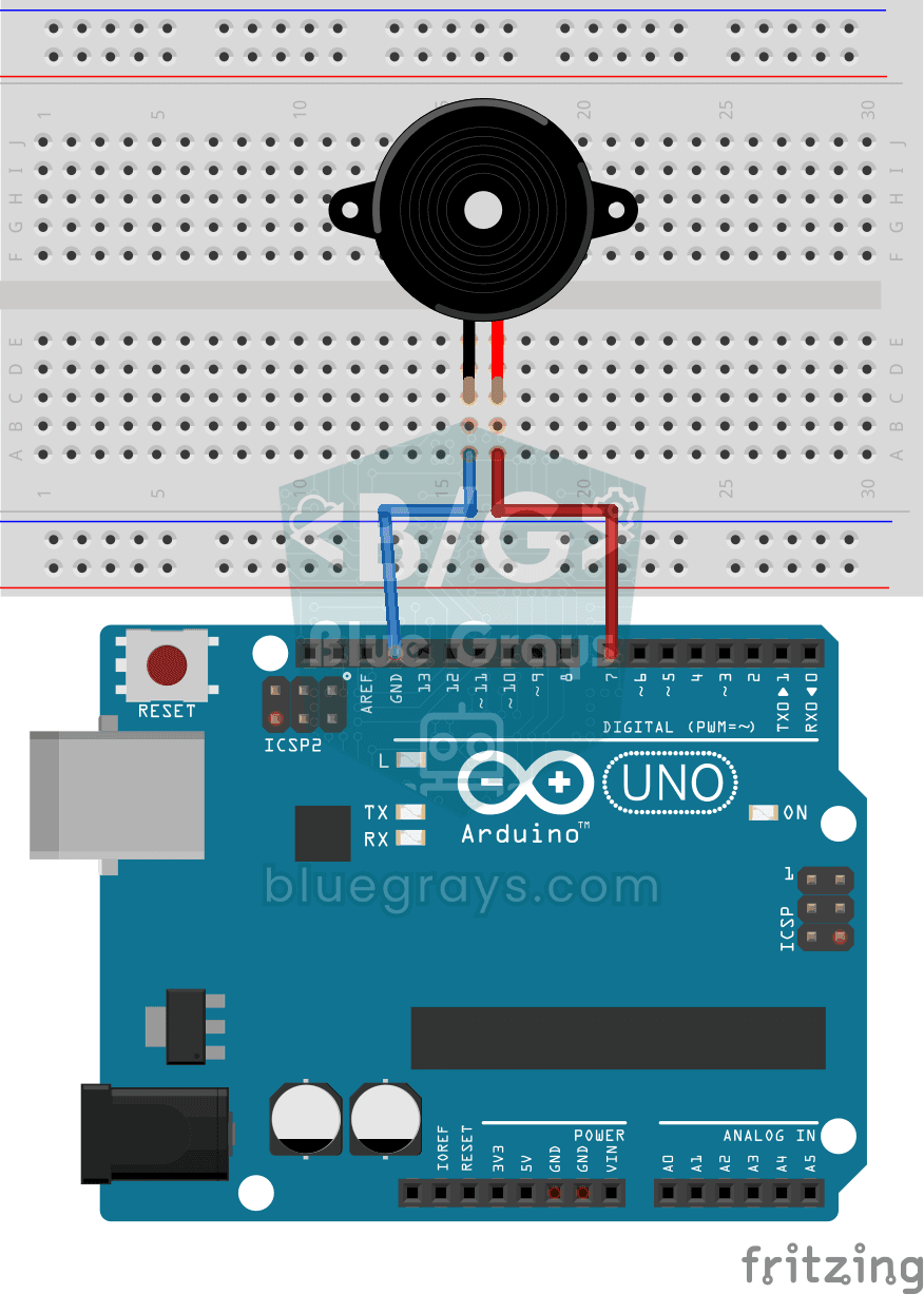
Using a Buzzer
Ever wondered how a doorbell or an alarm makes its sound? The Arduino makes a small buzzer beep at short intervals: beep, pause, beep, pause.
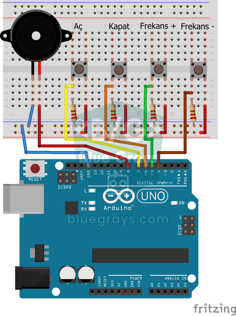
Frequency Setting with Buzzer
You control the sound of a buzzer with four buttons: one starts the sound, one silences it, and the other two make it higher or lower.
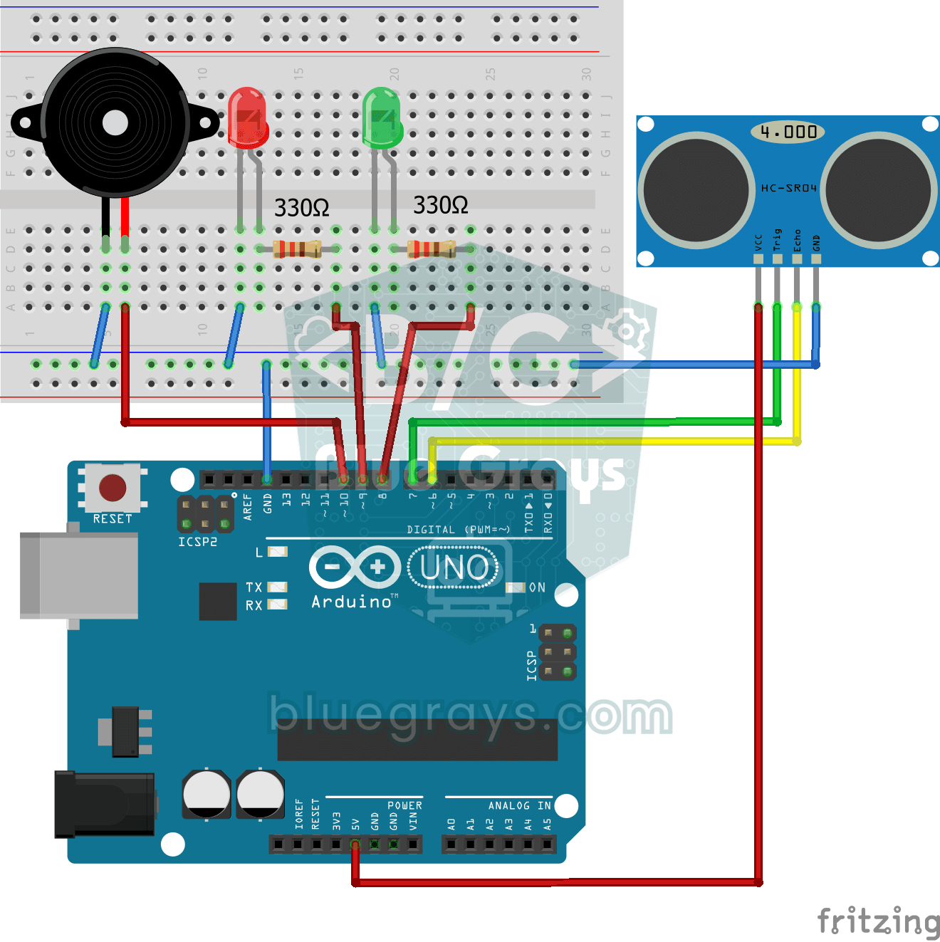
Parking Sensor with HC-SR04
A mini version of a car's parking sensor: the closer something gets, the faster the beeps.
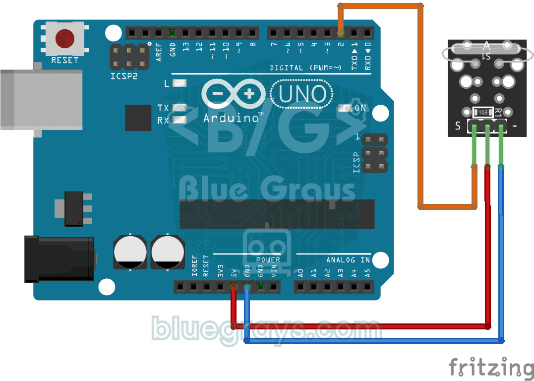
Reading a Reed Switch
Ever wondered about the magnetic switch inside door and window alarms? When a magnet comes near the reed relay module, the tiny switch inside it closes; the Arduino reads it once a second and prints…
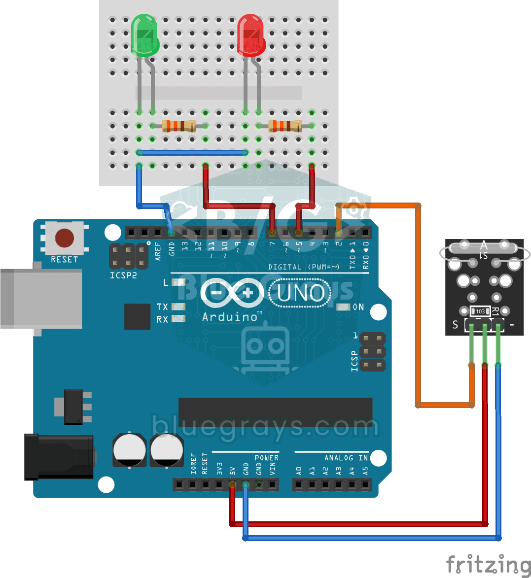
Reed Switch Door Sensor
Tell whether your door is open or closed just by looking at a light. You attach a small magnet to the door and a magnet-sensing switch to the frame; when the door is closed they sit side by side and…

ESP32 Parking Sensor (HC-SR04 + 5-LED Bar + Buzzer + OLED)
The ESP32 version of a car parking sensor! The HC-SR04 ultrasonic sensor measures the distance to the object in front. As it gets closer, a 5-LED bar fills up (green → yellow → red) and the buzzer beeps faster. Very close (under 10 cm), a continuous alarm sounds and all LEDs light up. The SSD1306 OLED display shows the live distance in cm in large text, plus a status message.

LED Blink with ESP32
Teaches basic GPIO output usage with ESP32. We achieve a blinking effect by turning an LED on and off from a digital pin. ESP32 version of the classic blink project on Arduino UNO; the basic blink commands in the Arduino environment are the same, but the ESP32's pin layout and 3.3 V GPIO levels differ from those of the Arduino UNO.